Table of Contents
Advertisement
Quick Links
Download this manual
See also:
User Manual
Advertisement
Table of Contents

Subscribe to Our Youtube Channel
Related Manuals for BK Precision DAS240-BAT


Summary of Contents for BK Precision DAS240-BAT
-
Page 2: Safety Summary
Safety Summary The following safety precautions apply to both operating and maintenance personnel and must be followed during all phases of operation, service, and repair of this instrument. Before applying power to this instrument: • Read and understand the safety and operational information in this manual. •... - Page 3 Electrical Power This instrument is intended to be powered from a CATEGORY II mains power environment. The mains power should be 115 V RMS or 230 V RMS. Use only the power cord supplied with the instrument and ensure it is appropriate for your country of use.
- Page 4 Do not operate instrument if damaged If the instrument is damaged, appears to be damaged, or if any liquid, chemical, or other material gets on or inside the instrument, remove the instrument’s power cord, remove the instrument from service, label it as not to be operated, and return the instrument to B&K Precision for repair.
-
Page 5: Safety Symbols
Do not substitute parts that are not approved by B&K Precision or modify this instrument. Return the instrument to B&K Precision for service and repair to ensure that safety and performance features are maintained. For continued safe use of the instrument •... -
Page 6: Table Of Contents
1.4.2 Example: Power-Line, engine noise, or other electrical noise. Setup Switching On 2.1.1 Switching Off 2.1.2 In Case of Error Extension Modules (DAS240-BAT only) External Power Battery 2.4.1 To Ensure Long Battery Life 2.4.2 To Charge the Battery Calibration 2.5.1... - Page 7 Recording Create a Recording View Recording 7.2.1 Loading a Recording Triggering Recordings Waiting Start Condition Recordings Triggering 8.3.1 Single Analog Channel Trigger 8.3.2 Single Threshold 8.3.3 Multiple Thresholds 8.3.4 Trigger Examples Trigger on Logic Channels Alarms Alarm Status Analog/Math/Timing Signal Alarm Analog Signal Combination Alarm Logic (Digital) Signal Alarm Trigger Alarm on Recording Start (Trigger Acquisition)
- Page 8 15 Thermocouple Measurement Accuracy 15.1 J Type Thermocouple Example 15.2 Measurement Accuracy: Pm 15.3 Voltage of Thermocouple (mV) 15.3.1 Example of Accuracy Calculation 15.4 Accuracy Class - Class Index 15.5 Grounding 16 LIMITED TWO-YEAR WARRANTY 17 Service Information...
-
Page 9: Introduction
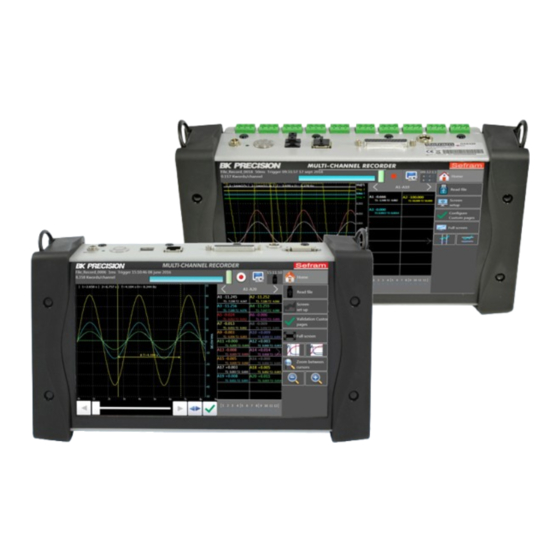
DAS240-BAT DAS220-BAT Figure 1.1 Front View The DAS240-BAT and DAS220-BAT programmable recorders can measure measure voltage, current, temperature (ther- mocouple, Pt100, Pt1000), resistances, and logic channels. Highlights include: • An intuitive interface on a wide capacitive and color 10” touchscreen •... - Page 10 Power Connector Charging LED ON/OFF Switch USB Connectors LAN Interface Logic and Alarm Signals Ground Expansion Module Figure 1.2 DAS240-BAT Electrical Connections Item Description Channel Inputs Power Connector Charging LED ON/OFF Switch USB Connectors LAN Interface Logic and Alarm Signals Ground Figure 1.3 DAS220-BAT Electrical Connections...
-
Page 11: Home Screen
Figure 1.4 Terminal Block and Cable 1.3 Home screen The home screen provides access to the various functions and settings of the unit. Access this menu via the “Home” button in the top right corner of the screen. Item Description Setup Menu Trigger Menu Logic Channel Config Menu... -
Page 12: Example: Recording 9 Channels
1.4.1 Example: Recording 9 Channels For example, if 9 channels are sampled, and the settings for each channel sample period are [50, 50, 20, 20, 20, 20, 10, 10, 5] ms each, the total time for an acquisition is 200 ms. Consequently, the minimum recording period, the time between samples of an individual channel, is 200 ms. -
Page 13: Setup
2.1 Switching On Prior to powering ON the unit, connect the extension modules (DAS240-BAT). Turn on the recorder by pressing the button at the top. When the recorder is on, the ON/OFF button will illuminate, and displays a startup screen showing the hardware version. It then switches automatically to “F(t)” mode. This display is accessible from the “Home”... -
Page 14: In Case Of Error
• Assemble the extension modules together • Screw the plates with the adjacent modules • Stick the additional adhesive buttress • Connect the cable using unlocking levers • Connect the cable on the DAS240-BAT (must be powered off first) • Switch on the unit. -
Page 15: External Power
Note: The unit is delivered with a 70 cm cable. 2.3 External Power The DAS240-BAT and DAS220-BAT recorders are powered and charged using a 15V DC, 5A power supply. Warning: To minimize the risk of shock, the instrument chassis and cabinet must be connected to an electrical safety ground. -
Page 16: To Charge The Battery
When the battery is nearly discharged, the unit closes all open files, stops the software, and will shut off automatically. 2.4.2 To Charge the Battery • Connect the provided external AC adapter to the power input of the unit. • Connect the AC adapter to a electrical outlet. •... -
Page 17: Keypad Lock
1. Let the unit warm up for 20 minutes at ambient temperature 68-77F (20-25C). 2. Enter the recorder main page and then press the “Setup” key. 3. Select the “Additional Option” menu. 4. Select the “Electric Calibration” menu. 5. Press the “Recover factory calibration”. 6. -
Page 18: Screen Shut Off (Dimming)
Figure 2.7 System Languages 2.9 Screen Shut Off (Dimming) The amount of time the screen back-light stays at full brightness may be set from 1-30 mins or (disabled). Use the arrow keys to change the screen shut off timeout. 2.10 VNC VNC (Virtual Network Computing) allows the user to mirror the front panel using a viewer on a networked computer. -
Page 19: Alarms
Figure 2.8 Network Configuration Dialog Pressing the button opens the network configuration dialog. Available options are shown in this window depending on the hardware connected. DHCP, IP Address, Subnet Mask, and Gateway IP can be configured here. 2.15 Alarms Chapter 9 for details. -
Page 20: Channel Setup
For example, the plot color and thickness can be set here. See Figure 3.2. 3.3 Extension Modules (DAS240-BAT only) Up to 10 extension modules may be connected at a time. To assemble multiple terminal block modules: •... -
Page 21: Measurement Connections
Figure 3.2 Channel Configuration Screen Figure 3.3 Extension Modules • Connect the cable using unlocking levers • Connect the cable on the DAS240-BAT (must be powered off first) • Switch on the unit. Note: The unit is delivered with a 70 cm cable. -
Page 22: Temperature Measurement With A Thermocouple
Figure 3.4 Breakout Cable and Module Figure 3.5 Terminal Blocks 3.4.2 Temperature Measurement With a Thermocouple The voltage resulting from thermocouple is measured between the + and - terminals of the relevant input. The “GND” terminal is not used. Errors in reading temperature can be caused by reverse connection of the thermocouple wires. 3.4.3 Temperature Measurement With Pt100/Pt1000 and RTD The Pt100/Pt1000 probe must be connected to the + and - terminals. -
Page 23: Current Measurement
set the on screen range close to the expected measurement value. Based on the range chosen, the unit determines the sense current and voltage range to use for measurement. 3.4.5 Current Measurement The recorder includes the option to convert sensed voltage across a shunt or sense resistor into a current reading. From the “Home”... - Page 24 Figure 3.8 Current Shunt Value Setup Figure 3.9 50Ω Shunt Module...
-
Page 25: T) Plot
F(t) Plot This mode displays the channel signals versus time, much like an oscilloscope. The time per division is called the “Timebase” on this unit. The display is normally in a scrolling mode displaying real time data. This changes when recording data. -
Page 26: Custom Pages
Figure 4.3 Screen Setup Dialog - XY mode 4.1.1 Custom Pages Using this menu, set the channels to see on screen from the available channels set using the “Channels and Functions On/Off” menu. The channels are divided into banks and the shown bank is set here. For example, this allows channels 1 and 10 to be shown on the screen and turn off... -
Page 27: Time Base
Figure 4.4 Horizontal Cursor Options Figure 4.5 Time Base Setting (Time/Division) 4.3 Time Base The trace time scale may be set to a number of values. Pressing the Timebase button on the right of the F(t) plot screen brings up the dialog as shown in Figure 4.5. -
Page 28: Math Functions
Figure 4.6 F(t) Channel Math Settings Dialog Figure 4.7 F(t) Channel Math Functions Dialog • channel number (with its color) • function name • value 4.4.1 Math Functions Math function values may be moved around on the screen. To move the math values, click and drag them to a desired position on screen. - Page 29 Figure 4.8 Math Dialog Box The most frequent value below the median High The most frequent value above the median Amplitude On positive oscillation ������−������ℎ ∗ 100 ������������������ On negative oscillation ������−������ ∗ 100 ������������������ Average frequency �� ���������� Duration of N complete periods Average duration of a complete cycle cal- Cycle average ��...
- Page 30 Falling edge T1 = 90% Amplitude T2 = 10% Amplitude Tfall = T2 - T1 Positive pulse width Measurement of the time of 1st positive pulse. It is measured at 50% of am- plitude Negative pulse width Measurement of the time of 1st negative pulse. It is measured at 50% of amplitude positive pulse duration Positive duty cycle...
-
Page 31: Xy Plot
XY Plot The XY mode is accessible via the main menu by pressing the XY key. In this mode, one of the channel represents the horizontal axis (X), and the other channel the vertical axis (Y). For example, if the channel for the horizontal axis is 1V and the channel for the vertical axis is at 95F, the recorder plots a point at (1,95). - Page 32 Figure 5.3 Numerical Window 1. The keys : selects the group to view. 2. By pressing a specific channel: − The graph terminals are bound to this channel. − In real time acquisition, the instant value will show up. − By visualizing the cursors; then the difference value between cursors as well as T1 and T2 values corresponding to cursors T1 and T2 will be displayed.
-
Page 33: Numeric Display
Numeric Display The numerical window allows to visualize in real time the values of each channel. See Figure 6.1. The number of channels shown per screen depends on the number of channels selected. Each display page is accessed by pressing the right and left arrows. -
Page 34: Recording
Recording The DAS240-BAT and DAS220-BAT can save data to internal storage. The user can then retrieve the data and review it on the unit, save it to a USB drive, or retrieve it via the Ethernet interface. 7.1 Create a Recording To create recordings, press the “record”... - Page 35 Figure 7.3 Recording started Figure 7.4 Recording playback 1. Press the button. This will open Figure 7.5. 2. Press the “Read File” button within the new dialog. 3. Navigate and select the recording to view. 4. When a file is selected, a new button appears .
- Page 36 Figure 7.5 Load Saved Recording File Dialog Figure 7.6 File Browser Figure 7.7 Saved Recording Loaded...
-
Page 37: Triggering Recordings
Triggering Recordings Item Description Record file path Recording size Reading storage rate (reading period) Start condition Stop condition Trigger arm state Figure 8.1 Trigger Menu The start and stop functions control the conditions that initiate data recording. Opening the “Start”, or “Stop” trigger menus open the start condition dialogs with the following recording start options: Manual pressing a key... -
Page 38: Triggering
Wait for a Time Wait for a Date Figure 8.2 “Waiting” Start Conditions • Start: Start condition of the data acquisition • Stop: Stop condition of the data acquisition − Automatic: when the file is full − Trigger: on a channel or a combination of analog or logic channels •... -
Page 39: Single Threshold
Figure 8.3 Start Condition Dialog 1. Select trigger, and “Analog Channel” from the trigger dialog. 2. Set the amount of Pre-trigger samples to record. 3. Choose the trigger source channel. 4. Select the trigger condition (Threshold, level (higher/lower), or edge) 5. -
Page 40: Multiple Thresholds
Pre-triggering (only for start): Gives the acquisition time before the trigger appears. 8.3.3 Multiple Thresholds After selection of a trigger on a set of logic channels, the window allows you to set the trigger under several conditions. Then, by pressing the various thresholds in front of their respective channels, you open the threshold parameter window. Figure 8.5 Multiple Threshold Trigger Screen •... -
Page 41: Trigger Examples
8.3.4 Trigger Examples • Edge trigger: you need a change of status Example: Channel A1, rising edge, threshold = 0V: triggers only if the signal status changes from negative to positive • Level trigger: no need to pass the threshold Example: Channel A1, high level, threshold = 0V: triggers only if the signal is positive •... -
Page 42: Alarms
Alarms 4 configurable alarm signals allow signaling from the recorder through the digital port. The alarm signals are high (5V) when the alarm condition is detected. The main display’s alarm status section indicates the status of the alarms. The main display alarm status is “sticky” in that when alarm triggers, the field is set to active (red). See Figure 9.3. -
Page 43: Analog/Math/Timing Signal Alarm
The status of all 4 alarms is always visible in the top ribbon, each with its own small square. The status of each alarm is indicated 3 colors: Alarm disabled Transparent Alarm enabled, not triggered Blue Alarm enabled and triggered To clear an alarm, press the on screen box containing the alarm statuses. -
Page 44: Logic (Digital) Signal Alarm Trigger
The set of signals configured will trigger the alarm if 1 threshold is true, or all thresholds are true. This is set by the AND/OR condition at the top of the dialog. Figure 9.6 Analog Combination Trigger 9.4 Logic (Digital) Signal Alarm Trigger An alarm based on the logic state of the digital input is configured by selecting the “Logical Channels”... -
Page 45: Alarm On Recording Start (Trigger Acquisition)
9.5 Alarm on Recording Start (Trigger Acquisition) An alarm is also available for signaling the start of a recording. Select the “Trigger Acquisition” option to enable this type of alarm. Figure 9.8 Trigger on Alarm... -
Page 46: Logic Channels
Logic Channels Up to 12 logic channels can be recorded simultaneously with the analog channels. In addition, 4 timing channels are also available for measuring duty cycle, RPM, and pulse count. 10.1 Logic Input Connector This is a DB-25 connector located on the top of the unit. Pin Signal Pin Signal 13 Logic Ch 1 19 Function K2... -
Page 47: Timing
Item Description Channel number, color and arrows to change channel Channel count Enable logic channels Connector (red - selected channel) Additional pin information Channel #, pin, and state (dim - disabled) Figure 10.3 Logic Channel Configuration Screen 10.3 Timing Function channels K1-4 are used for measuring the PWM duty cycle, count, or frequency of up to 4 digital signals. They are also 3.3V level signals and tolerant of 24V. - Page 48 Figure 10.5 Single Timing Function Setup Screen...
-
Page 49: File Management
File Management The recorder is capable of creating recordings, screenshots, and saving device setup configurations. All of these are stored as files, “*.rec” for recordings, “*.bmp” for screenshots, and “*.cfg” files for configurations. The file view dialog Figure 11.1 is accessible from the “Home>Setup”, “(Waveform)>Screen Setup>Background”, “Home>View Records”, “Home>Setup>Load/Save on Disk”... -
Page 50: Default
Default Sets up the appliance in standard configuration Load from disk Loads a configuration from a file in the internal flash disk or an USB stick Save to disk Saves a configuration into a file in the internal flash disk or an USB stick These commands are only available when the data recording is stopped. -
Page 51: Remote Interfaces
Remote Interfaces 12.1 LAN Interface The LAN connection to the DAS240-BAT supports ModBus, VNC, Sefram Viewer and DAS Lab. Sefram Viewer and DAS Lab are tools provided by B&K/Sefram, and are available as a single download from http://www.bkprecision .com. The LAN connection supports 10mBit and 100mBit networks. In the case where a network is not available, using a crossover cable is also possible. -
Page 52: Viewing With Seframviewer
DHCP Static Figure 12.2 LAN Setup 12.4 Viewing with SeframViewer You can transfer the data acquisition files to a PC computer for viewing. The SeframViewer software is provided on a CD-ROM with the appliance. You can use it to view the recorded files or convert it into xls or txt files. -
Page 53: Example
• Manage configurations remotly using network via Ethernet or WiFi • Download your record files using network via Ethernet or WiFi According to your needs, click on the right button. If you want manage your DAS240-BAT or DAS220-BAT using network, enter the IP address to establish the connection. -
Page 54: Modbus (Slave)
That protocol is dialog based (question-answer) : the client (master) send a command, and then the server (slave), send back wanted data. The DAS240-BAT/DAS220-BAT includes a Modbus TCP Slave service. 12.6.1 Setup Modbus Slave The Modbus protocol uses ethernet network. So you have to choose the port used for that feature, and then enable the Modbus TCP server. -
Page 55: Mapping Modbus Tcp
In the Setup page of your instrument, then Additional option, select the “Modbus TCP Server” button. You could enable or disable the server: click on the radio button < Modbus server state >. According to your preferences, you are able to change the network port dedicated to the Modbus server. To carry out that change to a successful conclusion, you must disable the Modbus server, change the port (502 by default), and then restart the Modbus server. -
Page 56: Maintenance
Maintenance Unplug the unit before any cleaning or maintenance. Periodically clean the recorder while unplugged, in the following ways: • Use water and soap to clean the front and rear surfaces. • Never use any product that contains petroleum by-products, benzene or alcohol: damage the screen printings may occur •... -
Page 57: Specifications
Specifications Note: All specifications apply to the unit after: 1. A temperature stabilization time of 15 minutes over an ambient temperature range of 23 C ± 5 ∘ ∘ 2. Short correction operation performed before making measurement. Specifications are subject to change without notice. -
Page 58: Thermocouple Measurement Accuracy
Portable 10-channel data recorder Model DAS220-BAT Specifications Note: All specifications apply to the unit after a temperature stabilization time of 30 minutes over an ambient temperature range of 23 °C ± 5 °C. Analog Channels Acquisition System Analog Input Channels 10 integrated channels Resolution 16 bit... - Page 59 Multi-channel recorder Model DAS240-BAT Specifications Analog Channels General Number of Analog Input Channels Acquisition System 20 channels standard, expandable to 200 with optional 20-channel modules Resolution 16 bit DC Voltage Acquisition System Scan, one sample per channel ± (0.5, 1, 2.5, 5, 10, 25, 50, 100) mV V >50 mV...
-
Page 60: J Type Thermocouple Example
Thermocouple Measurement Accuracy The thermocouple measurements are treated as voltage measurements. For a given range of temperature measurement, the software calculates the voltage caliber the following way: • Let < T > the absolute value of the max. measurable value, in ∘... -
Page 61: Example Of Accuracy Calculation
• At 100 C the slope of thermocouple J is 55��V ∘ • At -100 C slope is 30��V . ∘ • So the error is 2 time greater then 100 C to -100 ∘ ∘ 15.3.1 Example of Accuracy Calculation You make a welding between -50 C and +50 C with a J thermocouple with compensation of cold welding. -
Page 62: Grounding
15.5 Grounding • If the source of the signal you have to record has low internal impedance, you shall use twisted wires. In case of high impedance, you shall use shielded wires. • When gathering grounds from the various items on the measurement line, it is good to check that there is no voltage difference between them, in order to prevent any shortcut. -
Page 63: Limited Two-Year Warranty
LIMITED TWO-YEAR WARRANTY B&K Precision Corp. warrants to the original purchaser that its products and the component parts thereof, will be free from defects in workmanship and materials for a period of two years from date of purchase. B&K Precision Corp. will, without charge, repair or replace, at its option, defective product or component parts. Returned product must be accompanied by proof of the purchase date in the form of a sales receipt. -
Page 64: Service Information
Service Information Warranty Service: Please go to the support and service section on our website at bkprecision.com to obtain an RMA #. Return the product in the original packaging with proof of purchase to the address below. Clearly state on the RMA the performance problem and return any leads, probes, connectors and accessories that you are using with the device.
Need help?
Do you have a question about the DAS240-BAT and is the answer not in the manual?
Questions and answers