Table of Contents
Advertisement
Quick Links
See also:
User Manual
Version: V1.00.000
Revised date: Sep-27-2018
Statement: LAUNCH owns the complete intellectual property rights for the software
used by this product. For any reverse engineering or cracking actions against the
software, LAUNCH will block the use of this product and reserve the right to pursue
their legal liabilities.
Advertisement
Table of Contents

Related Manuals for Launch X-431 PAD III


Summary of Contents for Launch X-431 PAD III
- Page 1 Statement: LAUNCH owns the complete intellectual property rights for the software used by this product. For any reverse engineering or cracking actions against the software, LAUNCH will block the use of this product and reserve the right to pursue their legal liabilities.
- Page 2 LAUNCH is not responsible for any use of this information as applied to other units. Neither LAUNCH nor its affiliates shall be liable to the purchaser of this unit or third parties for damages, losses, costs, or expenses incurred by purchaser or...
- Page 3 In places using the tool may cause interference or generate a potential risk, please turn it off. X-431 PAD III is a sealed unit. There are no end-user serviceable parts inside. All internal repairs must be done by an authorized repair facility or qualified technician.
- Page 4 LAUNCH X-431 PAD III User Manual Do not drive the vehicle and operate the tool at the same time. Any distraction may cause an accident. Keep clothing, hair, hands, tools, test equipment, etc. away from all moving or hot engine parts.
-
Page 5: Table Of Contents
1.3 T ............... 2 ECHNICAL PECIFICATIONS 1.3.1 X-431 PAD III tablet ................2 1.3.2 VCI connector (Only for Passenger Vehicle Version) ......3 1.3.2 VCI module (Only for Commercial Vehicle/ Gasoline & Diesel Version) ........................3 2 KNOWLEDGE OF X-431 PAD III..............4 2.1 X-431 PAD III T... - Page 6 ................. 51 EMOTE IAGNOSIS 5.3.1 Interface layout................51 5.3.2 Add friends ..................52 5.3.3 Start instant messaging ..............53 5.3.4 Launch remote diagnosis (Device-To-Device) ......... 55 5.3.5 Launch remote diagnosis (Device-To-PC) ........58 5.4 H ?............60 OW TO IAGNOSTIC ISTORY 5.5 H...
- Page 7 LAUNCH X-431 PAD III User Manual 6.6 G ..................66 EARNING 6.7 IMMO S ..................67 ERVICE 6.8 I ..................67 NJECTOR ODING 6.9 B ........... 68 ATTERY AINTENANCE YSTEM ESET 6.10 D (DPF) R ....... 68 IESEL ARTICULATE ILTER EGENERATION 6.11 E...
- Page 8 LAUNCH X-431 PAD III User Manual 12 OSCILLOSCOPE (TOOLBOX)..............94 12.1 I ..................94 NTRODUCTION 12.2 S & A ..............95 TRUCTURE CCESSORIES 12.2.1 Scopebox structure ............... 95 12.2.2 Scopebox accessories ..............96 12.3 C & I ..............99 ONNECTION NITIAL 12.3.1 Probe Compensation..............
- Page 9 LAUNCH X-431 PAD III User Manual 14.8.4 About ................... 137 14.8.5 Clear Cache ................137 14.8.6 Login/Exit from current account ........... 137 15 OTHER MODULES ................... 138 15.1 E ....................138 MAIL 15.2 B .................... 138 ROWSER 15.2.1 Open browser................138 15.2.2 Download files ................
-
Page 10: Introduction
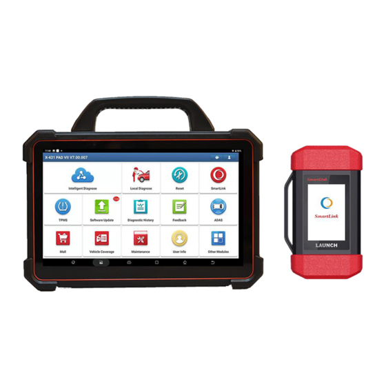
1.1 Product Profile Featuring customized Android operating system, 2.0GHz 8-core CPU and 10.1” display screen, X-431 PAD III has functions of vehicle diagnosis, oscilloscope, ignition, sensor, multimeter, browser and battery test etc. It features wired network, meanwhile it also supports Wi-Fi communication,... -
Page 11: Technical Specifications
LAUNCH X-431 PAD III User Manual owners with attentive service to develop new business opportunities, manage technicians and golo customers more efficiently, monitor customer’s vehicle running status in real-time manner and perform remote assistance anywhere etc. It is very helpful to increase productivity and boost shop revenue. -
Page 12: Vci Connector (Only For Passenger Vehicle Version)
X-431 PAD III User Manual LAUNCH Battery 15000mAh lithium-polymer battery Operating Temp. -10℃ ~ 55℃(14 ~131℉) Storage Temp. -20℃ ~ 70℃(-4 ~158℉) 1.3.2 VCI connector (Only for Passenger Vehicle Version) Working Voltage DC 9V ~ 18V ℃ ℃ ℉ Working Temp. -
Page 13: Knowledge Of X-431 Pad Iii
2 Knowledge of X-431 PAD III There are two main components to the X-431 PAD III system: X-431 PAD III Tablet – the central processor and monitor for the system (See Chapter “2.1”). Fig. 2-1 X-431 PAD III tablet ... -
Page 14: Pad Iii Tablet
X-431 PAD III User Manual LAUNCH 2.1 X-431 PAD III Tablet Fig. 2-3 X-431 PAD III tablet Adjustable Flip out it to any angle and work comfortable at kickstand your desk, or hang it on automotive part. To connect the USB devices or add-on USB... - Page 15 X-431 PAD III User Manual LAUNCH VOLUME +/- Key To adjust the volume. Reset Switch USB1 Port Only reserved for Micro USB cable. To connect an external projector or monitor with HDMI Port HDMI interface. Memory Card Slot To insert a memory card for memory extension.
-
Page 16: Vci Connector (Only For Passenger Vehicle Version)
LAUNCH X-431 PAD III User Manual 2.2 VCI Connector (Only for Passenger Vehicle Version) Fig. 1-2 VCI connector OBD-16 diagnostic To connect on vehicle’s OBD2 DLC. connector For connecting the USB cable to the tablet to Mini USB port perform vehicle diagnosis. -
Page 17: Vci Module (Only For Commercial Vehicle/Gasoline & Diesel Version)
X-431 PAD III User Manual LAUNCH 2.2 VCI Module (Only for Commercial Vehicle/Gasoline & Diesel Version) Compatible with Passenger & Commercial vehicles, the VCI module works as a vehicle communication interface device. It is used to read the vehicle data and then send it to the tablet via Bluetooth/Wi-Fi communication or USB cable connection. -
Page 18: Package List
2.3 Package List Common accessories for each X-431 PAD III are same, but for different destinations, the accessories of X-431 PAD III may vary. For detailed accessory items, please consult from the local agency or check the packing list supplied with X-431 PAD III together. - Page 19 X-431 PAD III User Manual LAUNCH BMW F chassis line Power adaptors 1 for America area and 1 for Europe area For connecting the VCI connector to the Micro-USB cable tablet to perform vehicle diagnosis. A piece of paper bearing Product S/N and...
-
Page 20: Initial Setup
LAUNCH X-431 PAD III User Manual 3 Initial Setup 3.1 Charging X-431 PAD III *Notes: • Only use the included power adaptor to recharge the tablet. Use of any other adaptor will damage the tool. We assume no responsibility for damage or loss resulting from using other similar adaptors other than the specified one. -
Page 21: Adjusting Screen Brightness
LAUNCH X-431 PAD III User Manual to visit the official website. to capture the current screen and all captured screenshots are stored in the Screenshots folder. shows whether the VCI device is connected properly or not. to display a list of applications that are currently running or recently used. -
Page 22: Network Setup
X-431 PAD III User Manual LAUNCH 3.6 Network Setup There are 2 kinds of network connection available on the tablet. 3.6.1 Wired Connection Connect the Ethernet crossover cable to the tablet, and the system will directly use the Ethernet connection as the default connection since it provides more stable and faster network speed. -
Page 23: Getting Started
LAUNCH X-431 PAD III User Manual 4 Getting Started 4.1 Diagnostic Flowchart For new users, please follow the operation chart shown in Fig. 4-1 to start using X-431 PAD III. Fig. 4-1 *Note: If “VIN Scan” or “Intelligent Diagnosis” is selected to diagnose a vehicle, this step shall not apply. - Page 24 X-431 PAD III User Manual LAUNCH Fig. 4-2 (If you are a new user, follow to proceed.) (If you have registered to be a member, go to to login the system directly.) (In case you forgot password, refer to to reset a new password.) A.
- Page 25 X-431 PAD III User Manual LAUNCH Fig. 4-4 2. Register Wallet: Input the password for the Wallet (An 8-20 mixture of lower/upper case letters, numbers and special characters is recommended), and then tap “Create a Wallet account”. *Note: You are suggested to note the password down for future use.
- Page 26 LAUNCH X-431 PAD III User Manual 3. Activate VCI: After registering a wallet account, the system navigates to the following screen: Fig. 4-6 In Fig. 4-6, input the Product Serial Number and Activation Code, which can be found in the supplied password envelope.
-
Page 27: Home Screen
“Login” button to enter the main menu screen directly. *Note: The X-431 PAD III has an auto-save function. Once the username and password are correctly entered, the system will automatically store it. After initial setup, it is no longer necessary to input the account information manually to log in. - Page 28 X-431 PAD III User Manual LAUNCH through this module. Local Diagnose To diagnose a vehicle manually. This option aims to help repair shops or technicians Remote Diagnose launch instant messaging and remote diagnosis, making the repair job getting fixed faster.
-
Page 29: Vehicle Menu Layout
Recently Tab: Displays all the recently tested vehicle makes. Regional buttons: Tap different buttons to switch to corresponding vehicles. If you have purchased an X-431 PAD III of Gasoline & Diesel Version, a Heavy-duty tab will appear next to the regional button. -
Page 30: Diagnostics Toolbar
LAUNCH X-431 PAD III User Manual Home Button: Navigates to the Home screen. Search bar: Enables you to use the virtual keyboard to quickly locate the vehicle model. Input the desired vehicle model to start searching. Vehicle model display area Locator &... -
Page 31: Diagnosis Methods (Only For Passenger Vehicle Version)
Exit the diagnostic application. 4.3 Diagnosis Methods (Only for Passenger Vehicle Version) X-431 PAD III tablet supports 2 communication methods with the VCI connector: wireless Bluetooth and USB cable. You may choose any one of the methods to diagnose a vehicle. -
Page 32: Diagnosis Methods (Only For Commercial Vehicle/ Gasoline & Diesel Version)
Bluetooth and USB cable. Choose any one of the methods to diagnose a vehicle. Fig. 4-10 *Notes: While using the diagnosis via Bluetooth, the VCI module should be paired with the X-431 PAD III tablet. If no Bluetooth setting is done before diagnostic software is... -
Page 33: Connections
USB cable. In this case, the USB cable is required to connect the VCI module and the X-431 PAD III tablet. To ensure that the X-431 PAD III tablet can work with the VCI module via Wi-Fi communication, a Wi-Fi configuration is required. Refer to Chapter 4.5.3 for details. - Page 34 3. Choose one of the two ways to obtain power from: A. Power adaptor: Connect one end of the included power adaptor to DC IN port of X-431 PAD III tablet, and the other end to AC outlet. B. Internal battery pack For non-OBDII vehicle, proceed as follows: 1.
-
Page 35: Vehicle Connection (For Commercial Vehicle/ Gasoline & Diesel Version)
X-431 PAD III User Manual LAUNCH Fig. 4-13 B. Battery Clamps Cable: Connect one end of the battery clamps cable to vehicle’s battery, and the other end to the power jack of OBD I adaptor. Fig. 4-14 4.3.3 Vehicle connection (For Commercial Vehicle/ Gasoline & Diesel Version) The method used to connect the VCI module to a vehicle’s DLC depends on the... -
Page 36: Communication Setup (Only For Passenger Vehicle Version)
LAUNCH X-431 PAD III User Manual *Notes: a). For commercial vehicles, refer to the above connection method to proceed. b). For passenger vehicles, replace the “Non-16pin connector” with “OBD I adaptor” + “non-16pin connector (for passenger vehicles)”. Other connections shall also apply. -
Page 37: Usb Cable Connection
USB connection is successful. *Note: The USB connection provides the most stable and fastest communication. When all communication methods are applied at the same time, the X-431 PAD III system will use the USB communication as the default priority. -
Page 38: Usb Cable Connection
USB connection is successful. *Note: The USB connection provides the most stable and fastest communication. When all communication methods are applied at the same time, the X-431 PAD III system will use the USB communication as the default priority. - Page 39 X-431 PAD III User Manual LAUNCH Fig. 4-16 2. Check the box “Use Wi-Fi communication mode”, the system will search for VCI module automatically. See Fig. 4-17 & Fig. 4-18. Fig. 4-17 Fig. 4-18 3. Tap the desired VCI module and a pairing request similar to Fig. 4-19 will appear: Fig.
- Page 40 X-431 PAD III User Manual LAUNCH Fig. 4-20 5. There are two Wi-Fi communication modes available for the VCI module. Work as Wi-Fi hotspot: Once enabled, the VCI module and then tablet automatically connect and form a LAN network to make communication. In this case, the tablet cannot surf the Internet.
-
Page 41: Diagnosis
X-431 PAD III User Manual LAUNCH 5 Diagnosis 5.1 Intelligent Diagnosis (AutoDetect) Through simple Bluetooth communication between the tablet and VCI device, you can easily get the VIN (Vehicle Identification Number) information of the currently identified vehicle. Once the VIN is successfully identified, the system will retrieve it from the remote server and then guide you to vehicle information page without performing the step-by-step manual menu selection. - Page 42 X-431 PAD III User Manual LAUNCH prompt message box will appear: Fig. 5-2 Check all the possible reasons of Bluetooth connection failure carefully, and then tap “Confirm”. Fig. 5-3 If the VCI connector was once used with other devices, you need to cancel the pairing of the connector first via either one of the following ways: •...
- Page 43 X-431 PAD III User Manual LAUNCH Fig. 5-4 2. After pairing is complete, the handset starts reading the vehicle VIN. A. If the VIN can be found from the remote server database, a screen similar to Fig. 5-5 displays: Fig. 5-5 •...
- Page 44 X-431 PAD III User Manual LAUNCH Fig. 5-6 • Tap “View record” to view the details of the current diagnostic report. • To perform other functions, tap “Quick access” to directly go to the function selection screen. Choose the desired one to start a new diagnostic session.
- Page 45 X-431 PAD III User Manual LAUNCH Tap “ “ to launch the VIN recognition module. Fig. 5-8 Place the VIN inside the viewfinder rectangle to scan it. The most recognizable location for this number is in the top left corner on the vehicle’s dashboard.
-
Page 46: Local Diagnosis
In Fig. 5-10, tap “VINScan”, the screen displays as follows: Fig. 5-11 A. Camera Scan: In this mode, the VCI connector should be plugged into the vehicle’s DLC first, and then a Bluetooth communication should be established between X-431 PAD III and the vehicle. - Page 47 • In case the handset failed to recognize it, tap to enter it manually. • To turn the flash on, tap Once the test vehicle is successfully identified, X-431 PAD III will jump to the function selection page directly. Fig. 5-13 Tap the desired option to perform the corresponding function.
- Page 48 X-431 PAD III User Manual LAUNCH software. B. INPUT VIN: In this mode, you need to input the VIN manually. In general, vehicle identification numbers are standardized - all contain 17 characters. VIN characters may be capital letters A through Z and numbers 1 through 0;...
- Page 49 Tap “Scan” to start searching for the VCI connector. Once it is found, tap it to start pairing. If the X-431 PAD III handset has paired with the VCI connector, it will enter Step 2 directly. Confirm: Tap it to go to next step.
-
Page 50: Health Report (Quick Test)
LAUNCH X-431 PAD III User Manual Fig. 5-17 5.2.1 Health Report (Quick Test) This function varies from vehicle to vehicle. It enables you to quickly access all the electronic control units of the vehicle and generate a detailed report about vehicle health. - Page 51 LAUNCH X-431 PAD III User Manual Once the scanning is complete, a screen similar to the following appears: Fig. 5-19 In Fig. 5-19, the tested system with fault code appears in red and the system with OK displays in black (normally).
-
Page 52: System Scan
X-431 PAD III User Manual LAUNCH On-screen Buttons: Search: Highlight a certain DTC item, and then tap it to launch the browser to search for more detailed information about the selected DTC online. Report: To save the current data in text format. -
Page 53: System Selection
LAUNCH X-431 PAD III User Manual Fig. 5-22 Tap the desired system to advance to the test function selection page. For detailed operations on test function, please refer to Chapter 5.2.3. 5.2.3 System Selection This option allows you manually select the test system and function step by step. - Page 54 X-431 PAD III User Manual LAUNCH Fig. 5-24 *Note: Different vehicle has different diagnostic menus. A. Version Information This function is used to read the version information of system mode, vehicle VIN, software and ECU. In Fig. 5-24, tap “Version Information”, the screen displays as Fig. 5-25.
- Page 55 X-431 PAD III User Manual LAUNCH Fig. 5-26 On-screen Buttons: Freeze Frame: When an emission-related fault occurs, certain vehicle conditions are recorded by the on-board computer . This information is referred to as freeze frame data. Freeze frame data includes a snapshot of critical parameter values at the time the DTC is set.
- Page 56 LAUNCH X-431 PAD III User Manual Fig. 5-27 Tap “Yes”, the system will automatically delete the currently existing trouble code. *Note: The trouble code will not disappear until the trouble was completely cleared. D. Read Data Stream This option retrieves and displays live data and parameters from the vehicle’s ECU.
- Page 57 X-431 PAD III User Manual LAUNCH Fig. 5-29 Notes: 1. If the value of the data stream item is out of the range of the standard (reference) value, the whole line will display in red. If it complies with the reference value, it displays in blue (normal mode).
- Page 58 X-431 PAD III User Manual LAUNCH Fig. 5-30 Fig. 5-31 Report: To save the current data in text format. All reports are saved under the tab “Diagnostic Report” in “My Report” from “Personal Center” menu. For details on report operations, please refer to Chapter 15.1 “My Report”.
- Page 59 This option is used to access vehicle-specific subsystem and component tests. Available test vary by vehicle manufacturer, year, and model. During the actuation test, the X-431 PAD III handset outputs commands to the ECU in order to drive the actuators, and then determines the integrity of the system or parts by reading the ECU data, or by monitoring the operation of the actuators, such as switching a injector between two operating states.
-
Page 60: Remote Diagnosis
Each time when an operation is successfully executed, “Completed” displays. 5.3 Remote Diagnosis This option aims to help repair shops or technicians launch instant messaging and remote diagnosis, making the repair job getting fixed faster. Tap “Remote Diagnosis” on the Home screen, the screen appears blank by default. -
Page 61: Add Friends
Contact tab Tap to enter the friend list. Tap to slide the switch to ON, the X-431 PAD III keeps WEB Remote online and becomes visible on the web client. In this case,... -
Page 62: Start Instant Messaging
5.3.3 Start instant messaging *Note: The I/M (Instant Messaging) function is open to all users who had Launch’s diagnostic tool equipped with this module. After adding your friends, tap the desired one’s photo to enter a screen similar to... - Page 63 X-431 PAD III User Manual LAUNCH Fig. 5-37 Tap the input field and use the on-screen keyboard to enter the text message, and then tap “Send” to send it. to send the voice message. to send the emoj. to call out more function options.
-
Page 64: Launch Remote Diagnosis (Device-To-Device)
Turn on the vehicle power supply. Throttle should be in a closed position. The X-431 PAD III should be properly connected to the vehicle’s DLC and a successful communication is required. In Fig. 5-38, tap “Remote Diagnostic”, a pull-down menu including the following options appears: Fig. - Page 65 X-431 PAD III User Manual LAUNCH created. Input your comments on this report, and then tap “Send Report” to send it to the partner. Tap “Request control remote device” Wait for partner’s confirmation Start connecting after request confirmed Start Diagnosis...
- Page 66 X-431 PAD III User Manual LAUNCH Cancel To cancel this operation.
-
Page 67: Launch Remote Diagnosis (Device-To-Pc)
X-431 PAD III User Manual LAUNCH 5.3.5 Launch remote diagnosis (Device-To-PC) Except that the remote diagnosis can be done between different Launch’s diagnostic tools that come loaded with the module, user also can ask for remote control from PC client technician. - Page 68 X-431 PAD III User Manual LAUNCH Fig. 5-41 1. Slide the switch “Allow device to be connected to the WEB client remote diagnostic device” to ON so that the partner can find and access to this device while using the PC.
-
Page 69: How To View Diagnostic History
The operations in remote diagnosis are same as those in local diagnosis. Once the session is complete, a remote diagnostic report will be automatically generated. 5.4 How to View Diagnostic History? Generally once a vehicle diagnosis is performed, X-431 PAD III will record the... -
Page 70: How To Feedback Diagnostic Logs
X-431 PAD III User Manual LAUNCH every details of diagnostic process. The History function provides direct access to the previously tested vehicles and users can resume from the last operation, without the necessity of starting from scratch. Tap “Diagnostic History” on the Home screen, all diagnostic records will be listed on the screen in date sequence. - Page 71 X-431 PAD III User Manual LAUNCH Fig. 5-45 Tap “CONFIRM” to choose the vehicle diagnostic record page. Fig. 5-46 A). Tap the desired vehicle to enter the diagnostic log selection page.
- Page 72 X-431 PAD III User Manual LAUNCH Fig. 5-47 Select the check box and tap “Submit”. A screen similar to the following will appear: Fig. 5-48 Choose the failure type and fill in the detailed failure description in the blank text box and telephone or email address.
-
Page 73: Special (Reset) Function (Only For Passenger Vehicle/Gasoline & Diesel Version)
X-431 PAD III User Manual LAUNCH 6 Special (Reset) Function (Only for Passenger Vehicle/Gasoline & Diesel Version) In addition to amazing & powerful diagnostic function, X-431 PAD III also features various service functions. The most commonly performed service functions contain: Oil Reset Service ... -
Page 74: Oil Reset Service
X-431 PAD III User Manual LAUNCH Follow the instructions on the screen to operate Select the service mode Select “Reset” (The available mode varies from vehicle to vehicle) Select the desired reset item (e.g. oil lamp reset Select the car brand etc.) -
Page 75: Steering Angle Calibration
X-431 PAD III User Manual LAUNCH 6.3 Steering Angle Calibration To reset the steering angle, first find the relative zero point position for the car to drive in straight line. Taking this position as reference, the ECU can calculate the accurate angle for left and right steering. -
Page 76: Immo Service
X-431 PAD III User Manual LAUNCH learning for the car. After tooth learning is successful, the MIL turns off. After the engine ECU, crankshaft position sensor, or crankshaft flywheel is replaced, or the DTC 'tooth not learned' is present, tooth learning must be performed. -
Page 77: Battery Maintenance System Reset
X-431 PAD III User Manual LAUNCH 6.9 Battery Maintenance System Reset This function enables you to perform a resetting operation on the monitoring unit of vehicle battery, in which the original low battery fault information will be cleared and battery matching will be done. -
Page 78: Software Update
X-431 PAD III User Manual LAUNCH 7 Software Update If you did not download the software in process of product registration or a pop-up message prompting you that some new software can be updated, you may use this option to download it or keep it synchronized with the latest version. -
Page 79: Golo Business Manager
X-431 PAD III User Manual LAUNCH 8 golo Business Manager This module is an individual business management application specially developed for repair shops. Before using it, you need to download the application and register a golo business account. On this platform, you can provide nearby car owners with attentive service to develop new business opportunities, manage technicians and golo customers more efficiently, monitor customer’s vehicle running status in real-time manner... - Page 80 LAUNCH X-431 PAD III User Manual Fig. 8-2 Fill in the required items: To upload the shop picture, tap the + logo to choose the desired photo. To locate company address, tap the GPS location icon to obtain it automatically.
-
Page 81: Sensorbox (Toolbox)
X-431 PAD III User Manual 9 Sensorbox (Toolbox) 9.1 Product Summary X-431 PAD III provides an optional function of automotive sensor simulation test. “Sensor” function is specially designed to diagnose and simulate vehicle sensor faults quickly and conveniently, including “DC voltage simulation”, “Fixed frequency simulation”, “Predefined waveform simulation”... -
Page 82: Structure & Accessories
Input voltage 1~12V 9.2 Structure & Accessories 9.2.1 Sensorbox structure Fig. 9-1 Structural diagram of Sensorbox Table 9-1 shows the ports and indicators for X-431 PAD III sensorbox Name Description Indicator (green) for receiving data from the Data receiving LED diagnostic tool. -
Page 83: Sensorbox Accessories
LAUNCH X-431 PAD III User Manual It keeps steady on (red) after the sensorbox Power LED is powered on. Connect the Sensorbox to the diagnostic tool Type-B USB port with USB cable. Connect to power supply through the power Power connector adaptor. -
Page 84: Sensor Simulation
X-431 PAD III User Manual LAUNCH through connection to AC outlet. Battery clamps cable To supply power to the Sensorbox through connection to vehicle's battery. Electronic control converting cable 1 Electronic control converting cable 2 9.3 Sensor Simulation 9.3.1 Connections 1. -
Page 85: Simulation Test
Alternatively, user can also tap edit box, then use the on-screen keyboard to input the desired value directly. After selecting or inputting the desired voltage based on the working characteristics of sensor, tap the button, then the X-431 PAD III will begin to output the simulation voltages. Please note the red... - Page 86 Tap the setting option tab, then tap “+” or “-” to adjust the output. After setting, to perform the test. 3. Predefined waveform simulation X-431 PAD III provides some common sensor waveforms which have been predefined to facilitate users to simulate sensor signals. As long as you call out the predefined waveform, then tap...
- Page 87 X-431 PAD III User Manual LAUNCH Fig. 9-4 Here, tap button, a screen similar to Fig. 9-5 will appear. Fig. 9-5 In Fig. 9-5, the left setting column stands for sensor types and the right area displays waveform. The sensor types are explained as below:...
- Page 88 X-431 PAD III User Manual LAUNCH For example, tap “ECT” – “Warm (NTC Thermistor)” in Fig. 9-5, the right screen will display the waveform of the sensor. Fig. 9-6 In Fig. 9-6, tap the waveform, then the pre-defined waveform has been set.
-
Page 89: Precautions On Checking Vehicle Sensor
X-431 PAD III User Manual LAUNCH will regard the waveform in the drawing area as a periodic one). Users should draw as large as wave in drawing zone so that the system can sample more points to reduce tolerance. In Fig. 9-2, tap “Hand-painted waveform simulation”, a screen similar to Fig. 9-8 will appear. - Page 90 X-431 PAD III User Manual LAUNCH When checking if there is a short in the line, please disconnect the CEU and the relevant sensor, then measure the resistance value of the ports between the connected port and the vehicle body. If the resistance value is more than 1MΩ, no fault occurs.
-
Page 91: Multimeter (Toolbox)
10 Multimeter (Toolbox) 10.1 Main Menu Make sure the X-431 PAD III handset and the sensorbox are properly connected (Refer to Chapter 9.3.1 Connections for details), launch X-431 PAD III application, tap “Toolbox” -> “Multimeter” to display the test menu. -
Page 92: Test Sample
X-431 PAD III User Manual LAUNCH The following operations can be done: ]: Erases the currently displayed waveform and display it starting from the left. ]: Reduces the range and zoom in the waveform. ]: Increase the range and zoom out the waveform. - Page 93 X-431 PAD III User Manual LAUNCH compliant with the standard, then the coolant temperature sensor shall be replaced. (2) Output signal voltage testing for coolant temperature sensor After installing the coolant temperature sensor, plug the wire connector of sensor, and then switch ignition ON, test the output signal voltage between the two terminals of wire connector.
-
Page 94: Batterybox (Toolbox)
LAUNCH 11 Batterybox (Toolbox) 11.1 Product Summary X-431 PAD III provides an optional function of automotive battery test, which adopts the latest state-of-the-art conductance testing technology in the world and can test vehicle’s battery status. Two testing environments (Inside the Vehicle and Outside the Vehicle) are available and applicable to battery test. -
Page 95: Test Environment
X-431 PAD III User Manual LAUNCH 11.2 Test Environment 11.2.1 Test environment Inside the vehicle test indicates that the battery connects to loading devices, such as engine, etc. After doing battery test, it can perform charging system and actuation system test, which is proceeded as a whole simultaneously. Charging system and actuation system test is not required but must not be performed before battery test. -
Page 96: Batterybox Structure & Accessories
X-431 PAD III User Manual LAUNCH 11.3 Batterybox Structure & Accessories 11.3.1 Batterybox structure Fig.11-1 Batterybox Below describes the ports and indicators for the Batterybox. Name Descriptions It keeps solid red after the Scopebox is powered Power LED Connect to the diagnostic tool via USB cable so B-shaped USB that the signal can be displayed on the tool. -
Page 97: Connections & Operations
X-431 PAD III User Manual LAUNCH Fig. 11-3 A/B cable 11.4. Connections & Operations 11.4.1 Connection Connect one end of the USB cable to the B-shaped USB port of the Batterybox, and tighten the captive screws, and then connect the other end to the USB port of the diagnostic tool. - Page 98 X-431 PAD III User Manual LAUNCH *Note: The sequences of inside the vehicle and outside the vehicle test are almost the same, but under inside the vehicle condition, all loads in vehicles must be powered off for getting an exact test value.
- Page 99 X-431 PAD III User Manual LAUNCH Fig. 11-6 If JIS is selected, tap , the system will enter Select testing capacity screen. Users can select corresponding standard capacity value according to battery model marked on battery. 7. Tap and the testing result will appear on the screen.
-
Page 100: Outside The Vehicle Test
X-431 PAD III User Manual LAUNCH the data, the system will judge whether battery’s charging and actuation status is normal or not. in Fig. 11-7, a dialog box will pop up as Fig. 11-8. Fig. 11-8 After detecting engine starting, follow the instructions on the screen to increase the speed. - Page 101 X-431 PAD III User Manual LAUNCH The operating time required for charging system and actuation system test varies from person to person. If the engine does not start or accelerate within 30 seconds, the system will prompt you “receiving timeout” and return to the initial status.
- Page 102 X-431 PAD III User Manual LAUNCH pole. The gear and main body of clip should be fully matched with battery poles. *Notes: 1. Battery poles inside the vehicle are enveloped by connectors, which may produce some errors for test results. The tolerance results from the resistance of connectors.
-
Page 103: Oscilloscope (Toolbox)
LAUNCH 12 Oscilloscope (Toolbox) 12.1 Introduction The Scopebox is an optional add-on module of X-431 PAD III, including automotive oscilloscope and automotive ignition waveform. Automotive oscilloscope can make the auto repair technician quickly judge the faults on automotive electronic equipment and wiring, and the oscilloscope sweep speed is far greater than the signal frequency of such vehicles, usually 5-10 times of the measured signal. -
Page 104: Structure & Accessories
X-431 PAD III User Manual LAUNCH 12.2 Structure & Accessories 12.2.1 Scopebox structure Fig 12-1 Scopebox Structure Diagram Table 12-1 shows the ports and indicators for the Scopebox. Name Description Generate a square signal with fixed 1K Fixed signal generator frequency. -
Page 105: Scopebox Accessories
X-431 PAD III User Manual LAUNCH adaptor or battery clamps cable. Communication It blinks in process of data communication. indicator It remains steady green after the Scopebox Running indicator is running. It keeps steady red after the Scopebox is Power indicator powered on. - Page 106 X-431 PAD III User Manual LAUNCH connected to the BNC to 4mm Test Lead. With these 6-way leads, you will be able to test most of the sensors and actuators on all makes and models of vehicle, including MAP, temperature, throttle position and airflow sensors, fuel pumps, primary ignition circuits and fuel injectors.
- Page 107 X-431 PAD III User Manual LAUNCH This ignition pick-up is applied in the following situations: Secondary-distributor ignition analysis, Secondary-simultaneous ignition analysis Secondary-direct ignition analysis. It has three ends: BNC connector (for connecting to Secondary CH1/CH2/CH3/CH4), crocodile clip (for Grounding) ignition pick-up...
-
Page 108: Connection & Initial Use
Channel of the Scopebox. 2. Follow Steps 1-2 in Item 2 "Connection" mentioned below to connect the Scopebox and diagnostic tool. Launch the App and open "Scope" to run it. 3. From the "Vertical Setting" menu, select the corresponding channel and set the Probe attenuation to 1:10. - Page 109 X-431 PAD III User Manual LAUNCH reference lead to the ground connector. When using the probe hook-tip, insert the tip onto the probe compensator firmly to ensure a proper connection. Fig 12-2 5. Tap the button located on the bottom of the screen, a square wave (approximately 1kHzm 2V peak-to-peak) will be displayed within several seconds.
-
Page 110: Connection
X-431 PAD III User Manual LAUNCH 12.3.2 Connection For different applications, the connection methods may vary. 1. Power the Scopebox on: Power is provided to the Scopebox in either of the following ways: • Power adaptor: Insert one end of the power adaptor into the Power interface of the Scopebox, and the other end to the AC outlet. - Page 111 X-431 PAD III User Manual LAUNCH the vehicle sensor. B. While testing Secondary-distributor ignition analysis/Secondary-simultaneous ignition analysis, 3. Connect the BNC connector of the secondary ignition pick-up to any channel of the Scopebox, and clamp the crocodile clips and high-voltage clips onto the vehicle ground and high-voltage line respectively.
-
Page 112: Initial Interface Introduction
X-431 PAD III User Manual LAUNCH clip to high-voltage line, and crocodile clips to ground. The connection is as follows: Fig. 12-5 For detailed operations, please refer to Chapter 13. 12.3.3 Initial interface introduction Fig. 12-6 displays the initial interface of the Scopebox. - Page 113 X-431 PAD III User Manual LAUNCH Fig. 12-6 Descriptions Displays the CH1/CH2/CH3/CH4 information: Readouts show the coupling and vertical scale factors of the channels. A “B” icon indicates that the channel is bandwidth limited. Working mode Horizontal trigger position marker...
-
Page 114: Operations
X-431 PAD III User Manual LAUNCH Vertical Settings Panel: Controls the amplitude of the displayed signal. User can change the volt/div, coupling and probe attenuation of the CH1/CH2/CH3/CH4. Trigger Settings Panel: Controls the start event of the sweep. Channel Selection Button Function Menu [Auto]: It indicates auto trigger setting. - Page 115 X-431 PAD III User Manual LAUNCH Fig. 12-7 <2> Channel attributes & trigger setting Channel attributes can be set via horizontal settings and vertical settings. Horizontal Settings User can make some settings directly by tapping < or > next to options.
- Page 116 X-431 PAD III User Manual LAUNCH waveform. When a trigger is set up properly, it can convert unstable displays or blank screens into meaningful waveforms. When the Scopebox starts to acquire a waveform, it collects enough data so that it can draw the waveform to the left of the trigger point. The Scopebox continues to acquire data while waiting for the trigger condition to occur.
- Page 117 X-431 PAD III User Manual LAUNCH ON: Limits the channel bandwidth to 20MHz to reduce display noise. BW Limit OFF: Get full bandwidth. ON: Turn on the invert function. Invert OFF: Restore to the original display of the waveform. Trigger setting...
- Page 118 X-431 PAD III User Manual LAUNCH Normal: This mode allows the Scopebox to acquire a waveform only when it is triggered. If no trigger occurs, the Scopebox keeps waiting, and the previous waveform, if any, will remain on the display.
-
Page 119: Auto
X-431 PAD III User Manual LAUNCH Source Select which channel as trigger signal. Condition To select pulse condition. Pulse Width Set required pulse width. High Freq Reject high frequency signals when selected. Rejection 12.4.2 Auto The Scopebox has an Auto feature that sets up the Scopebox automatically to display the input signal in a best fit. -
Page 120: Measure
LAUNCH X-431 PAD III User Manual will be temporarily invalid during calibrating. Tap [Stop] to stop calibrating. Once it becomes active, it indicates calibration has completed. *Note: In process of calibration, make sure CH1/CH2/CH3/CH4 has no signal input. Moreover, calibration may take several minutes and please be patient to wait. - Page 121 LAUNCH X-431 PAD III User Manual Fig. 12-14 <2> Horizontal / Vertical measure Horizontal Measure / Vertical Measure are used to measure voltage parameter and time parameter respectively. Drag A line upwards or downwards to control voltage. Move A line left or right to fine-tune timebase. A line is a solid line and B line is a dotted line.
-
Page 122: File Management
X-431 PAD III User Manual LAUNCH 12.4.5 File management <1> Save snapshot While viewing sampling data, tap and then [Save Snapshot] to store the current screen. <2> Snapshot manager While viewing sampling data, tap and then [Snapshot Manager] to enter. -
Page 123: Expert Reference
LAUNCH X-431 PAD III User Manual Fig. 12-17 Select the file first, and then tap to open the waveform file. Tap starting the playback and tap to stop it. Fig. 12-18 To delete the waveform file, tap to return to the previous screen. - Page 124 X-431 PAD III User Manual LAUNCH Fig. 12-19 and then [Expert Reference] to enter, the following operation can be done: : To load and recall the selected file. : To delete the selected file. : To edit the selected file.
-
Page 125: Automotive Ignition Waveform (Toolbox)
X-431 PAD III can test and analyze the secondary signal for various engine ignition systems. 13.1 Secondary-distributor ignition analysis The following connection should be made before performing it: 1. - Page 126 LAUNCH X-431 PAD III User Manual 2. Connect the B-shaped terminal of the USB cable to the Scopebox USB port, and the other end to the USB port of the diagnostic tool. 3. Plug the BNC end of secondary ignition pickup into CH1/CH2/CH3/CH4 channel of the Scopebox, and connect the high-voltage clip to high-voltage line, and crocodile clips to ground.
- Page 127 X-431 PAD III User Manual LAUNCH Fig. 13-1 1) Contact break point: the primary circuit of ignition coil cut off, the secondary voltage was sensed and increased sharply. 2) Ignition voltage: secondary coil voltage overcome the damper of high voltage...
-
Page 128: Secondary-Simultaneous Ignition Analysis
X-431 PAD III User Manual LAUNCH Seen from the waveform, the amplitudes of breaker contact closed angle, break angle and breakdown voltage and spark voltage are very clear, besides, the spark delay period and two oscillations can also be tested. For the ignition... - Page 129 X-431 PAD III User Manual LAUNCH Fig. 13-2 Fig. 13-3 below shows the valid and invalid ignition waveforms. Under the working status of valid ignition, the breakdown voltage and spark voltage are higher because the cylinder is filled with fresh combustible mixture gas, which has a lower ionization level and vice versa.
-
Page 130: Secondary-Direct Ignition Analysis
LAUNCH X-431 PAD III User Manual 13.3 Secondary-direct ignition analysis Connection: 1. Power the Scopebox on: Power is provided to the Scopebox in either of the following ways: • Power adaptor: Insert one end of the power adaptor into the Power interface of the Scopebox, and the other end to the AC outlet. - Page 131 LAUNCH X-431 PAD III User Manual Fig. 13-4 Fig. 13-5 shows the normal secondary (the upper one) and (the lower one) primary ignition waveform of direct ignition system. Beause the on/off of primary circuit is not opening/closing of mechanical contact, but the conduction of transistor.
-
Page 132: Waveform Analysis Mode
X-431 PAD III User Manual LAUNCH Fig. 13-5 13.4 Waveform analysis mode The ignition secondary single-cylinder waveform test is mainly used to: a. Analyze the ignition dwell angle of single cylinder.(ignition coil charging time) b. Analyze the capability of ignition coil and secondary high tension circuit (from ignition line to ignition voltage line). - Page 133 LAUNCH X-431 PAD III User Manual poor ignition, etc. Confirm the consistence of judgment standard (the amplitude, frequency, shape and pulse width, etc., for each cylinder), check the fault of the waveform for corresponding components. Waveform results: observe the ignition coil at the beginning of charging, the relative consistent falling edge represents the dwell angle and ignition timing of each cylinder are precise.
- Page 134 X-431 PAD III User Manual LAUNCH The waveform shown on Fig. 13-6, appears a lot of clutter on the contact break point, which is obviously caused by the serious erosion on contact break point. It can be verified via burnishing the contact or changing the circuit breaker.
- Page 135 X-431 PAD III User Manual LAUNCH Fig. 13-9 A lot of clutter will be displayed on the horizontal section of primary waveform if contact has poor grounding, as shown below figure 13-10. Fig.13-10 Fig. 13-11 shows the fault of low-voltage waveform in electronic ignition system.
- Page 136 LAUNCH X-431 PAD III User Manual failures, Fig. 13-12 just shows the major possible factors for the failures.
- Page 137 X-431 PAD III User Manual LAUNCH Fig 13-12...
-
Page 138: Personal Center
X-431 PAD III User Manual LAUNCH 14 Personal Center This function allows users to manage personal information and VCI connector. 14.1 My Report This option is used to view, delete or share the saved reports. Tap “My Report”, there are total 3 options available. - Page 139 X-431 PAD III User Manual LAUNCH Fig. 14-2 Tap the desired one to enter: Fig. 14-3 Select the desired data stream items and tap “Confirm” to jump to the playback...
-
Page 140: Vci
Once you choose the connector that belongs to other account, you have to log out, and then input the right account to continue. 14.3 VCI Management (For Passenger Vehicle Version) This option is used for X-431 PAD III to deactivate pairing up with the VCI connector via Bluetooth. -
Page 141: Vci Management (Only For Commercial / Gasoline & Diesel Version)
* Note: please be sure to keep the VCI powered on while performing the operation. 14.3 VCI Management (Only for Commercial / Gasoline & Diesel Version) This option is used to set the communication method between the X-431 PAD III and the VCI module. Fig. 14-5 * Note: For detailed operations, please refer to Chapter 4.5.3. -
Page 142: Firmware Fix
X-431 PAD III User Manual LAUNCH Fig. 14-6 Input the Serial Number and Activation Code, and then tap “Activate” to activate For details on how to obtain Activation Code, tap the link below to get help. 14.5 Firmware Fix Use this item to upgrade and fix diagnostic firmware. During fixing, please do not cut power or switch to other interfaces. -
Page 143: Change Password
X-431 PAD III User Manual LAUNCH Fig. 14-7 • Tap the user image to change it. • Tap > next to “Free Upgrade Period” to check the due date of all diagnostic software. 14.7 Change Password This item allows you to modify your login password. -
Page 144: Printer Set
X-431 PAD III User Manual LAUNCH Once you saved the print information, it will be entered automatically in the “Add Information” box every time you save the diagnostic report. 14.8.3 Printer Set This option is designed to establish a wireless connection between X-431 PAD III and the Wi-Fi printer (sold separately) while performing printing operations. - Page 145 X-431 PAD III User Manual LAUNCH Fig. 15-3 Step 1: Connect the printer: Tap “Scan” to start scanning and select the desired printer hotspot named with X-431PRINTER-XXXX (XXXX stands for 4 characters), and then tap “Connect” to enter Step 2.
-
Page 146: About
X-431 PAD III User Manual LAUNCH 14.8.4 About The software version information and disclaimer are included. 14.8.5 Clear Cache This item is used to clear the App cache. Tap “Clear Cache”, a pop-up window will appear on the screen. Tap “OK” to clear cache and the system will restart the App. -
Page 147: Other Modules
15.2 Browser 15.2.1 Open browser On the Home screen, tap Browser to launch the browser. You can choose the desired homepage or input the website address to browse. Fig. 15-1 Return to the previous page. -
Page 148: Download Files
X-431 PAD III User Manual LAUNCH Create a new tab. Input a web address. Add the current page as bookmark. Open search bar. Open bookmark list. View more options. 15.2.2 Download files Files, pictures, and applications can be downloaded from the website in browser. -
Page 149: System Ota Upgrade
X-431 PAD III User Manual LAUNCH Fig. 15-2 2. Your partner must install the TeamViewer full version program (if not installed, go to http://www.teamviewer.com to download it), and then start the software on his/her computer at the same time, in order to provide support and take control of your tablet remotely. -
Page 150: Facebook
LAUNCH X-431 PAD III User Manual on-screen instructions to download and install the update file. 3. Be patient to wait until the update is done. 15.5 Facebook Facebook is an American online social media and social networking service application. After registering, users can •... -
Page 151: Checking Wallet Tokens
LAUNCH X-431 PAD III User Manual Fig. 15-3 2. Tap “Generate the recommended QR code”, and then inform the car owner to scan it to register. Fig. 15-4 Approach 3: Optimize the diagnostic reports Tap “Reward for optimized report” in “User Info”, and then tap “Optimize report”... -
Page 152: How To Backup Wallet Tokens
X-431 PAD III User Manual LAUNCH Go to “Personal Center” -> “CDB Token” to check the total token. Fig. 15-5 Tap “Token details” to view how & when to get it. Approach 2: Tap “Start the CDB Wallet App” to navigate to the main menu screen of the Wallet App to check the tokens. - Page 153 LAUNCH X-431 PAD III User Manual Fig. 15-6 2. Tap “Manage Wallets”. Fig. 15-7 3. Tap “Export Keystore”.
-
Page 154: Es File Explorer
X-431 PAD III User Manual LAUNCH Fig. 15-8 4. Input the password. 5. Tap “Copy Keystore” and follow the prompts to select any one of the methods to save the keystore. 15.7 ES File Explorer ES File Explorer is a file and application manager. You can access and create folders on the tablet without needing to connect it to a computer. - Page 155 X-431 PAD III User Manual LAUNCH 1. Use the USB cable to connect the tablet and a computer. 2. Swipe the screen from the top, tap “USB connected”. 3. Tap “TURN ON USB STORAGE”. Now you can copy files between the tablet and the computer.
-
Page 156: Faq
LAUNCH X-431 PAD III User Manual 16 FAQ 1. How to save power? Please turn off the screen while the tablet keeps idle. Set a shorter standby time. Decrease the brightness of the screen. If WLAN connection is not required, please turn it off. - Page 157 X-431 PAD III User Manual LAUNCH 4. Tap “Clear all data” to start resetting until the tool automatically reboots. 5. How to Activate new VCI device? Note: Before registration, please make sure the network is properly connected. A. If this is the first time using the handset, please refer to “Chapter 4.2.1” in the user manual for product registration.
- Page 158 X-431 PAD III User Manual LAUNCH if necessary. Once the pairing is properly done, the system will display it as a paired device. 8. How to set up a network connection? There are 2 kinds of network connection available on the tablet.
- Page 159 X-431 PAD III User Manual LAUNCH 3. Input product S/N and follow the on-screen prompts to retrieve the password.
- Page 160 The exclusive remedy for any automotive meter found to be defective is repair or replacement, and LAUNCH shall not be liable for any consequential or incidental damages.
- Page 161 Launch website: http://www. cnlaunch.com http://www.x431.com Statement: LAUNCH reserves the rights to make any change to product designs and specifications without notice. The actual object may differ a little from the descriptions in the manual in physical appearance, color and configuration. We...
Need help?
Do you have a question about the X-431 PAD III and is the answer not in the manual?
Questions and answers