Table of Contents
Advertisement
Advertisement
Table of Contents

Related Manuals for Launch CReader 3001


Summary of Contents for Launch CReader 3001
- Page 1 V1.00.000 2017-08-28...
- Page 2 Copyright Information Copyright © 2019 by LAUNCH TECH CO., LTD. All rights reserved. No part of this publication may be reproduced, stored in a retrieval system, or transmitted in any form or by any means, electronic, mechanical, photocopying and recording or otherwise, without the prior written permission of LAUNCH.
- Page 3 The right is reserved to make change at any time without notice. Neither LAUNCH nor its affiliates shall be liable to the purchaser of this unit or third parties for damages, losses, costs or expenses incurred by purchaser or...
- Page 4 User’s Manual LAUNCH 3001 Keep the test equipment dry, clean, free from oil/water or grease. Use a mild detergent on a clean cloth to clean the outside of the test equipment, when necessary.
-
Page 5: Table Of Contents
2.6.2 Non-Continuous Monitors ............10 2.6.3 OBD 2 Reference Table ............16 2.7 DTCs and MIL Status ................18 3. Product Descriptions ..................20 3.1 Outline of CReader 3001 ..............20 3.2 Specifications ..................21 3.3 Accessories ..................21 4. Connection ..................... 22 4.1 Preparation &... -
Page 6: Introduction
OBD II test for a complete diagnosis. Featuring the 1.77” color LCD, it enables users to read/clear DTCs, record and save data. The CReader 3001 is also very easy to use. With built-in help menus and code definitions, diagnosing and repairing that dreaded Check Engine Light is now easier than ever! Moreover, CReader 3001 also features the following bi-directional “special tests”:... - Page 7 User’s Manual LAUNCH 3001 *Note: Some 1994 and 1995 vehicles have 16-pin connectors but are not OBD2 compliant. Only those vehicles with a Vehicle Emissions Control Label stating “OBD 1I Certified” are OBD2 compliant.
-
Page 8: General Information
User’s Manual 3001 LAUNCH 2. General Information 2.1 On-Board Diagnostics (OBD) I *Note: With the exception of some 1994 and 1995 vehicles, most vehicles from 1982 to 1995 are equipped with some type of first generation On-Board Diagnostics. Beginning in 1988, California’s Air Resources Board (CARB), and later the Environmental Protection Agency (EPA) required vehicle manufacturers to include a self-diagnostic program in their on-board computers. - Page 9 User’s Manual LAUNCH 3001 components were not setting codes. Some emissions problems related to degraded components only occur when the vehicle is being driven under a load. The emission checks being conducted at the time were not performed under simulated driving conditions. As a result, a significant number of vehicles with degraded components were passing Emissions Tests.
-
Page 10: Diagnostic Trouble Codes (Dtcs)
User’s Manual 3001 LAUNCH 2.3 Diagnostic Trouble Codes (DTCs) OBD 2 Diagnostic Trouble Codes are codes that are stored by the on-board computer diagnostic system in response to a problem found in the vehicle. These codes identify a particular problem area and are intended to provide you with a guide as to where a fault might be occurring within a vehicle. -
Page 11: Location Of The Data Link Connector (Dlc)
User’s Manual 3001 LAUNCH Figure 2-1 2.4 Location of the Data Link Connector (DLC) The DLC (Data Link Connector or Diagnostic Link Connector) is typically a 16-pin connector where diagnostic code readers interface with the vehicle’s on-board computer. The DLC is usually located 12 inches from the center of the instrument panel (dash), under or around the driver’s side for most vehicles. -
Page 12: Obd 2 Terminology
User’s Manual LAUNCH 3001 For some Asian and European vehicles, the DLC is located behind the ashtray and the ashtray must be removed to access the connector. If the DLC cannot be found, refer to the vehicle’s service manual for the location. -
Page 13: Obd Ii Monitors
User’s Manual 3001 LAUNCH complete its diagnostic testing are met. The “Trip Drive Cycle” for a particular Monitor begins when the ignition key is turned “On.” It is successfully completed when all the “Enabling Criteria” for the Monitor to run and complete its diagnostic testing are met by the time the ignition key is turned “Off.”... -
Page 14: Continuous Monitors
User’s Manual 3001 LAUNCH limits. Currently, fifteen Monitors are supported by OBD2 systems. Additional monitors may be added as a result of Government regulations as the OBD2 system grows and matures. Not all vehicles support all fifteen Monitors. Additionally, some Monitors are supported by “spark ignition”... -
Page 15: Non-Continuous Monitors
User’s Manual 3001 LAUNCH 2. Fuel System Monitor This Monitor uses a Fuel System Correction program, called Fuel Trim, inside the on-board computer. Fuel Trim is a set of positive and negative values that represent adding or subtracting fuel from the engine. This program is used to correct for a lean (too much air/not enough fuel) or rich (too much fuel/not enough air) air-fuel mixture. - Page 16 User’s Manual LAUNCH 3001 generates a varying voltage of up to one volt, based on how much oxygen is in the exhaust gas, and sends the signal to the computer. The computer uses this signal to make corrections to the air/fuel mixture. If the exhaust gas has a large amount of oxygen (a lean air/fuel mixture), the oxygen sensor generates a “low”...
- Page 17 User’s Manual LAUNCH 3001 more quickly, to bring the vehicle into closed-loop operation as soon as possible. The Oxygen Sensor Heater Monitor is supported by “spark ignition” vehicles only. The Oxygen Sensor Heater Monitor is a “Two-Trip” Monitor. If a fault is found on the first trip, the computer temporarily saves the fault in its memory as a Pending Code.
- Page 18 User’s Manual 3001 LAUNCH 5. EGR (Exhaust Gas Recirculation) System Monitor The Exhaust Gas Recirculation (EGR) system helps reduce the formation of Oxides of Nitrogen during combustion. Temperatures above 2500°F cause nitrogen and oxygen to combine and form Oxides of Nitrogen in the combustion chamber.
- Page 19 User’s Manual LAUNCH 3001 7. Secondary Air System Monitor When a cold engine is first started, it runs in open-loop mode. During open-loop operation, the engine usually runs rich. A vehicle running rich wastes fuel and creates increased emissions, such as carbon monoxide and some hydrocarbons.
- Page 20 User’s Manual 3001 LAUNCH 9. NOx Adsorber Monitor NOx aftertreatment is based on a catalytic converter support that has been coated with a special washcoat containing zeolites. NOx Aftertreatment is designed to reduce oxides of nitrogen emitted in the exhaust stream. The zeolite acts as a molecular “sponge”...
-
Page 21: Obd 2 Reference Table
User’s Manual 3001 LAUNCH and saves the code in its long-term memory. 12. PM Filter Monitor The particulate matter (PM) filter removes particulate matter from the exhaust stream by filtration. The filter has a honeycomb structure similar to a catalyst substrate, but with the channels blocked at alternate ends. - Page 22 User’s Manual LAUNCH 3001 Name of Monitor Continuous Misfire Monitor 3 - similar Continuous (Type 1 and 3) conditions Misfire Monitor 3 - similar Continuous (Type 2) conditions Fuel System 1 or 3 - similar Continuous Monitor conditions Catalytic Once per trip...
-
Page 23: Dtcs And Mil Status
User’s Manual 3001 LAUNCH Exhaust Gas Once per trip 3 trips Sensor Monitor PM Filter Monitor Once per trip 3 trips 2.7 DTCs and MIL Status When the vehicle’s on-board computer detects a failure in an emissions-related component or system, the computer’s internal diagnostic program assigns a diagnostic trouble code (DTC) that points to the system (and subsystem) where the fault was found. - Page 24 User’s Manual 3001 LAUNCH The computer sets a Pending DTC, but the MIL is not ordered “On.” “Freeze Frame” data may or may not be saved at this time depending on manufacturer. The Pending DTC is saved in the computer’s memory for later retrieval.
-
Page 25: Product Descriptions
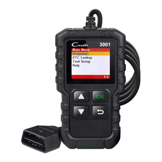
User’s Manual 3001 LAUNCH 3. Product Descriptions 3.1 Outline of CReader 3001 No. Name Descriptions OBD-16 To connect to the vehicle's DLC (Data Link Connector). connector OK key To confirm the current operation. Back to the previous page. USB port To connect to PC for system update via USB cable. -
Page 26: Specifications
” color LCD 1.77 Input voltage range: 9~18V Working temperature: 0 to 50°C Storage temperature: -20 to 70°C External Dimension: 118*68*22.3 mm Weight: <200g 3.3 Accessories 1. CReader 3001 handset 2. Quick Start Guide 3. USB cable... -
Page 27: Connection
User’s Manual LAUNCH 3001 4. Connection 4.1 Preparation & Connection 1. Turn the ignition off. 2. Locate vehicle’s DLC socket: Refer to Chapter 2.2 for the location. 3. Plug the other end of the diagnostic cable into the vehicle’s DLC. -
Page 28: Settings
User’s Manual 3001 LAUNCH *CAUTION: Don’t connect or disconnect any test equipment with ignition on or engine running. 4.2 Settings Select [Tool Setup] in the Main menu and press [OK], the system will enter the tool setup screen. 1) Language This option enables you to set the user interface language. -
Page 29: Diagnose
User’s Manual LAUNCH 3001 5. Diagnose After the tool is properly connected to the vehicle’s DLC, select [Diagnose] in Main Menu and press [OK]. The tool will automatically start a check of the vehicle’s computer to determine which type of communication protocol it is using. When the tool identifies the computer’s communication protocol, a communication link is... - Page 30 User’s Manual 3001 LAUNCH *Notes: Before performing this function, make sure to retrieve and record the trouble codes. After clearing, you should retrieve trouble codes once more or turn ignition on and retrieve codes again. If there are still some trouble codes in the system, please troubleshoot the code using a factory diagnosis guide, then clear the code and recheck.
- Page 31 User’s Manual 3001 LAUNCH operating conditions are within predefined limits. Results of these tests are stored in the on-board computer’s memory. The O2 Sensor Test function lets you retrieve and view O2 sensor monitor test results for the most recently completed tests from your vehicle’s on-board computer.
-
Page 32: Dtc Lookup
User’s Manual LAUNCH 3001 6. DTC Lookup This menu enables you to view the detailed definition of the retrieved DTC. Select [DTC Lookup] in the Main Menu and press [OK], the screen will display the interface as shown below: Press [ ] to alter the value. Press [ ] to switch to different position. After you input the DTC, press [OK] to view its detailed definition of the DTC. -
Page 33: Help
User’s Manual 3001 LAUNCH 7. Help This menu enables you to view the tool information and the OBD introduction. Select [Help] in the Main menu and then press [OK] to enter the submenu screen. It includes the following options: About OBD: Relevant introduction information about OBD. -
Page 34: Register & Update
After installation, connect one end of the USB cable to the USB port of PC, and the other end to the tool. Once the tool is powered up, launch the update tool on your computer, the system starts reading the tool. Once it obtains the tool information, it will directly navigate to the update center. -
Page 35: Faq
User’s Manual 3001 LAUNCH 9. FAQ Here we list some frequently asked questions and answers related to this tool. Question: System halts when reading data stream. What is the reason? Answer: It may be caused by a slackened connector. Please turn off the tool, firmly connect the connector, and switch it on again. - Page 36 The exclusive remedy for any automotive meter found to be defective is repair or replacement, and LAUNCH shall not be liable for any consequential or incidental damages.
- Page 37 User’s Manual 3001 LAUNCH Statement: LAUNCH reserves the rights to make any change to product designs and specifications without notice. The actual object may differ a little from the descriptions in the manual in physical appearance, color and configuration. We have tried our best to make the descriptions and illustrations in the manual as accurate as possible, and defects are inevitable.
Need help?
Do you have a question about the CReader 3001 and is the answer not in the manual?
Questions and answers
Could you please tell me what the abbreviation is stso2 ft 1 and lgso2 ft1 stand for on code reading