Table of Contents
Advertisement
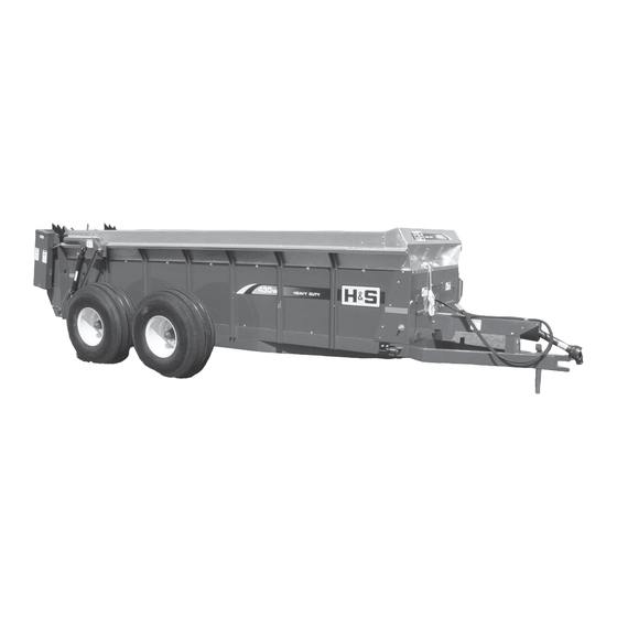
MANURE SPREADER
MANURE SPREADER
MANURE SPREADER
MANURE SPREADER
MANURE SPREADER
OPERA
OPERA T T T T T OR'S MANU
OPERA
OPERA
OPERA
Revision #1
430W Starting Serial #317196
H&S MANUFACTURING CO.,INC.
P.O. BOX 768 (715) 387-3414 FAX (715) 384-5463
430W
430W
430W
430W
430W
OR'S MANU
OR'S MANU
OR'S MANU AL
OR'S MANU
WARNING
Manufactured By
MARSHFIELD, WISCONSIN 54449
READ AND UNDERSTAND THIS MANUAL
BEFORE OPERATING THIS EQUIPMENT.
UNSAFE OPERATION OR MAINTENANCE OF
THIS EQUIPMENT CAN RESULT IN SERIOUS
INJURY OR DEATH.
HSMFG1012
AL
AL
AL
AL
Part #59781
Advertisement
Table of Contents

Related Manuals for H&S 430W


Summary of Contents for H&S 430W
- Page 1 BEFORE OPERATING THIS EQUIPMENT. UNSAFE OPERATION OR MAINTENANCE OF THIS EQUIPMENT CAN RESULT IN SERIOUS WARNING INJURY OR DEATH. Revision #1 430W Starting Serial #317196 HSMFG1012 Part #59781 Manufactured By H&S MANUFACTURING CO.,INC. P.O. BOX 768 (715) 387-3414 FAX (715) 384-5463...
-
Page 2: Table Of Contents
CONTENTS Warranty & Warranty Registration Card ..........1-2 Dealer Pre-Delivery Checklist . -
Page 5: Dealer Pre-Delivery Checklist
DEALER PRE-DELIVERY CHECK LIST AFTER COMPLETION, DEALER SHOULD REMOVE AND RETAIN FOR RECORDS After the Manure Spreader has been completely set-up, check to be certain it is in correct operating order before delivering to the customer. The following is a list of points to inspect. Check off each item as you have made the proper adjustments and found the item operating satisfactorily. - Page 6 Intentionally Left Blank...
-
Page 7: Dealer Delivery Checklist
DEALER DELIVERY CHECK LIST AFTER COMPLETION, DEALER SHOULD REMOVE AND RETAIN FOR RECORDS This check list that follows is an important reminder of valuable information that should be passed on to the customer at the time this Manure Spreader is delivered. Check off each item as you explain it to the customer. - Page 8 Intentionally Left Blank...
-
Page 9: Safety Information - Be Alert Symbol
SAFETY INFORMATION YOUR SAFETY ALERT! IS INVOLVED. THIS SYMBOL IS USED THROUGHOUT THIS BOOK WHENEVER YOUR PERSONAL SAFETY IS INVOLVED. TAKE TIME TO BE CAREFUL. REMEMBER: THE CAREFUL OPERATOR IS THE BEST OPERATOR. MOST ACCIDENTS ARE CAUSED BY HUMAN ERROR. CERTAIN PRECAUTIONS MUST BE OBSERVED TO PREVENT THE POSSIBILITY OF INJURY OR DAMAGE. -
Page 10: Safety Information - Explanation Of Safety Signs
SAFETY INFORMATION Keep signs in good condition. Immediately replace any missing or damaged signs. RECOGNIZE SAFETY INFORMATION This is the safety-alert symbol. When you see this symbol on your machine or in this manual, be alert to the potential for personal injury. Follow recommended precautions and safe operating practices. -
Page 11: Safety Decals
SAFETY INFORMATION... - Page 12 SAFETY INFORMATION -10-...
-
Page 13: Safety Information - Warning - Owner Must Read And Understand
SAFETY INFORMATION TRACTOR: This operators manual uses the term “Tractor” when identifying the power or the towing source. W A R N I N G TO PREVENT SERIOUS INJURY OR DEATH BEFORE YOU ATTEMPT TO OPERATE THIS EQUIPMENT, READ AND STUDY THE FOLLOWING INFORMATION. -
Page 14: Cap Screw Torque Values
-12-... -
Page 15: Set-Up & Assembly
SET-UP & ASSEMBLY Note: Determine right and left side of spreader by viewing it from the rear. If instructions or parts lists call for hardened bolts, refer to Cap Screw Torque Value page to identify. PREPARING MANURE SPREADER The Manure Spreader may be shipped without the wheels/tires installed. 1. -
Page 16: Preparing For Operation
PREPARING FOR OPERATION TRACTOR CONNECTIONS Tractor Hitch Fasten the spreader hitch to the drawbar with a hitch pin with 15-3/4” for 1000 RPM a safety locking device. Remove the weight from the jack (jack is not to be used when spreader is loaded). Remove jack from pipe mount and place on convenient storage mount located on the top of left hitch channel. -
Page 17: Operation
OPERATION EMERGENCY SHUTDOWN If a foreign object becomes lodged in the beater area and shears the shear bolt, disengage the PTO. Stop the tractor engine, remove the ignition key, and allow all mechanisms to stop before cleaning or working on the spreader. WARNING: Some photographs used in the following pages show guards or shields removed for clarification. - Page 18 OPERATION SPREADING - WITH OPTIONAL HYDRAULIC DRIVE Engage tractor PTO shaft slowly. Beater is always in the engaged position, therefore, engaging tractor PTO will automatically start beater. Raise the hydraulic tailgate. Open hydraulic valve on tractor connected to speed control valve on Manure Spreader. Control speed of apron by turning speed control handle clockwise to increase speed, counter-clockwise to decrease speed.
-
Page 19: Adjustments
ADJUSTMENTS DRIVE CHAIN To adjust front drive chain, loosen jam nut turn nut on adjusting rod (located at the right hand front side of spreader) clockwise. There should be 1/2” deflection at the center of the drive chain. Over tightening or too loose of a chain will result in excessive wear on the bearing, chain and sprockets. - Page 20 ADJUSTMENTS BEATER CLUTCH ADJUSTMENT It may be necessary to compensate for wear in the beater clutch and clutch control yoke. When properly adjusted the moveable jaw clutch should have one-quarter (1/4”) inch (distance C) between clutches when disengaged. To adjust, loosen jam nut (A) holding spring bracket. With beater disengaged (clean out position), tighten nut (B) against shifter lever bracket until the proper distance between clutch jaws is reached.
-
Page 21: Service
SERVICE SHEAR BOLTS - Main Drive Shields Removed for Clarity The beater and the apron drive are protected by one shear bolt located on the front end of the side drive shaft (left side of spreader). Two spare shear bolts are provided. Shearing of the bolts is normally due to foreign objects in the manure or starting the spreader PTO too quickly with high tractor RPM’s. -
Page 22: Optional Equipment
OPTIONAL EQUIPMENT REAR PAN The rear pan shown is optional equipment. UPPER BEATER An optional upper beater is available and will provide a more uniform spreading in heaped and heavily matted material. The upper beater may be used with hydraulic endgate. -20-... - Page 23 OPTIONAL EQUIPMENT HYDRAULIC DRIVE An optional hydraulic drive unit is available to convert from two speed to variable speed hydraulic drive. Hydraulic drive may be used as a two or four hose tractor hook-up. Front Control Panel Hydraulic Motor Shields Removed for Clarity -21-...
-
Page 24: Lubrication Guide
LUBRICATION GENERAL INFORMATION IMPORTANT: Catch and dispose of fluid per local waste disposal regulations whenever service is performed on hydraulic components, valves, cylinders, hoses, etc. GREASE FITTINGS There are numerous grease fittings on the spreader. The operator should become familiar with all lubrication points and establish a systematic routine to insure complete and quick lubrication of the machine. - Page 25 LUBRICATION GREASE ZERK LOCATION - Grease every 10 Hours A. (3) PTO Shaft H. (2) Tailgate Arms B. (2) Front jack shaft bearings. I. (2) Axle Pivot(Model 310) C. (2) Rear Drive Shaft J. (4) Axle Pivot (Model 370430) D. (1) Beater K.
-
Page 26: Trouble Shooting
TROUBLE SHOOTING WARNING: MAKE SURE THAT THE TRACTOR IS SHUT OFF AND THE SPREADER CAN NOT MOVE BEFORE SERVICING THE MANURE SPREADER. MAINTENANCE AND REPAIR SERVICE WORK TO BE PERFORMED BY A QUALIFIED SERVICE PERSON ONLY. TROUBLE... POSSIBLE CAUSE... POSSIBLE REMEDY... Beater Does Not Turn PTO Not Turning Engage Tractor PTO... -
Page 27: Decal Location
Danger - Never Allow Ride 093466 540 RPM DCAMB Amber Reflector DCRED Red Reflectors H71594 Model Decal for Top Beater 8405 Decal-430W Spreader Left 66"W x 7"H 8406 Decal-430W Spreader Right 69"W x 8" 8407 Decal-430W Spreader Front 48"W x 5"H -25-... - Page 28 DECAL LOCATION 12794 093020 11593C 1494K 1494K 11593A 11211176 UNDER 1494J SHIELD 3494A DCAMB 8405 71949A UNDER SHIELD 8407 54033 72203A 1494J 9194B DCAMB 71188H (TWO 1494A 1494A SPEED DECAL) 11599 1494B 093466 1494K 1494L 71494A 3187 (HYDRAULIC 82602 9194A 71188B 1494B DRIVE DECAL IF EQUIPPED) -26-...
-
Page 29: Decal Location
DECAL LOCATION H71594 1494H 111593A 111593C 093020 8407 1494B 1494J 3494A DCAMB 8406 DCAMB 1494B 9194A 11211176 1494A DCRED 3494A -27-... -
Page 30: Service Notes
SERVICE NOTES -28-... -
Page 31: Specifications
SPECIFICATIONS Top Flare Width......68’....68”....68” Inside Width. - Page 32 H&S MFG H&S MFG ..CO H&S MFG CO ..H&S MFG H&S MFG products approved for the FEMA FEMA FEMA FEMA FEMA SEAL OF Q SEAL OF Q U U U U U ALITY SEAL OF Q ALITY ALITY...
Need help?
Do you have a question about the 430W and is the answer not in the manual?
Questions and answers