Table of Contents
Advertisement
Quick Links
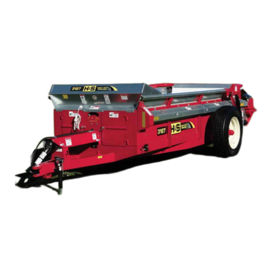
MANURE SPREADER
MANURE SPREADER
MANURE SPREADER
MANURE SPREADER
MANURE SPREADER
OPERA
OPERA T T T T T OR'S MANU
OPERA
OPERA
OPERA
Revision #03
560 Starting Serial #210086
660 Starting Serial #210046
H&S MANUFACTURING CO.,INC.
P.O. BOX 768 (715) 387-3414 FAX (715) 384-5463
560/660
560/660
560/660
560/660
560/660
OR'S MANU
OR'S MANU
OR'S MANU AL
OR'S MANU
WARNING
Manufactured By
MARSHFIELD, WISCONSIN 54449
READ AND UNDERSTAND THIS MANUAL
BEFORE OPERATING THIS EQUIPMENT.
UNSAFE OPERATION OR MAINTENANCE OF
THIS EQUIPMENT CAN RESULT IN SERIOUS
INJURY OR DEATH.
HSMFG0312
AL
AL
AL
AL
Part #72236
Advertisement
Table of Contents


Need help?
Do you have a question about the 560 and is the answer not in the manual?
Questions and answers