Page 1
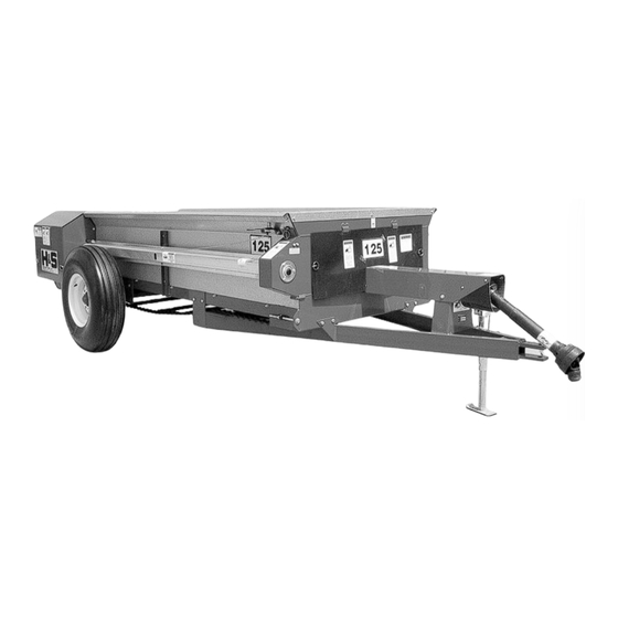
Heavy Duty Manure Spreader READ AND UNDERSTAND THIS MANUAL WARNING BEFORE OPERATING THIS EQUIPMENT. UNSAFE OPERATION OR MAINTENANCE OF THIS EQUIPMENT CAN RESULT IN SERIOUS INJURY OR DEATH. MODEL 80 & 125 PARTS & OPERATOR’S INSTRUCTIONS 10-25-2006 Manufactured By H&S MANUFACTURING CO., INC.
Page 2
Operation of Model 80 - Attaching to Tractor - Loading ....10 Spreading - Adjustments of Model 80 ....... . 11 Adjustments - Beater Control .
Page 3
AFTER COMPLETION, DEALER SHOULD REMOVE AND RETAIN FOR RECORDS H&S DEALER PRE-DELIVERY CHECK LIST After the Manure Spreader has been completely set-up, check to be certain it is in correct running order before delivering to the customer. The following is a list of points to inspect. Check off each item as you have made the proper adjustments and found the item operating satisfactorily.
Page 4
ALERT! YOUR SAFETY IS INVOLVED. THIS SYMBOL IS USED THROUGHOUT THIS BOOK WHENEVER YOUR PERSONAL SAFETY IS INVOLVED. TAKE TIME TO BE CAREFUL. REMEMBER: THE CAREFUL OPERATOR IS THE BEST OPERATOR. MOST ACCIDENTS ARE CAUSED BY HUMAN ERROR. CERTAIN PRECAUTIONS MUST BE OBSERVED TO PREVENT THE POSSIBILITY OF INJURY OR DAMAGE.
RECOGNIZE SAFETY INFORMATION This is the safety-alert symbol. When you see this symbol on your machine or in this manual, be alert to the poten- tial for personal injury. Follow recommended precautions and safe operating practices. UNDERSTAND SIGNAL WORDS A signal word—DANGER, WARNING, or CAUTION—is used with the safety-alert symbol.
Page 7
HELP AVOID AVOID INJURY • READ & UNDERSTAND TAND T T ORS MANUAL H & S MANUF F WITH MODEL AND SERIAL NUMBER. • UNDERSTAND ALL TAND ALL SAFETY WARNINGS AND WARNINGS AND FUNCTION OF CONTROLS. • KEEP SAFETY DEVICES IN PLACE AND WORKING. •...
Page 8
H&S MODELS 80 & 125 MANURE SPREADER W A R N I N G TO PREVENT SERIOUS INJURY OR DEATH BEFORE YOU ATTEMPT TO OPERATE THIS EQUIPMENT, READ AND STUDY THE FOLLOWING INFORMATION. IN ADDITION, MAKE SURE THAT EVERY INDIVIDUAL WHO OPERATES OR WORKS WITH THIS EQUIPMENT, WHETHER FAMILY MEMBER OR EMPLOYEE, IS FAMILIAR WITH THESE SAFETY PRECAUTIONS.
OPERATION MODEL 80 (FOR MODEL 125 SEE PAGE 14) 1. Check for proper assembly and adjustment and make sure that all bolts are tightened. Securely retighten after a few hours of operation, as bolts can loosen up on new machinery. Check wheel bolts upon delivery and periodically thereafter.
POWER AND speed greater than 540 RPM’s. SHUTTING OFF TRACTOR ENGINE. ADJUSTMENTS MODEL 80 (FOR MODEL 125 SEE PAGE 15) APRON Adjust the apron by tightening the adjusting bolts located at the front of the spreader until the apron chain rests lightly on top of the chain guides located below the axle.
Page 11
APRON DRIVE CHAIN Maintain proper tension on the apron drive chain. There should be 1/4 inch deflection at the side of the chain when properly adjusted. To adjust loosen bolt holding tightener. Slide tightener against drive chain and retighten bolt. Failure to maintain proper tension will result in excessive wear to chain and sprockets.
LUBRICATION GUIDE MODEL 80 (FOR MODEL 125 SEE PAGE 17) The operator should become familiar with all lubri- cation points and establish a systematic routine to insure complete and quick lubrication of the machine. DO NOT CLEAN DRIVE CHAINS–Lubricate the drive chains with a OR WORK ON THIS light machine oil.
Page 13
OPERATION MODEL 125 1. Check for proper assembly and adjustment and make sure that all bolts are tightened. Securely retighten after a few hours of operation, as bolts can loosen up on new machinery. Check wheel bolts upon delivery and periodically thereafter. Wheel bolts should be tightened at 60-65 ft./lbs. of torque. 2.
Page 14
LOADING In freezing weather make sure the apron chain is not frozen to the spreader floor. Also check to make sure that there are no chunks of manure frozen to the floor. Begin loading the spreader at the front end and work toward the rear until loading is completed. Loading this way permits the materials to be spread uniformly.
BEATER DRIVE Maintain proper tension on the beater and apron drive chains. There should be 1/4’’ deflection at the bottom center of each chain. Failure to maintain proper tension will result in undue stress to beater stub shaft and bearings. SHEAR BOLT The beater and apron drive are protected by one shear bolt.
Page 16
Keep the FIRST DISENGAGING gearbox filled to the oil level plug on the side of POWER AND the gearbox as shown, with #80 or #90 gear SHUTTING OFF lube. TRACTOR ENGINE. DRIVE CHAINS–Lubricate the drive chains with a light machine oil.
Start PTO slowly to avoid damage to the drive train. ATTACHED AT BOTH ENDS. • DRIVELINE SHIELDS THAT TURN FREELY ON DRIVELINE. OPTIONAL EQUIPMENT REAR PAN The rear pan is optional on the ModelS 80 &125 spreaders. MODEL 80 MODEL 125 -18-...
INSTRUCTIONS FOR ORDERING PARTS All service parts should be ordered through your authorized H&S dealer. He will be able to give you faster service if you will provide him with the following: 1. Model & Serial Number - Both can be located on the front PTO Bearing Support Mount. 2.
Page 19
DECAL LOCATION MODEL 80 Your H&S Manure Spreader was manufactured with operator safety in mind. Located on the manure spreader are various decals to aid in operation, and warn of danger or caution areas. Pay close attention to all the decals on your Manure Spreader.
Page 21
DECAL LOCATION MODEL 125 Your H&S Manure Spreader was manufactured with operator safety in mind. Located on the manure spreader are various decals to aid in operation, and warn of danger or caution areas. Pay close attention to all the decals on your Manure Spreader. DO NOT REMOVE ANY OF THESE DECALS.
Page 22
(Under Shield) Shields Removed For Clarity -23-...
Page 26
FIGURE 2 MODEL 125 SHIELDS, AXLE AND POLE ASSEMBLY ITEM PART NO. DESCRIPTION PTO Rubber Shield 12N1 Shield Clip Pin Front Shield Bracket 12N85 Front Poly Shield 12N86 Front Side Shield 12N4 Front Housing 12N5 Cover 12N6 Rear Housing Shield Bracket 12N87 Side Shield 12N8...
Page 28
FIGURE 3 MODEL 80 FRAME, BEATER & SHIELDS ITEM PART NO. DESCRIPTION 80N34 Front Panel 80N77 Right Spreader Side 80N79 Left Spreader Side 80N37 Side Shaft Shield 80N38 Front Side Shield Cover 80N80 Front Side Shield 80N40 Side Bearing Mount...
Page 34
FIGURE 6 MODEL 125 APRON, CHAIN, FLOOR & PAN ITEM PART NO. DESCRIPTION 12N52 Rubber Flap Angle 12N53 Rubber Flap Cotter Pin Pan Spacer 12N54 12N55 RH Pan Support 12N56 LH Pan Support 12N57 Trip Lever Plate 1/2’’ x 2’’ Bolt Spring Angle Spring Trip Lever Stop...
Page 35
FIGURE 7 MODEL 80 PTO PARTS ITEM PART NO. DESCRIPTION S225 Spring-Lok Repair Kit S379 Spring-Loc Yoke Assm. T274 12P Cross and Bearing Kit 80N88 Yoke and Shaft S206 Guard Repair Kit (Not Shown) 16SV283 Safety Sign 16SV384 Safety Sign 540 RPM...
Page 38
FIGURE 9 MODEL 80 & 125 GEAR BOX ITEM PART NO. DESCRIPTION Seal Bushing 12N98 36T Gear Capscrews (8) Drain Plug Gear Housing - Lower Expansion Plug Bushing Snap Ring 12N99 Low Speed Output Shaft 1/4’’ x 1-1/8’’ Key 5/16’’ x 1’’ Key...
Page 39
FIGURE 10 FIGURE 10 MODEL 80 OPTIONAL PAN 80 BUSHEL SPREADER ITEM PART NO. DESCRIPTION 12N52 Pan Angle 12N53 Pan Rubber 80N1 80N2 LH Pan Plate 80N3 RH Pan Plate 5N67 Pan Handle 80N82 Pan Handle Stop Pan Handle Spring...
Need help?
Do you have a question about the 80 and is the answer not in the manual?
Questions and answers