Table of Contents
Advertisement
Quick Links
TWO SPEED GEARBOX
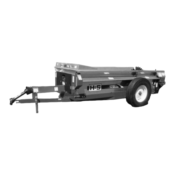
Heavy Duty Manure Spreader
WARNING
UNSAFE OPERATION OR MAINTENANCE OF THIS EQUIPMENT CAN RESULT IN SERIOUS
INJURY OR DEATH.
PARTS & OPERATOR'S
H&S MANUFACTURING CO., INC.
P.O. BOX 768 • (715) 387-3414 FAX (715) 384-5463
H
&
READ AND UNDERSTAND THIS MANUAL
BEFORE OPERATING THIS EQUIPMENT.
MODEL 175
INSTRUCTIONS
Manufactured By
MARSHFIELD, WISCONSIN 54449
S
9
8-1-2011
9-28-2009
Advertisement
Table of Contents

Subscribe to Our Youtube Channel
Related Manuals for H&S 175


Summary of Contents for H&S 175
-
Page 1: Warranty & Warranty Registration Card
Heavy Duty Manure Spreader WARNING READ AND UNDERSTAND THIS MANUAL BEFORE OPERATING THIS EQUIPMENT. UNSAFE OPERATION OR MAINTENANCE OF THIS EQUIPMENT CAN RESULT IN SERIOUS INJURY OR DEATH. MODEL 175 PARTS & OPERATOR’S INSTRUCTIONS 8-1-2011 9-28-2009 Manufactured By H&S MANUFACTURING CO., INC. -
Page 2: Table Of Contents
H&S MODEL 175 SPREADER PARTS AND OPERATOR’S MANUAL CONTENTS Warranty & Warranty Registration Card ......1-2 Dealer Pre-Delivery &... -
Page 3: Dealer Pre-Delivery & Delivery Checklist
AFTER COMPLETION, DEALER SHOULD REMOVE AND RETAIN FOR RECORDS H&S DEALER PRE-DELIVERY CHECK LIST After the Manure Spreader has been completely set-up, check to be certain it is in correct running order before delivering to the customer. The following is a list of points to inspect. Check off each item as you have made the proper adjustments and found the item operating satisfactorily. -
Page 5: Be Alert Symbol
ALERT! YOUR SAFETY IS INVOLVED. THIS SYMBOL IS USED THROUGHOUT THIS BOOK WHENEVER YOUR PERSONAL SAFETY IS INVOLVED. TAKE TIME TO BE CAREFUL. REMEMBER: THE CAREFUL OPERATOR IS THE BEST OPERATOR. MOST ACCIDENTS ARE CAUSED BY HUMAN ERROR. CERTAIN PRECAUTIONS MUST BE OBSERVED TO PREVENT THE POSSIBILITY OF INJURY OR DAMAGE. -
Page 6: Explanation Of Safety Signs
RECOGNIZE SAFETY INFORMATION This is the safety-alert symbol. When you see this symbol on your machine or in this manual, be alert to the poten- tial for personal injury. Follow recommended precautions and safe operating practices. UNDERSTAND SIGNAL WORDS A signal word—DANGER, WARNING, or CAUTION—is used with the safety-alert symbol. -
Page 7: Danger - Warning Signs
HELP AVOID AVOID INJURY • READ & UNDERSTAND TAND T T ORS MANUAL H & S MANUF F WITH MODEL AND SERIAL NUMBER. • UNDERSTAND ALL TAND ALL SAFETY WARNINGS AND WARNINGS AND FUNCTION OF CONTROLS. • KEEP SAFETY DEVICES IN PLACE AND WORKING. •... -
Page 9: Warning - Owner Must Read And Understand
H&S MODEL 175 MANURE SPREADER W A R N I N G TO PREVENT SERIOUS INJURY OR DEATH BEFORE YOU ATTEMPT TO OPERATE THIS EQUIPMENT, READ AND STUDY THE FOLLOWING INFORMATION. IN ADDITION, MAKE SURE THAT EVERY INDIVIDUAL WHO OPERATES OR WORKS WITH THIS EQUIPMENT, WHETHER FAMILY MEMBER OR EMPLOYEE, IS FAMILIAR WITH THESE SAFETY PRECAUTIONS. -
Page 10: Operation - Attaching To Tractor - Loading
OPERATION 1. Check for proper assembly and adjustment and make sure that all bolts are tightened. Securely retighten after a few hours of operation, as bolts can loosen up on new machinery. Check wheel bolts upon delivery and periodically thereafter. Wheel bolts should be tightened at 85-95 ft./lbs. of torque. 2. -
Page 11: Spreading - Adjustments
LOADING In freezing weather, make certain that hydraulic tail gate (if equipped with one) is not frozen to the sides or on the floor of the spreader. Make sure the apron chain is not frozen to the spreader floor or any lumps of manure are frozen to the floor. -
Page 12: Adjustments - Beater Control
DRIVE CHAIN To adjust front drive chain, slightly loosen bolts holding pillow block bearing at rear of front jack shaft. Loosen jam nut on tightener rod. Turn adjusting nut (located at the right hand front side of spreader) clockwise. There should be 1/2’’ deflec- tion at the center of the drive chain. -
Page 13: Lubrication Guide
APRON SPEED AND BEATER CONTROL One cable controls the beater and apron drive two speed gearbox. To compensate for wear or stretching of this cable adjust turnbuckle behind shield at left hand front of spreader. Refer to drawing to properly adjust manure spreader. Position speed control in HI Speed. - Page 14 LUBRICATION GUIDE (Continued) GREASE ZERK LOCATION A. (3) PTO shaft B. (2) Front jack shaft bearings C. (2) Side shaft D. (2) Rear drive shaft (LH side is a remote fitting) E. (1) Rear drive shaft shear sprocket F. (1) Beater bearing (RH side) G.
-
Page 15: Pto & Beater Instructions
LUBRICATION GUIDE (Continued) PTO ASSEMBLY – Care must be taken to keep the male and female driving elements well lubricated and free sliding. Failure to observe this precaution will result in excessive pres- sure being required to collapse or extend the assembly while subject to operating torque. -
Page 16: Optional Equipment
OPTIONAL EQUIPMENT REAR PAN/SEMI-LIQUID HYDRAULIC ENDGATE The rear pan shown below is optional equipment on the Model 175 and the semi-liquid hydraulic endgate (pictured below right) is also optional. Rear pan and hydraulic endgate may be used together on this model. -
Page 17: Service Notes
– SERVICE NOTES – -17-... -
Page 18: Decal Location & Identification
Warning - Do Not Operate 11599 Warning -Stay Clear of Leaks Amber Reflective H&S Patent Numbers 82602 Warning - Crushing Hazard 62003-175 Complete Set of Decals - Model 175 Paint - H & S Red ZX21 Gallon ZX22 Quart ZX23 Pint G W I... - Page 19 V (Behind Shield) Shields Removed for Clarity -19-...
- Page 20 FIGURE 1 -20-...
- Page 21 FIGURE 1 H&S MODEL 175 BEATER AND PAN ASSEMBLY ITEM PART NO. DESCRIPTION 23N1 5/16’’ x 5’’ GR.5 Bolt 23N2 Splined Beater Insert 1/2’’ x 1-1/4’’ GR.5 Bolt Lock Washer 17G2 Replacement Beater Comb 17G3 LH Beater Blade 17G4 RH Beater Blade 1/2’’...
- Page 22 FIGURE 2 -22-...
- Page 23 FIGURE 2 H&S MODEL 175 SPINDLE, HUB AND BOX PARTS ITEM PART NO. DESCRIPTION 17G144 Hub Cap Cotter Pin Washer 17G145 Outer Bearing 17G146 Outer Race 17G147 Hub Bolt 17G148 17G149 Inner Race 17G150 Inner Bearing 17G151 Seal 17G152 Spindle Right Hand...
- Page 24 FIGURE 3 -24-...
- Page 25 FIGURE 3 H&S MODEL 175 FRONT SHIELD AND DRIVE ASSEMBLY ITEM PART NO. DESCRIPTION Cable Guide U-Bolt 23N183 Rope 23N280 Shift Lever 23N281 Pivot Link Turnbuckle 23N282 Shifter Dog Grease Zerk 23N283 Stop Bracket S304 Washer 23N284 Shifter Dog Spring...
- Page 26 FIGURE 4 -26-...
- Page 27 FIGURE 4 H&S MODEL 175 BACK SHIELDS AND DRIVE ASSEMBLY ITEM PART NO. DESCRIPTION ITEM PART NO. DESCRIPTION BFR220 Cable Clamp 17G176 Shifter Shield 17G52 Back Side Shield 23N190 Shear Hub 17G175 Coupler Shield 17G64 Side Shaft 17G54 Front Side Shield...
- Page 28 FIGURE 5 -28-...
- Page 29 FIGURE 5 H &S MODEL 175 HYDRAULIC TAILGATE ITEM PART NO. DESCRIPTION 17G77 Tailgate Frame 17G78 Tailgate Pin 17G79 Tailgate Plywood 17G80 Tailgate Corner 17G81 LH Side Rubber 17G82 RH Side Rubber 17G83 Bottom Rubber 17G84 Tailgate Mounting Tube 23N108...
- Page 30 FIGURE 6 H&S MODEL 175 APRON CHAIN ASSEMBLY ITEM PART NO. DESCRIPTION 17G88 Drive Shaft Shield 3/8’’ x 1-3/8’’ Sq. Key 17G89 Drive Shaft 17G90 Spacer 17G91 Spacer 23N122 6T Sprocket 17G92 Apron Chain 15 Slats, 188 Links 17G93 Slat w/Att. Links T-Rod Standard Link 1/2’’...
- Page 31 FIGURE 7 H&S MODEL 175 HYDRAULIC CYLINDER ITEM PART NO. DESCRIPTION 23N142A Clevis Cap 23N143A Rod Cap 23N144 Piston 23N145A 23N146 Cylinder Tube 23N147 Tie Rod 23N148 Piston Nut 23N149 Plug 23N150A Rod Clevis 23N151 Seal Kit 23N111A Hydraulic Cylinder...
- Page 32 FIGURE 8 -32-...
- Page 33 FIGURE 8 H&S MODEL 175 GEARBOX ITEM PART NO. DESCRIPTION ITEM PART NO. DESCRIPTION 17G99 Upper Gear Housing 17G118 28T Gear w/Clutch 17G100 17G119 High-Speed Clutch S136 Seal 17G120 Worm Shaft 17G58 Vent Cap 3G19 Retaining Ring 23N288 Pipe Nipple...
- Page 34 FIGURE 9 H&S MODEL 175 PTO ASSEMBLY ITEM PART NO. DESCRIPTION 23N152 PTO Assembly Complete w/Shields 23N153 Machine Half PTO w/Shield G1R35 End Yoke Machine Half 14NW KIT Repair Kit 23N155 Yoke and Tube 24N26 Bearing Retainer 4N20 Nylon Bearing 23N156 Inner Guard Including Item #6 &...
- Page 35 FIGURE 10 H&S MODEL 175 OPTIONAL TOP BEATER ITEM PART NO. DESCRIPTION F114A Bearing Flange w/Zerk 45° F115 Bearing Bearing Flange Lock Collar 23N164 LH Stub Shaft 17G180 2nd Beater 17G186 RH Stub Shaft 5/16’’ x 1-3/8’’ Sq. Key 16T Sprocket...
-
Page 36: Service Notes
– SERVICE NOTES – -36-... -
Page 37: Specifications
Capacity (Old Rating) ........ - Page 38 S MFG. CO. & products approved for the FEMA SEAL OF QUALITY...
Need help?
Do you have a question about the 175 and is the answer not in the manual?
Questions and answers