OpenEye OE-C8213 User Manual
Indoor / outdoor ptz ip dome camera
Hide thumbs
Also See for OE-C8213:
- Quick start manual (8 pages) ,
- Hardware manual (8 pages) ,
- Quick start manual (2 pages)
Table of Contents
Advertisement
Quick Links
Advertisement
Table of Contents

Subscribe to Our Youtube Channel
Related Manuals for OpenEye OE-C8213


Summary of Contents for OpenEye OE-C8213
- Page 1 INDOOR / OUTDOOR PTZ IP DOME CAMERA USER MANUAL OE-C8213...
- Page 2 The information in this publication is provided “as is” without warranty of any kind. The entire risk arising out of the use of this information remains with recipient. In no event shall OPENEYE be liable for any direct, consequential, incidental, special, punitive, or other damages whatsoever (including without limitation, damages for loss of business profits, business interruption or loss of business information), even if OPENEYE has been advised of the possibility of such damages and whether in an action or contract or tort, including negligence.
-
Page 3: Important Safeguards
Important Safeguards 1. Read Instructions Read all of the safety and operating instructions before using the product. 2. Retain Instructions Save these instructions for future reference. 3. Attachments / Accessories Do not use attachments or accessories unless recommended by the appliance manufacturer as they may cause hazards, damage product and void warranty. - Page 4 Regulation This device complies with Part 15 of the FCC Rules. Operation is subject to the following two conditions: (1) this device may not cause harmful interference, and (2) this device must accept any interference received, including interference that may cause undesired operation. For more details information about recycling of this product, please contact your local city office, your household waste disposal service or the shop where you purchased the product.
-
Page 5: Table Of Contents
TABLE OF CONTENTS INTRODUCTION ..........................7 ..............................7 VERVIEW Product Features ............................. 7 CONTENTS ............................ 8 ..........................8 AMERA ONTENTS ..............................9 IMENSIONS ............................10 ONNECTIONS ......................11 ETUP AND ABLE ONNECTION Dome Cable Definition and Requirements ....................11 INSTALLATION ..........................15 .......................... - Page 6 Network Share ............................40 Recording Schedule ..........................42 Maintenance ............................44 Software ..............................45 ............................45 ICTURE ETTING Camera Setup ............................45 PTZ Setup ............................. 46 Motion Detection ........................... 46 Text Overlay ............................46 TV system .............................. 46 ............................ 46 TREAMING ETTING Video Resolution ............................
-
Page 7: Introduction
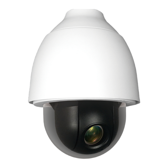
INTRODUCTION OVERVIEW OpenEye OE-C8213 IP PTZ camera provides users with crystal clear video thanks to 3MP resolution and 30x optical zoom. The cameras’ continuous 360º rotation and 190º tilt range make them a versatile PTZ solution for live monitoring environments. True WDR and a true day/night IR cut filter produce superior video in a variety of lighting conditions. -
Page 8: Contents
3-Pin Power 2-Pin Power Terminal Block Terminal Block (DC12V OE-C8213 PTZ Camera (AC 24V Use) Use) Security Torx Tool M4 Security Screw 14-Pin Alarm/Audio I/O... -
Page 9: Dimensions
DIMENSIONS 36847AD... -
Page 10: Connections
CONNECTIONS Connection Definition Power (DC12V) DC12V power connection RJ-45 For network and PoE+ connections Power Connector Power supply to camera for non-PoE networks (AC24V) For analog video output Audio/Alarm I/O Alarm, Audio and RS-485 I/O connections & RS-485 Connector Press the button with the proper tool for at least 20 Reset Button seconds to restore the camera to default settings. -
Page 11: Dome Setup And Cable Connection
For operation, the IP dome camera requires a network cable to carry the video signals to the remote viewing site and a power cable to power the dome. Cable Requirements For operation, the OE-C8213 can be powered with PoE+ and/or 24vAC is the heater is used. Power Wire Length Specifications Wire... - Page 12 Camera Cabling Considerations The OE-C8213 has an IP66 Outdoor rating to prevent water from entering the camera. However, proper installation is required for this rating. To ensure that the camera is as water resistant as possible, follow these tips: •...
-
Page 13: Power Connection
2. Connect ground wire to pin 2. 3. Connect NEGATIVE 24 volt AC power to pin 3. Note Be careful not to pull the cables improperly during installation. OpenEye suggests that you fasten the cables after installation is complete. Grounding Recommendation The GND (ground) wire must be directly connected to the middle pin of the 24vAC power connector. - Page 14 14-Pin Audio / Alarm Input / Output & RS-485 Connection Using the 14-pin connector, installers can connect 4 digital alarm inputs and 2 digital alarm outputs. The alarm pins are serviceable for connecting alarm input and output devices such as sensors, sirens, or flashing lights to the surveillance system.
-
Page 15: Installation
INSTALLATION OPTIONAL ACCESSORIES Threaded Mount Adapter Small Pole Mount Part Number: OE-CA821TMA Part Number: CA-510PMS Wall Mount Bracket (w/Anti-Drop) Large Pole Mount Part Number: CA-510W Part Number: CA-510PML Long Wall Mount Bracket (w/Anti-Drop) Part Number: CA510WL 50 cm Ceiling Pole Part Number: CA-510P50 25 cm Ceiling Pole Part Number: CA-510P25... -
Page 16: Installation Scenarios
The ceiling mount pole is available in two lengths: 25 cm and 50 cm. Note Ensure that the ceiling can support the weight of the dome camera and the ceiling pole. Items Needed Tools Needed • OE-C8213 IP Dome Camera • Drill Threaded Mount Adapter Screwdriver •... -
Page 17: Wall Mounting With Wall Mount Bracket
WALL MOUNTING WITH WALL MOUNT BRACKET Items Needed Tools Needed • OE-C8213 IP Dome Camera • Drill • Threaded Mount Adapter • Screwdriver • Wall Mount Bracket or Long Wall Mount Bracket Screws and Anchors for the • mounting surface (not supplied) 1. -
Page 18: Wall Mounting With Corner Mount
WALL MOUNTING WITH CORNER MOUNT The corner mount must be used in conjunction with the wall mount bracket. Items Needed Tools Needed OE-C8213 IP Dome Camera Drill • • • Threaded Mount Adapter • Screwdriver • Wall Mount Bracket Accessory Kit (OE-CALCL or OE-CALCS) •... -
Page 19: Pole Mounting
POLE MOUNTING The dome can be mounted on a pole with the small or large direct mounting accessory and a wall mount bracket. Items Needed Tools Needed OE-C8213 IP Dome Camera Drill • • Threaded Mount Adapter Screwdriver • •... -
Page 20: Network Camera Manager Software
NETWORK CAMERA MANAGER SOFTWARE OpenEye Network Camera Manager (NCM) is a software tool that allows you to quickly and easily connect and configure your OpenEye IP Cameras. This software allows you to assign IP addresses, manage users, configure video settings, and update firmware on multiple cameras at once. - Page 21 Launch from Apex Linux Platform 1. In the Apex Settings menu, click Launch Support Tools. 2. Click the Network Camera Manager icon. 36847AD...
-
Page 22: Camera Configuration
CAMERA CONFIGURATION DEVICE ADDRESSING The functions on the Device Addressing tab allow you to find, configure, and view network cameras. Finding Network Devices 1. Click Refresh to reload the Device List. 2. To narrow your search by Camera Model and Network Location, use the Model Filter and Networks dropdowns. -
Page 23: Setup & Configuration
2. Enter the Username and Password for the camera. The username and password are case sensitive. It is strongly recommended that the password be changed after the initial setup to prevent unauthorized access. The default username and password for OpenEye IP cameras are as follows. -
Page 24: Video Settings
VIDEO SETTINGS The Video Settings menu configures the camera’s basic settings, including frame rate, bitrate, and the streaming codec(s). 1. Use the dropdown menus to configure the Video Orientation, Sharpness, and Wide Dynamic Range. 2. Click Apply to save each selection. 3. -
Page 25: Live
LIVE Snapshot – Click the button, and a JPEG snapshot will automatically be saved in the appointed place. The default location is: C:\. Full Screen – This displays the live feed in full screen. Press ESC to close full screen. Note If you are using Windows Vista or 7, you will need to change the Snapshot location. -
Page 26: Setup
SETUP The Setup menu includes System Setting, Picture Setup, and Streaming Setting. Note The Setup menu displays limited setup options. For a complete list of setup options, see the Advanced section. SYSTEM SETTING Camera Name Host Name – The Host Name is used to identify the camera on your system. If camera-based Motion Detection is enabled, and is set to send alarm message by Mail/FTP, the host name entered here will display in the alarm message. -
Page 27: Ip Address
The MAC address is located on the IP Address tab, the bottom of each camera, and on the box label (OpenEye Network Camera Manager also displays the MAC address for identification). Record your camera’s MAC address for identification in the future. - Page 28 Secondary DNS – A secondary domain name server that backups the primary DNS. Note The Web Server port is also used in OpenEye Server Software. • Web Server port – Defines the port that Internet Explorer uses to connect over the web and view video.
-
Page 29: Picture Setup
Use the Camera Tab section to modify picture settings for the camera. The sample image will change as you modify the picture settings. Note These settings can drastically affect the camera image. OpenEye suggests that these settings are only modified by a CCTV professional, or at the instruction of a technical support representative. - Page 30 PTZ Setup Use the PTZ Setup tab to program Preset Points, Tours, and Auto Scan Paths via PTZ controls. Additionally, various camera settings including camera flip, privacy masks and RS485 settings. can be set here. Preset Up to 256 Preset points can be programmed for the camera. To create a Preset point: 1.
-
Page 31: Tilt Range
To run a scan path: Select the specified path from the list under Auto Scan Run and click Run. To stop running an Auto Scan Path, move the cursor to the live view pane and use the PTZ controls to move the camera in any direction. -
Page 32: Ptz Setting
Privacy Mask The Privacy Mask function helps avoid any intrusive monitoring. When you create a mask, it is suggested that you set it at least twice as big (height and width) than the masked object. The camera will assume the center of the selected view as a starting point. - Page 33 Speed by zoom – allows the camera to adjust the pant/tilt speed automatically using the internal algorithm when the zoom ration is changed. The rotating speed will become slower as the zoom ration gets larger. Auto Calibration – integrating servo feedback technology, the camera will calibrate and precisely return to the previous position without stalling when the deviation of dome pivot is detected.
-
Page 34: Streaming Settings
Add Detection Area 1. Use the Motion Detection dropdown to select a motion detection preset. 2. Select the Enable brush check box under Motion Region Paint and then use the cursor on the live view pane to highlight the desired motion detection area. 3. -
Page 35: Video Rotation
Bitrate – The default setting of the H.265/H.264 bitrate for Stream 1 / Stream 2 is 4096 kbit/s; for Stream 3 / Stream 4 is 2048 kbit/s. The setting range is from 512 to 10240, and the total bit rate should not exceed 26624 kbps. -
Page 36: Network Advanced
Refer to the IP Address section on page 27. DDNS DDNS (Dynamic Domain Name Service) is a service that allows a connection to an IP address using a hostname (URL) address instead of a numeric IP address. Most ISPs use Dynamic IP Addressing that frequently changes the public IP address of your internet connection;... -
Page 37: Network Security
SNMP Settings With Simple Network Management Protocol (SNMP) enabled, the camera can be monitored and managed remotely with a network management system. Contact your network administrator if you are not familiar with SNMP setup. UPnP (Universal Plug N’ Play) Enable UPnP – When enabled, the camera will appear in My Network Places on Windows computers running UPnP on the same network. -
Page 38: Alarm Application
ALARM APPLICATION The alarms menu is where alarm connections are configured. Alarm Switch – Designate when the alarm will be active; Off, On, or By Schedule. Alarm Type – Designate if the alarm is normally open or normally closed. Example: A door sticker consists of two contacts that are connected when under normal conditions. -
Page 39: Network Failure Detection
NETWORK FAILURE DETECTION Network Failure Detection – Turn the network Detection Switch On, Off, or On By Schedule. Detection Type – Designate the IP Address that will be tested and how often (in minutes). Triggered Action – Designate the actions that will occur upon Network Failure Detection. 36847AD... -
Page 40: Mail, Http And Ftp Setup
MICROSD CARD OpenEye IP cameras include an integrated microSD™ card slot that can be used to record video or images. The card slot is compatible with a microSD™ card up to 128GB. Device Information – Displays the storage total size and free space information of the included microSD™... - Page 41 Recording List – Displays a list of files saved to the card. You can delete files from the card, or save them to your local PC. 36847AD...
-
Page 42: Recording Schedule
RECORDING SCHEDULE The recording schedule allows you to set up scheduled recording to the microSD™ card or to Network Sharing. Recording This section allows you to define recording schedules for the camera. For continuous recording: 1. Select type of Recording Storage. •... - Page 43 Schedule This section allows you to establish schedules for recording. To create a schedule: 1. Select a Schedule set (1-10). 2. Check the desired week day check boxes. 3. Select Day or Night. 4. Designate a Start Time and Duration. 5.
-
Page 44: Maintenance
MAINTENANCE On the Maintenance page you can export the current configuration of the camera, or import the configuration for a camera. Use the factory default page to reset the IP Camera to factory default settings if necessary. Note Do not import configuration files from a different camera model. Configuration Export Configuration: 1. -
Page 45: Software
SOFTWARE Note Make sure the software upgrade file is available before starting the software upgrade. 1. Click Choose File and find the upgrade file. Note Do not change the file name, or the system will fail to find the file. 2. -
Page 46: Ptz Setup
the light level detected by the camera reaches the threshold, the camera will automatically switch to Day/Night Mode. (0=darker, 10=brighter) IR Light Compensation – the camera can prevent the center object close to the camera from being too bright caused by IR illumination Noise Reduction –... -
Page 47: Audio
RTSP over HTTP – Tunnels RTSP by HTTP. Able to pass through firewalls between the camera and the viewer. MJPEG over HTTP – Streams a sequence of JPEG images by HTTP. Able to pass through firewalls between the camera and the viewer. Multicast mode –... -
Page 48: Camera Specifications
CAMERA SPECIFICATIONS Camera Model OE-C8213 Maximum Resolution 3MP (2065x1553) Image Sensor Sony 3M - 1/2.8" Progressive CMOS Video Compression MJPEG / H.264+ / H.265 Frame Rate 30 IPS @ 3M H.264+ ONVIF Profile S Streaming Up to x4 simultaneous streams... -
Page 49: Ptz Specifications
PTZ SPECIFICATIONS Camera Model OE-C8213 Control Type PTZ control via network only Zoom Factor Presets Preset Accuracy ±.0225º Preset Speed 5º ~ 400º / second Pattern Tour (Group) Auto Scan Privacy Mask Home Function Preset, Pattern, Tour, Auto-scan Auto Flip... - Page 50 All rights reserved. No part of this publication may be reproduced by any means without written permission from OpenEye. The information in this publication is believed to be accurate in all respects. However, OpenEye cannot assume responsibility for any consequences resulting from the use thereof. The information contained herein is subject to change without notice.
Need help?
Do you have a question about the OE-C8213 and is the answer not in the manual?
Questions and answers