Table of Contents
Advertisement
Quick Links
Download this manual
See also:
User Manual
Advertisement
Table of Contents

Related Manuals for OpenEye OE-C7312-AWR


Summary of Contents for OpenEye OE-C7312-AWR
- Page 1 Outdoor IP Dome Camera User Manual Camera Accessories OE-C7312-AWR CA-510G CA-510PML CA-510W CA-510PMS CA-510C CA-510PA25 CA-510P25 CA-510PA50 CA-510P50 www.openeye.net...
- Page 2 The information in this publication is provided “as is” without warranty of any kind. The entire risk arising out of the use of this information remains with recipient. In no event shall OPENEYE be liable for any direct, consequential, incidental, special, punitive, or other damages whatsoever...
-
Page 3: Important Safeguards
Important Safeguards Read Instructions Read all of the safety and operating instructions before using the product. Retain Instructions Save these instructions for future reference. Attachments / Accessories Do not use attachments or accessories unless recommended by the appliance manufacturer as they may cause hazards, damage product and void warranty. Installation Do not place or mount this product in or on an unstable or improperly supported location. - Page 4 Installation and Storage Install electricity wiring carefully. Please note that input electricity to the unit is at tolerance of DC 12V/AC 24V ± 10%. The camera is capable of surge protection; ensure AC power model unit is grounded appropriately against damage by heavy current or electric shock.
- Page 5 Warning DANGEROUS HIGH VOLTAGES ARE PRESENT INSIDE THE ENCLOSURE. DO NOT OPEN THE CABINET. REFER SERVICING TO QUALIFIED PERSONNEL ONLY. Caution C A U T I O N RISK OF ELECTRIC SHOCK DO NOT OPEN CAUTION: TO REDUCE THE RISK OF ELECTRIC SHOCK, DO NOT REMOVE COVER (OR BACK).
-
Page 6: Standard Warranty
OpenEye will warrant all otherwise out of warranty replacement parts and repairs for 90 days from the date of OpenEye shipment. The above warranty is the sole warranty made by OpenEye and is in lieu of all other warranties by OpenEye express and implied, including without limitation the warranties of merchantability and fitness for a particular purpose. -
Page 7: Table Of Contents
Introduction .................... 11 Overview ........................11 Product Features ...................... 11 Getting Started ..................12 Box Contents ........................ 12 Camera Overview ......................13 Dimensions ....................... 13 Connections ......................14 Installation ....................15 Power and Ethernet Connection ................... 15 Power Connection ....................15 Ethernet Cable Connection .................. - Page 8 System Setting ......................27 Camera Name ......................27 IP Address ........................ 28 Get IP an Address Automatically (DHCP) ............28 Use Static IP Address ..................29 IPv6 Address Configuration ................30 User Setup ........................ 30 Admin Password ....................30 Add User ......................30 Delete User ......................
- Page 9 SNMP Settings ..................... 40 UPnP (Universal Plug N’ Play) ................40 Network Security ...................... 41 HTTP ........................41 IP Filtering ......................41 IEEE 802.1XSEAP-TLS ..................41 Alarm Application ...................... 42 Tampering and Network Failure Detection ............... 43 Mail, HTTP and FTP Setup ..................44 SD Card ........................
-
Page 10: Introduction
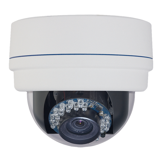
The OE-C7312-AWR is an outdoor IP Dome, capable of providing real-time high-quality video. This camera is capable of dual streaming, delivering multiple streams to multiple clients with options for streaming in MJPEG and H.264. With a compact and sophisticated mechanical design the Outdoor IP Dome Camera is easy to install and the vandal proof cover can protect the camera from heavy damage. -
Page 11: Getting Started
Before proceeding, please check that the box contains the items listed here. If any item is missing or has defects, DO NOT install or operate the product and contact your dealer for assistance. OE-C7312-AWR Camera BNC cable Self Tapping Screws... -
Page 12: Camera Overview
Before installing or connecting the dome camera, please refer to this section and complete preparations for dome setup and all switch settings. Dimensions Diameter – 151 mm (5.9 inches) Height – 130 mm (5.12 inches) 32616AB... -
Page 13: Connections
Connections Description Note Network RJ45 Power (AC 24v) AC 24 1 (AC 24v) AC 24 2 DC 12v (GND) DC 12v (+) Analog video output microSD Card Slot For video recording storage Alarm & Audio I/) Alarm In (-) Alarm in (+) Alarm out (-) Alarm out (+) Audio out (R) -
Page 14: Installation
When using 12vDC or 24vAC power, refer to the pin definition table in the Camera Overview > Connections section for the proper 2-wire connection. OpenEye recommends against using more than one power source at a time. Do not use a PoE power source when providing the camera with 12vDC or 24vAC power. -
Page 15: Camera Installation
You can install your Outdoor IP Dome Camera directly onto a wall or ceiling. The wall or ceiling must have enough strength to support the camera. Use the supplied Torx tool to unscrew the two Torx screws on the side of the dome cover and remove the dome cover. - Page 16 Use a Phillips screwdriver to remove the mounting plate from the base of the camera. Use the mounting plate to mark the location you want to install your camera on the ceiling. Mark the location of the holes for the mounting screws as well as the hole for the camera cables, as needed.
- Page 17 10. Use the OpenEye IP Finder software to locate the camera on the network and complete configuration of the camera. 11. Manually aim the camera as necessary. 12. Replace the Inner Dome cover. 13. Replace the dome cover, aligning the arrow mark on the dome cover with the one on the housing, and then screw the two Torx screws on the dome tightly to fasten the dome cover to the camera base.
-
Page 18: Network Camera Manager Software
IP addresses, manage users, configure video settings, and update firmware on multiple cameras at once. The Network Camera Manager software is pre-installed on all OpenEye Recorders, and included on the software CD with all OpenEye IP cameras. It is also available for download on the OpenEye website. Installation... -
Page 19: Starting Network Camera Manager
After installing the program on your PC or laptop, open the program to begin configuring your cameras. To access Network Camera Manager on an OpenEye recorder, you must operate the recorder in Windows Mode. In the Live Screen, click Exit. -
Page 20: Camera Configuration
Device Addressing The functions on the Device Addressing tab allow you to find, configure, and view network cameras. Click Find Devices on the Device Addressing tab. To narrow your search by Camera Model, Project, or Camera Name, select your desired criteria from the appropriate lists. 32616AB... -
Page 21: Viewing A Network Camera
Enter the Username and Password for the camera. The username and password are case sensitive. It is strongly recommended that the password be changed after the initial setup to prevent unauthorized access. The default username and password for OpenEye IP cameras are as follows. Username – admin Password – 1234 The viewer software is now opened in Internet Explorer. -
Page 22: Setup & Configuration
Connecting to the Camera Locate the camera on the IP Finder list. Double-click the camera to open the Viewer software in your web browser. Click Browse in the pop-up window. Log in to the camera with the appropriate User Name and Password. The default User name is admin and the default Password is1234. -
Page 23: Connecting Over The Internet
There are some challenges with connecting to OpenEye IP cameras over WAN (internet) connections because the camera streams video over RTSP. RTSP is an excellent protocol for media and is now used on many IP cameras (including OpenEye) as the default streaming option. -
Page 24: Viewer Software
To access the setup menu, you need to install the viewer software on your PC or recorder. The viewer software will install automatically the first time you connect to the camera. If your internet browser doesn’t install the viewer software, check the security settings or ActiveX controls and plug-in settings. -
Page 25: Live
Full Screen – This will display the live feed in full screen. Snapshot – Click the button, and a JPEG snapshot will automatically be saved in the appointed place. The default location is: C:\. If you are using Windows Vista or 7, you will need to change the Snapshot location. -
Page 26: System Setting
The Setup menu includes System Settings, Picture Setup, and Streaming Settings. The Setup menu displays limited setup options. For a complete list of setup options, see the Advanced section. Camera Name Host Name – The Host Name is used to identify the camera on your system. -
Page 27: Ip Address
Every network device has a unique Media Access Control (MAC) address that can be used for identification. The MAC address is located on the bottom of each camera, and on the box label (OpenEye Network Camera Manager also displays the MAC address for identification). Record your camera’s MAC... -
Page 28: Use Static Ip Address
Click Apply to confirm the new setting. When using static IP address to log in to the IP Camera, you can access it either through OpenEye IP Finder software or type the IP address directly in the address bar of your Internet Explorer. -
Page 29: Ipv6 Address Configuration
IPv6 Address Configuration To enable IPv6 select Enable IPv6 and click Save. See your network administrator if you are unsure of your network configuration. User Setup Manage the password for the Administrator account. To change the administrator password: Type a new Administrator Password, and then type again to confirm the password. -
Page 30: Modify User
Select the user name on the User Name list. Click Edit. In the resulting window, modify the Password and/or feature permissions. Click Save. For security reasons, every time the user properties are opened the access check boxes are automatically cleared. Make sure you select any user access options each time you edit the user properties. -
Page 31: Picture Setup
Use the Camera Tab section to modify picture settings for the camera. The sample image will change as you modify the picture settings. These settings can drastically affect the camera image. OpenEye suggests that these settings are only modified by a CCTV professional, or at the instruction or a technical support representative. -
Page 32: Picture Adjustment
Each of the Picture Adjustment settings is set to the recommended default. Brightness – Adjust the image’s brightness on the camera. The Backlight value is adjustable from 0 (dim) ~ +20 (brightest). Sharpness – Increasing the sharpness level can make the image looked sharper;... -
Page 33: Add Detection Window
Use the Motion Detection dropdown to select a motion detection preset. Click Add. The selected motion detection square will be red. Arrange and size the motion detection window as desired. Click Save. Click to select the desired motion detection window. Click Delete. -
Page 34: Streaming Settings
Video Resolution The camera provides eight codec options under video resolution (two single streaming options, two sets of dual streaming options, two sets of tri- streaming options, and two sets of quad-streaming options): H.264 Only MJPEG Only H.264 + H.264 ... -
Page 35: Video Orientation
OpenEye recommends setting the GOP to be approximately twice the frame rate (e.g.: if the frame rate is 10 IPS, then set the GOP to 20). ... -
Page 36: Video Frame Rate
Video Frame Rate Setting the camera to transmit fewer frames can save bandwidth. Use the Frame Rate Control screen to adjust the frame rate of each stream. Each of the MJPEG and H.264 streams can have a separate frame rate setting from 1 to 30 frames per second. -
Page 37: Video Compression
Video Compression You can select an MJPEG / H.264 compression mode on the video compression page appropriate for your application. You can also select to display compression inflation on the Live Screen. MJPEG compression settings include: High compression, low bitrate, low quality ... -
Page 38: Advanced
Network Setup The Network Setup settings will automatically be set at the recommended default after the camera connection is made. DDNS (Dynamic Domain Name Service) is a service that allows a connection to an IP address using a hostname (URL) address instead of a numeric IP address. Most Internet Service Providers use Dynamic IP Addressing that frequently changes the public IP address of your internet connection;... -
Page 39: Snmp Settings
With Simple Network Management Protocol (SNMP) enabled, the camera can be monitored and managed remotely with a network management system. Contact your network administrator if you are not familiar with SNMP setup. Enable UPnP – When enabled, the camera will appear in My Network Places on Windows computers running UPnP on the same network. -
Page 40: Network Security
Network Security The camera can send alarm messages to a specific Hypertext Transfer Protocol (HTTP) site when motion is detected or when the sensor input is activated. You can assign alarm messages to up to two HTTP sites. IP Filtering allows you limit access to your IP cameras by IP address. You can “Allow” or “Deny”... -
Page 41: Alarm Application
Alarm Application The alarms menu is where alarm connections are configured. Alarm Switch – Designate when the alarm will be active; Off, On, or By Schedule. Alarm Type – Designate if the alarm is normally open or normally closed. NOH –... -
Page 42: Tampering And Network Failure Detection
Tampering and Network Failure Detection Tampering Alarm – Turn the Tampering Alarm On, Off, or On By Schedule. Tampering Duration – Designate the amount of time (in seconds) that tampering must occur in order for a Tampering Alarm to activate. Triggered Action –... -
Page 43: Mail, Http And Ftp Setup
SD Card All OpenEye IP cameras include an integrated microSD™ card slot that can be used to record video or images. The card slot is compatible with a microSD™ card up to 16GB. Load Device Information – Displays the storage total size and free space information of the included microSD™... -
Page 44: Network Share
Network Share Network Share is a network protocol that runs a variety of different system platforms, allowing for file sharing between computers operating on Windows and computers operating on Unix. This serves as an additional storage type. Configuration requires the host IP address, share name, and credentials. Once configured, cameras can record events to the network share. -
Page 45: Recording Schedule
Recording Schedule The recording schedule allows you to set up scheduled recording to the microSD™ card or to Network Sharing. This section allows you to define recording schedules for the camera. For continuous recording: Select type of Recording Storage. microSD card™: save recorded data to the microSD™... - Page 46 This section allows you to establish schedules to use in other section. To create a schedule: Select a Schedule set (1-10). Check the desired week day check boxes. Select Day or Night. Designate a Start Time and Duration. Click Save. 32616AB...
-
Page 47: Interval Recording
Interval recording allows you to record in consistent intervals and save the files for later viewing. Turn Interval Recording On or Off. Designate the Time Interval (seconds). Designate the Trigger Action using the appropriate checkbox, and then use the dropdown menus to further manage the Trigger Action. Type a file name, and then choose how the file name is multiplied for multiple files. -
Page 48: Maintenance
Maintenance On the Maintenance page you can export the cameras current configuration, or import the configuration for a camera. Use the factory default page to reset the IP Camera to factory default settings if necessary. Do not import configuration files from different models of cameras. Export Configuration: Check the appropriate boxes for information that you want exported. -
Page 49: Software
Software Make sure the software upgrade file is available before starting the software upgrade. Click Browse and find the upgrade file. Do not change the file name, or the system will fail to find the file. Select the file name from the list under Step 2. Click Upgrade. -
Page 50: Streaming Setting
Audio Audio Input Grain – sets the amplification that the camera applies to the incoming audio before transmitting. Audio Output Delay – Sets a delay in the audio transmission. This is used when there is significant lag in video transmission to help sync the audio and video. Volume –... -
Page 51: Specifications
Model OE-C7312-AWR Maximum Resolution 1080p (2MP) Son1/2.8” CMOS Image Sensor Video Compression H.264 / MJPEG 30 IPS @ 1080P [1920 x 1080 / 2MP] 30 IPS @ 1280 x 1024 (1.3MP) Frame Rate 30 IPS @ 720P [1280 x 720 / 1MP]... - Page 52 Model OE-C7312-AWR Active / Passive Cooling Passive 12.4W Max Power Consumption 19.4W Max (Heater ON) Rated Amperage 0.91A (24vAC) / 2.1A (12vDC) Input Voltage 12vDC / 24vAC / PoE+ (802.3at) PoE Class IR Range Up to 50 ft (15 m)
- Page 54 © 2015 OpenEye All rights reserved. No part of this publication may be reproduced by any means without written permission from OpenEye. The information in this publication is believed to be accurate in all respects. However, OpenEye cannot assume responsibility for any consequences resulting from the use thereof.
Need help?
Do you have a question about the OE-C7312-AWR and is the answer not in the manual?
Questions and answers