Table of Contents
Advertisement
Quick Links
Istruzioni per installazione, uso e manutenzione
Installations-, Bedienungs- und Wartungsanleitung
Installation, use and maintenance instructions
Manuel d'entretien
Bruciatori di gas
I
Gasbrenner
D
Gas burners
GB
Brûleurs gaz
F
Funzionamento modulante
Modulierender Betrieb
Modulating operation
Fonctionnement modulant
CODICE - CODE
3898340
3898350
3898442
3898452
3899142
3899152
3911080
3911090
MODELLO - MODELL
MODEL - MODELE
RS 300/EV BLU
RS 300/EV BLU
RS 400/EV BLU
RS 400/EV BLU
RS 500/EV BLU
RS 500/EV BLU
RS 800/EV BLU
RS 800/EV BLU
TIPO - TYP
TYPE - TYPE
849 T2
849 T2
850 T2
850 T2
856 T2
856 T2
887 T2
887 T2
2916391 (2) - 09/2008
Advertisement
Table of Contents

Subscribe to Our Youtube Channel
Related Manuals for Riello Burners RS 800/EV BLU


Summary of Contents for Riello Burners RS 800/EV BLU
- Page 1 3898442 RS 400/EV BLU 850 T2 3898452 RS 400/EV BLU 850 T2 3899142 RS 500/EV BLU 856 T2 3899152 RS 500/EV BLU 856 T2 3911080 RS 800/EV BLU 887 T2 3911090 RS 800/EV BLU 887 T2 2916391 (2) - 09/2008...
-
Page 3: Table Of Contents
INDICE INHALT Dati tecnici ........pagina 4 Technische Angaben . -
Page 4: Dati Tecnici
Codice 3010379 (RS 300-400/EV BLU) Codice 3010455 (RS 500/EV BLU) • KIT INVERTER Codice 3010468 (RS 800/EV BLU) Codice 3010469 (solo per la Russia) • KIT AZL (unità di visualizzazione e taratura) • RAMPE GAS SECONDO NORMA EN 676: vedere a pagina 22. -
Page 5: Elenco Modelli Disponibili
Diretto/Inverter 3898442 - 3898452 RS 500/EV BLU 400V-50Hz Diretto/Inverter 3899142 - 3899152 RS 800/EV BLU 400V-50Hz Diretto/Inverter 3911080 - 3911090 PAESE DI DESTINAZIONE CATEGORIA GAS AT - CH - CZ - DK - EE - ES - FI - GB - GR - HU - IE - IS - IT - LT - LV - NO - PT - SE... -
Page 6: Technische Angaben
Code 3010378 • KIT O Code 3010379 (RS 300-400/EV BLU) Code 3010455 (RS 500/EV BLU) • KIT INVERTER Code 3010468 (RS 800/EV BLU) Code 3010469 (nur für Rußland) • KIT AZL (Anzeige und Einstellungeinheit) GASARMATUREN GEMÄß NORM EN 676: •... -
Page 7: Verzeinis Der Modelle
Direkt//Inverter 3898442 - 3898452 RS 500/EV BLU 400V-50Hz Direkt//Inverter 3899142 - 3899152 RS 800/EV BLU 400V-50Hz Direkt//Inverter 3911080 - 3911090 LAND GASKATEGORIE AT - CH - CZ - DK - EE - ES - FI - GB - GR - HU - IE - IS - IT - LT - LV - NO - PT - SE... -
Page 8: Technical Data
• O Code 3010379 (RS 300-400/EV BLU) Code 3010455 (RS 500/EV BLU) • INVERTER KIT Code 3010468 (RS 800/EV BLU) Code 3010469 (olny for Russia) • AZL KIT (display and operating unit) GAS TRAIN ACCORDING TO REGULATION EN 676 •... -
Page 9: List Of Available Models
Direct/Inverter 3898442 - 3898452 RS 500/EV BLU 400V-50Hz Direct/Inverter 3899142 - 3899152 RS 800/EV BLU 400V-50Hz Direct/Inverter 3911080 - 3911090 DESTINATION COUNTRY GAS CATEGORY AT - CH - CZ - DK - EE - ES - FI - GB - GR - HU - IE - IS - IT - LT - LV - NO - PT - SE... -
Page 10: Données Techniques
• KIT O Code 3010379 (RS 300-400/EV BLU) Code 3010455 (RS 500/EV BLU) • KIT INVERTER Code 3010468 (RS 800/EV BLU) Code 3010469 (seulement pour Russia) • KIT AZL (unité d’affichage et de réglage) RAMPES GAZ SELON LA NORME EN 676 •... -
Page 11: Modèles Disponibles
DESIGNATION BRULEURS SERIE RS Série : Combustible : Gas naturel Fioul Fioul / Méthano Fioul Dimension Régulation : Came électronique Came électronique et moteur à fréquence variable (avec Variateur de fréquenc Soupape proportionnelle air/ gaz Émission : Classe 1 EN267 - EN676 Classe 2 EN267 - EN676 Classe 3 EN267 - EN676 Classe 2 EN267... -
Page 12: Descrizione Bruciatore
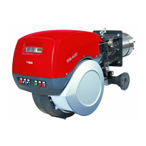
DESCRIZIONE BRUCIATORE (A) 1 Anelli di sollevamento 2 Girante 3 Motore ventilatore 4 Servomotore serranda aria 5 Presa di pressione gas testa di combustione 6 Testa di combustione 7 Elettrodo di accensione 8 Disco di stabilità fiamma 9 Cofano quadro elettrico 10 Servomotore farfalla gas 11 Ingresso aria ventilatore 12 Manicotto... -
Page 13: Burner Description
BRENNERBESCHREIBUNG (A) BURNER DESCRIPTION (A) DESCRIPTION BRULEUR (A) 1 Heberinge 1 Lifting eyebolts 1 Anneaux de soulèvement 2 Gebläserad 2 Fan 2 Turbine 3 Gebläsemotor 3 Fan motor 3 Moteur ventilateur 4 Luftklappestellantrieb 4 Air gate valve servomotor 4 Servomoteur volet d’air 5 Gasdruckentnahmestelle 5 Gas pressure test point 5 Prise de pression gaz à... -
Page 14: Imballo - Peso
RS 400/EV BLU 1325 521 164 313 588 DN80 775 867 373 1175 1055 320 RS 500/EV BLU 1325 521 164 370 588 DN80 775 867 357 1175 1055 320 RS 800/EV BLU 1325 582 164 363 588 DN80 940 867 418 1175 1055 320... -
Page 15: Packaging - Weight
M 18 x 60 1 - Ecran thermique 1 - Wärmeschild 1 - Gas elbow (RS 800/EV BLU only) 26) (A) p. 12 4 - Vis pour fixer la bride du brûleur à la 4 - Schrauben für die Befestigung des Bren- 8 - Studs to secure the gas elbow to the mani- chaudière: M 18 x 60... -
Page 16: Campi Di Lavoro
RS 300/EV BLU = 500 kW RS 400/EV BLU = 950 kW RS 500/EV BLU = 1000 kW RS 800/EV BLU = 1200 kW Attenzione: il CAMPO DI LAVORO è stato rica- vato alla temperatura ambiente di 20 °C, alla... -
Page 17: Firing Rates
RS 500/EV BLU = 1000 kW RS 500/EV BLU = 1000 kW RS 500/EV BLU = 1000 kW RS 800/EV BLU = 1200 kW RS 800/EV BLU = 1200 kW RS 800/EV BLU = 1200 kW Important: The FIRING RATE area values Attention: La PLAGE DE PUISSANCE a été... -
Page 18: Installazione
M 18 filettati può essere tracciata utilizzando lo RS 500/EV BLU M 18 schermo termico a corredo del bruciatore. RS 800/EV BLU M 18 LUNGHEZZA BOCCAGLIO (B) La lunghezza del boccaglio va scelta secondo le D455 indicazioni del costruttore della caldaia e, in ogni caso, deve essere maggiore dello spessore della porta della caldaia, completa di refrattario. -
Page 19: Installation
INSTALLATION INSTALLATION INSTALLATION KESSELPLATTE (A) BOILER PLATE (A) PLAQUE CHAUDIERE (A) Die Abdeckplatte der Brennkammer wie in (A) Drill the combustion chamber locking plate as Percer la plaque de fermeture de la chambre de gezeigt vorbohren. Die Position der Gewinde- shown in (A). -
Page 20: Posizione Elettrodi
POSIZIONE ELETTRODI (A) Elettrodo - Elektrode Sonda - Fühler Controllare che la sonda e l’elettrodo siano posi- Electrode - Electrode Probe - Sonde zionati come in fig. (A). REGOLAZIONE TESTA DI COMBU- STIONE (B) Il servomotore serranda aria 4)(A)pag. 12, oltre a variare la portata d’aria in funzione della richiesta di potenza, attraverso un levismo varia la regolazione della testa di combustione. -
Page 21: Position Of Electrodes
POSITION DER ELEKTRODEN (A) POSITION OF ELECTRODES (A) POSITION DES ELECTRODES (A) Kontrollieren Sie, ob Sonde und Elektrode wie in Make sure that the electrode and the probe are Contrôler si les électrodes sont positionnées Abb. (A) ausgerichtet sind. positioned as shown in figure (A). comme sur la fig. -
Page 22: Linea Alimentazione Gas
LINEA ALIMENTAZIONE GAS (A) La rampa del gas è predisposta per essere col- legata alla destra del bruciatore, tramite la flan- gia 1)(A). Qualora fosse necessario collegarla alla sinistra del bruciatore, svitare dadi e viti 3) e 4), togliere la flangia cieca 2) e la relativa guarnizione ed applicarle alla flangia 1) rimontando dadi e viti. -
Page 23: Gas Line
GASZULEITUNG (A) GAS LINE (A) LIGNE ALIMENTATION GAZ (A) Die Gasarmaturen können mit dem Flansch The gas train is to be connected on the right of La rampe gaz est prévue pour être reliée à la 1)(A) rechts am Brenner angebracht werden. the burner, by flange 1) (A). - Page 24 PRESSIONE GAS Importante Gas train La pressione alla testa del bruciatore da tabella 8 - 10 Pressure P1 butterfly + (A) è riferita a zero in camera di combustione; mbar mbar Adaptor per la pressione reale, misurata con un mano- MBC-1200 MBC-1900 MBC-3100...
- Page 25 GASDRUCK GAS PRESSURE PRESSION DU GAZ Wichtig Important Important Der Druck am Brennerkopf in Tabelle (A) The pressure at the head of the burner - from La pression à la tête du brûleur (tableau A) se bezieht sich auf einen Wert von Null in der table (A) - refers to zero in the combustion réfère à...
-
Page 26: Regolazioni Prima Dell'accensione
REGOLAZIONI PRIMA DELL'ACCENSIONE La regolazione della testa di combustione è già stata descritta a pag. 20. Altre regolazioni da fare sono: - Aprire le valvole manuali poste a monte della rampa del gas. - Regolare il pressostato gas di minima all'ini- zio scala. -
Page 27: Adjustment Before First Firing
EINSTELLUNGEN VOR DER ZÜNDUNG ADJUSTMENTS BEFORE FIRST FIRING REGLAGES AVANT L'ALLUMAGE Die Einstellung des Flammkopfs ist bereits auf Le réglage de la tête de combustion a déjà été Adjustment of the combustion head has been Seite 20 beschrieben worden. décrit page 20. illustrated on page 20. -
Page 28: Regolazione Aria Comburente
REGOLAZIONE ARIA COMBURENTE La sincronizzazione combustibile/comburente viene fatta con i relativi servomotori (aria e gas) attraverso la memorizzazione di una curva di taratura per mezzo della camma elettronica. E’ consigliabile, per ridurre le perdite e per avere un ampio campo di taratura, regolare i servomotori al massimo della potenza utilizzata, il più... -
Page 29: Combustion Air Adjustment
EINSTELLUNG DER VERBRENNUNGSLUFT COMBUSTION AIR ADJUSTMENT RÉGLAGE DE L’AIR COMBURANT Kraftstoff-/Verbrennungsluft-Synchronisie- Fuel/combustion air must be synchronized with La synchronisation combustible/comburant se rung erfolgt mit den jeweiligen Stellantrieben the relevant servomotors (air and gas) by stor- fait avec les servomoteurs correspondants (air (Luft und Gas) durch die Speicherung einer ing a setting curve by means of the electronic et gaz) en mémorisant une courbe de réglage à... -
Page 30: Pressostato Aria
è installato in maniera "differen- ziale", cioè collegato con due tubi alle relative prese di pressione “+” e “-” 22)-23)(A)p.12. Sul bruciatore RS 800/EV BLU il pressostato aria è installato in "assoluto", cioè collegato solo alla presa di pressione “+” 22)(A)p.12. -
Page 31: Air Pressure Switch
MAXIMUM GAS PRESSURE SWITCH (B) die Druckentnahmestelle “+” 22)(A) S.12 ange- Adjust the maximum gas pressure switch after Sur le brûleur RS 800/EV BLU, le pressostat air schlossen. having performed all the other burner adjust- est installé de manière “absolue”, c'est-à-dire, ments with the pressure switch set at the end of connecté... -
Page 32: Manutenzione
MANUTENZIONE Combustione Effettuare l'analisi dei gas di scarico della com- µA bustione. Gli scostamenti significativi rispetto al precedente controllo indicheranno i punti dove più attenta dovrà essere l'operazione di manu- tenzione. D3097 Fughe di gas Controllare che non vi siano fughe di gas sul condotto contatore-bruciatore. -
Page 33: Maintenance
WARTUNG MAINTENANCE ENTRETIEN Verbrennung Combustion Combustion Die Abgase der Verbrennung analysieren. The optimum calibration of the burner requires Pour obtenir un réglage optimal du brûleur, il Bemerkenswerte Abweichungen im Vergleich an analysis of the flue gases. Significant differ- faut effectuer l'analyse des gaz d'échappement zur vorherigen Überprüfung zeigen die Stelle ences with respect to the previous measure- de la combustion à... -
Page 34: Funzionamento Bruciatore
FUNZIONAMENTO BRUCIATORE (A) ACCENSIONE REGOLARE ORDNUNGSGEMÄSSES ZÜNDEN (secondi) (Sekunden) 1 - Termostato 2 - Motore NORMAL FIRING ALLUMAGE REGULIER 3 - Serranda aria (seconds) (secondes) 4 - Trasformatore d'accensione 5 - Valvola 6 - Fiamma 7 - Blocco SPEGNIMENTO DEL BRUCIATORE IN FUN- ZIONAMENTO Se la fiamma si spegne accidentalmente in fun- zionamento si ha il blocco del bruciatore entro... -
Page 35: Burner Operation
BRENNERBETRIEB (A) BURNER OPERATION (A) FONCTIONNEMENT BRULEUR (A) 1 - Thermostat 1 - Thermostat 1 - Thermostat 2 - Motor 2 - Motor 2 - Moteur 3 - Luftklappe 3 - Air gate valve 3 - Volet d'air 4 - Zündtransformator 4 - Ignition transformer 4 - Transformateur d'allumage 5 - Ventil... -
Page 36: Sistema Di Regolazione Aria/Combustibile E Modulazione Potenza
SISTEMA DI REGOLAZIONE ARIA/COM- BUSTIBILE E MODULAZIONE POTENZA GENERALITÀ Il sistema di regolazione aria/combustibile, e di modulazione della potenza, che equipaggia i bruciatori serie RS/EV realizza, in un unico dispositivo di controllo, una serie di funzioni inte- grate per la totale ottimizzazione energetica e operativa del bruciatore, sia in caso di funziona- mento singolo che in combinazione con altre unità... -
Page 37: Air/Fuel Control And Power Modulation System
SYSTEM FÜR DIE LUFT-/BRENNSTOFF- AIR/FUEL CONTROL POWER SYSTEME DE REGLAGE AIR/ COMBUS- REGELUNG UND DIE LEISTUNGSMO- MODULATION SYSTEM TIBLE ET MODULATION DE LA PUIS- DULATION SANCE GENERAL INFORMATION ALLGEMEINES The air/fuel and power modulation system GENERALITES Das System für die Luft-/Brennstoffregelung und installed on RS burner series provides, a set of Le système de réglage air/ combustible et de die Leistungsmodulation, mit dem die Brenner... -
Page 38: Collegamenti Elettrici
COLLEGAMENTI ELETTRICI PASSAGGIO CAVI DI ALIMENTAZIONE E COLLEGAMENTI ESTERNI DURCHGANG FÜR VERSORGUNGSKABEL UND EXTERNE VERBINDUNGEN Prima di effettuare qualsiasi operazione di ENTRY FOR POWER CABLES AND EXTERNAL LEADS manutenzione, pulizia o controllo: PASSAGE DES CÂBLES D’ALIMENTATION ET BRANCHEMENTS EXTERNES Togliere l’alimentazione elettrica al bruciatore, agendo sull’interruttore generale dell’impianto. -
Page 39: Electrical Wiring
ELEKTRISCHE ANSCHLÜSSE ELECTRICAL WIRING RACCORDEMENTS ÉLECTRIQUES Vor dem Ausführen jeglicher Wartungs-, Rei- Before carrying out any maintenance, clean- Avant d'effectuer toute opération d'entretien, nigungs- oder Prüfarbeiten: ing or checking operations: nettoyage ou contrôle: Schalten Sie die Stromversorgung Disconnect the electricity supply Couper l'alimentation électrique du des Brenners durch Betätigen des from the burner by means of the... -
Page 40: Schema Quadro Elettrico
Appendice - Anhang - Appendix - Annexe Schema quadro elettrico - Schaltplan - Layout of electric panel board - Schéma tableau électrique INDICE - INHALT - CONTENTS - INDEX Indicazione riferimenti - Bezugangabe References layout - Indication références Schema unifilare di potenza - Eindrahtiges Leistungsschema Layout of unifilar output - Schéma unifilaire de puissance Schema funzionale - Betriebsschema Functional diagram - Schéma de fonctionnement... - Page 54 LEGENDA SCHEMI ELETTRICI ZEICHENERKLÄRUNG SCHEMEN Camma elettronica Elektronischer Nocken Modulo O tipo PLL.. Modul des Typs PLL.. Unità di visualizzazione e taratura Display und operative Einheit Ingresso in corrente DC 4...20 mA Eingang in Gleichstrom DC 4...20 mA Ingresso in corrente DC 4...20 mA per modifica Eingang in Gleichstrom DC 4...20 mA für die Ände- setpoint remoto rung des Fern-Sollwertes...
- Page 55 KEY TO ELECTRICAL LAYOUT LÉGENDE SCHÉMAS ELECTRIQUE Electronic cam Came électronique module tipo PLL.. Module O type PLL Display and operating unit Unité d’affichage et de réglage DC input 4...20 mA Entrée avec courant DC 4...20 mA DC input 4...20 mA for modifying the remote set- Entrée avec courant DC 4...20 mA pour décalage point valeur de consigne à...
- Page 56 RIELLO S.p.A. I-37045 Legnago (VR) Tel.: +39.0442.630111 http:// www.riello.it http:// www.rielloburners.com Con riserva di modifiche - Änderungen vorbehalten! - Subject to modifications - Sous réserve de modifications...
Need help?
Do you have a question about the RS 800/EV BLU and is the answer not in the manual?
Questions and answers