Table of Contents
Advertisement
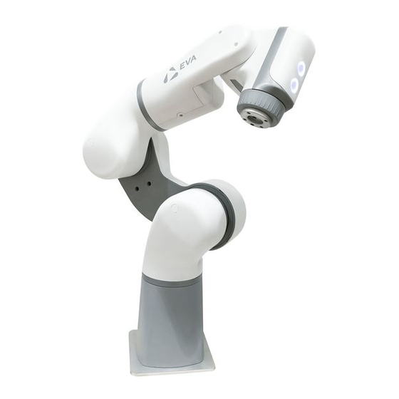
Eva Robotic Arm
Technical Reference User Manual
Version 1.0 - November 2018
The goal of this manual is to provide helpful information on the particulars of
Eva's
software, electronics and mechanics.
It does not contain comprehensive safety or risk information.
Before reading this manual, attempting to set up or operate the robot,
ensure you read and understand the separate safety manual and carry out a
risk assessment.
Download the latest version of this manual from https:/ /automata.tech
Advertisement
Table of Contents

Subscribe to Our Youtube Channel
Related Manuals for Automata Eva

Summary of Contents for Automata Eva
- Page 1 It does not contain comprehensive safety or risk information. Before reading this manual, attempting to set up or operate the robot, ensure you read and understand the separate safety manual and carry out a risk assessment. Download the latest version of this manual from https:/ /automata.tech...
-
Page 2: Table Of Contents
Electronic Interfaces Base Interface 1. Emergency Stop Connection 2. Reserved Stop Connection 3. Base I/O 4. Power Input 5. USB x 2 6. Ethernet Head Interface Mechanical Overview Dimensions & Axes Ratings & Limitations Getting the Most Out Of Eva... -
Page 3: Installing The Robot
Installing the robot Physical Setup In the box you will find Eva, an emergency stop switch and a power supply (with cables for each), a safety manual, and a user manual. Consult the safety manual for information on proper installation. -
Page 4: Tooling
Tooling Eva has an aluminium flange, or toolplate for attaching tools such as grippers or sensors. It has an ISO 9409-1 designation of 40-4-M6. This means it uses 4x M6 threaded holes arranged in a circular pattern, 40 mm in diameter. Refer to the drawing for detailed dimensions. - Page 5 Once connected, it’s possible to configure the robot to connect to another wifi access point or an ethernet network with a static IP. If Eva detects it has lost its connection, or has been configured with invalid settings, it will continue to at- tempt to connect for three minutes, before rolling back to the default access point and ethernet configuration.
- Page 6 The user must provide the SSID and Passphrase for the chosen network. Eva must also be assigned a unique Static IP, and a valid Netmask and Gateway in order to connect. On a home network, a typical Netmask and Gateway might be 255.255.255.0 and 192.168.1.1 respectively.
-
Page 7: Updating The Robot
Updating the Robot Download the latest Eva software and firmware packages from https:/ /automata.tech. To update the robot, navigate to the config page of Choreograph and take ownership. Drag and drop the relevant robot update package (or select ‘upload and install’) to the Software Update section of the page. -
Page 8: Controlling The Robot
Controlling the Robot Ways of interfacing As long as Eva remains online and errorless, it will execute any valid instruction from the device (such as a computer or tablet) with Robot Ownership. The simplest way to take ownership and send instructions to the robot is with Choreograph - a simple user interface accessible with your web browser. -
Page 9: Waypoints
Waypoints There are three ways to create waypoints: Press and hold the backdriving button on the head to release the brakes and physically manipulate the robot into a desired position. Release this button and press the waypoint button to create a waypoint. This will be picked up by the device with robot ownership (see: Installing the robot - Powering On and Connecting). -
Page 10: Waypoints
When a waypoint is selected, a new wheel menu will open: These icons: Make a copy of the waypoint Add a text label to the waypoint Delete the waypoint Move the waypoint to a new absolute position specified by XYZ coordinates, relative to the base of the robot Move the robot (real or virtual, depending on ownership) to this waypoint Close the menu... -
Page 11: The Timeline
Timeline at the bottom of the screen. The timeline reflects the actual actions Eva will take when the current toolpath is uploaded and executed. Any waypoints in the 3D viewer that are not present on the timeline will not affect the real robot, although they will be saved along with the timeline in the toolpath file. -
Page 12: Waypoints
The remainder of this toolbar deals with the properties of the toolpath: Reassign numbers to waypoints based on the order in which they were created Reassign numbers to waypoints based on the order they first appear on the timeline Open the toolpath settings menu, dealing with global speed and analog I/O modes The total duration of the timeline is displayed, based on current settings Simulate the toolpath;... -
Page 13: Waypoints
Right click on any waypoint in the timeline to change its properties: There are three types of trajectories between waypoints: Joint Space trajectories - represented by circles on the timeline - instruct the robot to move to the waypoint in a way that is ‘natural’ for the joints Linear trajectories - represented by squares on the timeline - instruct the robot to move its end-effector to the waypoint in a straight line. -
Page 14: Executing & Monitoring Toolpaths
Executing and Monitoring Toolpaths When Choreograph has robot ownership, it can send instructions to the robot. Note that the active toolpath in the robot memory is not necessarily the same as the toolpath shown in Choreograph. New toolpaths must be uploaded to the robot memory before they can be executed. -
Page 15: Programming With Choreograph
Programming with Choreograph Communicating with other devices Dragging the output icon onto the timeline opens a dialog box, asking for a specific electronic output pin and a value. When the toolpath is executed and this waypoint is reached, your chosen signal will be sent to this pin. Some tools require signals from more than one pin to take action. - Page 16 Conditional Branches Dragging the conditional branch icon onto the timeline creates a new branch, starting with a conditional waypoint. If the condition is true, any waypoints along this branch will be executed. If the condition is false, the branch will be skipped (ie: the central, empty branch will be chosen).
-
Page 17: Programming With The Api
Programming with the API After setting up Eva for the first time with Choreograph and creating a user pro- file, it’s possible to generate an API token from the user profile menu. A quality control application could be programmed as follows: A) Use Choreograph to create and save three toolpaths: Picking up a component and showing it to a measuring device. -
Page 18: Electronic Interfaces
Eva’s emergency stop function. This port is designed for a DPDT, 2NC e-stop push button switch conforming to IEC 60947-5-5, such as the button provided with Eva, or the ABB CEPY1-1001. The interface is a standard A-coded circular M8 female connector (IEC 61076-... - Page 19 This port is not in use, and is reserved for future expansion. Download the latest software, along with the latest version of this manual from https:/ /automata.tech. 3. Base I/O The connector pins are spring terminated. Press and hold the orange tab to retract the spring and insert a stripped wire end, then release the orange tab to engage the spring and lock the wire in place.
- Page 20 B) Digital Inputs Beneath the power pins are four digital input pins. These are 24 V IEC 61131-2 Type-3 current sinking inputs, for use with PNP type sensors or outputs. The robot and the outputting device should share a common ground, to ensure all signals are referenced to the same level.
- Page 21 These general purpose digital outputs can source up to 625 mA of current. They can be used to drive equipment like electromagnetic relays directly or for communication with other PLC systems. Signal Voltage Output Current (Base outputs) 625 mA Current (Tool outputs) 100 mA D) Analog Inputs There are two non-differential, single ended analog inputs on the base I/O, able...
- Page 22 E) Analog Outputs There are two non-differential, single ended analog outputs on the base I/O, configurable as current (4 - 20 mA) or voltage (0 - 10 V) mode. The mode can be specified in Choreograph, or via API calls. Base Ao1 (Pin21) Base Ao2 (Pin 23) GND (Pin 23)
-
Page 23: Usb X
4. Power Input Plug Eva into an RCD-protected ordinary mains socket with the provided power supply. It has the following specifications: Meanwell GST280A24 - C6P 100-240 VAC 50/60 Hz Output: 24 V, 11.67 A, 280 W MAX 5. USB x 2 These ports are not in use, and are reserved for future expansion. - Page 24 The control buttons are each surrounded by an LED ring. The colours of these rings indicate robot status: Both lights white = System Idle Both lights green = Toolpath Running Backdriving button green, Waypoint button white = Backdriving Mode Both lights yellow = Fault detected Tool Port The tool port uses a circular M8 female connector.
- Page 25 The digital output and analog input pins on the head I/O are configured differently from the pins on the base I/O. The two digital output pins can source 100 mA of current each, while the single 24 V power pin on the tool port can source a maximum of 1 A. This is shared with the digital outputs and so there may be less than 1 A available at the 24 V pin depending on your configuration.
-
Page 26: Mechanical Overview
Mechanical Overview Dimensions and Axes... -
Page 27: Ratings & Limitations
Eva achieves movement and maintains its position with six revolute joints: Each axis has its own mechanical brakes. These are engaged by default, and disengaged when the robot is instructed to move. A manual brake release is present in axes 2, 3 and 5. Consult the safety manual to learn how to carry out this procedure. - Page 28 It’s therefore essential to keep the workspace dry and dust free. Eva’s peak power consumption is 280 W. Power is sourced from a 24 VDC power supply. Beside the hard limits specified for each axis above, the robot software is programmed to resist movement as it approaches these limits.
-
Page 29: Getting The Most Out Of Eva
Getting the most of EVA When programming precise applications, mathematics is likely to give better results than backdriving and relying on the human eye Individual toolpaths can be exported as Base64, decoded into Javascript, edited and imported back to the robot computer Don’t backdrive aggressively - this could cause a hard stop and wear out the... - Page 32 Automata Technologies Limited Unit 4, Holford Yard Bevin Way London WC1X 9HD 020 3603 4590 support@automata.tech...
Need help?
Do you have a question about the Eva and is the answer not in the manual?
Questions and answers