
Related Manuals for Endress+Hauser OUSAF11


Summary of Contents for Endress+Hauser OUSAF11
- Page 1 Products Solutions Services BA00474C/07/EN/16.16 71330142 Operating Instructions OUSAF11 Optical sensor for the measurement of VIS/NIR absorption...
-
Page 3: Table Of Contents
Spare parts ......23 Return ......23 Endress+Hauser... -
Page 4: Document Information
Document information OUSAF11 Document information Warnings Structure of information Meaning This symbol alerts you to a dangerous situation. DANGER Failure to avoid the dangerous situation will result in a fatal or serious injury. Causes (/consequences) Consequences of non-compliance (if applicable) ‣... -
Page 5: Symbols On The Product
OUSAF11 Document information Symbols on the product Symbol Meaning Reference to device documentation Endress+Hauser... -
Page 6: Basic Safety Instructions
Repairs not described in the Operating Instructions provided may only be carried out directly by the manufacturer or by the service organization. Designated use The OUSAF11 sensor measures the VIS/NIR absorption of liquids. The sensor is suitable for use in a wide range of applications , such as: • Interphase detection •... -
Page 7: Product Safety
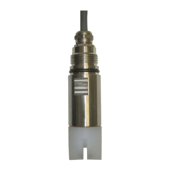
The relevant regulations and European standards have been observed. Product description Sensor design A0021712 1 Design of OUSAF11 Process connection (e.g. external thread) Sensor shaft Sensor head Endress+Hauser... -
Page 8: Measuring Principle
Product description OUSAF11 Measuring principle Light absorption The measuring principle is based on the Lambert-Beer law. There is a linear dependency between the absorption of light and the concentration of the absorbing substance: A = -log(T) = ε T = I/I T ... -
Page 9: Incoming Acceptance And Product Identification
OUSAF11 Incoming acceptance and product identification Incoming acceptance and product identification Incoming acceptance Verify that the packaging is undamaged. Notify your supplier of any damage to the packaging. Keep the damaged packaging until the matter has been settled. Verify that the contents are undamaged. -
Page 10: Scope Of Delivery
You will receive information on each feature (selected option) of the order code. Scope of delivery The scope of delivery consists of the following : • OUSAF11 sensor • Operating Instructions Ordering the sensor together with a transmitter: If you select the calibration option in the Product Configurator for the transmitter, the complete measuring system (transmitter, sensor, cable) is factory-calibrated and shipped as one package. -
Page 11: Installation
Installation Installation Installation conditions 5.1.1 Measuring system An optical measuring system comprises: • OUSAF11 sensor (photometer) • Transmitter, for example Liquiline CM44P • Sensor fixed cable A0029243 3 Example of a measuring system with a photometer sensor CM44P transmitter... - Page 12 Installation OUSAF11 5.1.2 Dimensions 149.1 (5.87) 139.0 135.5 (5.47) (5.33) 38.1 (1.5) A0021260 4 Design and dimensions in mm (inch) Submersible sensor Tri-Clamp or VARIVENT process connection Sensor with external thread 5.1.3 Mounting angles The sensor can be installed up to the horizontal in an assembly, support or suitable process connection.
- Page 13 OUSAF11 Installation A0029248 5 Mounting angles Permitted mounting angle: 0 to 180° 5.1.4 Mounting in pipes Detail A Detail A 90° A0029259 6 Permitted and unacceptable installation positions in pipes Endress+Hauser...
-
Page 14: Mounting The Sensor
Installation OUSAF11 Comply with the following conditions. Otherwise you run the risk of damaging the measuring point or obtaining incorrect measured values. ‣ The diameter of the pipe must be at least 50 mm (2"). ‣ Install the sensor in places with consistent flow conditions. -
Page 15: Post-Installation Check
Prior to commencing connection work, ensure that no voltage is present on any cable. Connecting the sensor The sensor is connected to the transmitter using the pre-terminated or labeled sensor fixed cable. A0029261 8 OUSAF11 fixed cable CM44P terminal CVM40 terminal Cable color Assignment V1.1... -
Page 16: Lamp Voltage
Electrical connection OUSAF11 Lamp voltage Sensor version Lamp type Lamp voltage [V] OUSAF11-xxxxx Incandescent lamp 4.9 ± 0.1 Ensuring the degree of protection Only the mechanical and electrical connections which are described in these instructions and which are necessary for the required, designated use, may be carried out on the device delivered. -
Page 17: Commissioning
OUSAF11 Commissioning Commissioning Function check Before first commissioning, check if: ‣ the sensor is correctly installed ‣ the electrical connection is correct. Calibrating/adjusting the sensor Measuring points consisting of a photometer sensor and a transmitter are adjusted at the factory. Normally adjustment is not required when commissioning for the first time. -
Page 18: Clean Sensor
Maintenance OUSAF11 Maintenance checklist • Replace lamp The lamp is typically replaced after 8000 to 10 000 operating hours (→ 26). • Replace O-rings in contact with the medium The replacement of O-rings in contact with the medium depends on the specific requirements of the process. - Page 19 OUSAF11 Maintenance NOTICE Incorrect turning The cables can be damaged and the sensor no longer functions ‣ Only turn the shaft. Never turn by the sensor head! ‣ Make sure that the cable is not twisted. Hold the sensor head firmly in position and unscrew the sensor shaft from the sensor head.
-
Page 20: Replacing The O-Ring
Maintenance OUSAF11 Remove the lamp from the fitting and replace it with a new one. Use a paper towel to insert the new lamp. Without graphics: Once you have inserted the new lamp, clean it with a paper towel and ethanol, if available. - Page 21 OUSAF11 Maintenance NOTICE Incorrect turning The cables can be damaged and the sensor no longer functions ‣ Only turn the shaft. Never turn by the sensor head! ‣ Make sure that the cable is not twisted. Hold the sensor head firmly in position and unscrew the sensor shaft from the sensor head.
- Page 22 Maintenance OUSAF11 If necessary, sever the cable tie on the sensor cable. There is a new cable tie in the spare parts kit which you can use to ensure strain relief on the cable once you re-insert the lamp and detector unit.
-
Page 23: Repairs
The product must be returned if repairs or a factory calibration are required, or if the wrong product was ordered or delivered. As an ISO-certified company and also due to legal regulations, Endress+Hauser is obliged to follow certain procedures when handling any returned products that have been in contact with medium. - Page 24 Technical data OUSAF11 10.1 Assembly Flexdip CYH112 • Modular holder system for sensors and assemblies in open basins, channels and tanks • For Flexdip CYA112 water and wastewater assemblies • Can be affixed anywhere: on the ground, on the capstone, on the wall or directly onto railings.
- Page 25 OUSAF11 Technical data 11.3 Process 11.3.1 Process temperature 0 to 90 °C (32 to 194 °F) continuous Max. 130 °C (266 °F) for 2 hours 11.3.2 Process pressure Max. 10 bar (150 psi) absolute, at 20 °C (68 °F) (For version with Tri-Clamp or VARIVENT process connection)
- Page 26 Technical data OUSAF11 11.4 Mechanical construction 11.4.1 Dimensions → 12 11.4.2 Weight Approx. 0.8 kg (1.8 lbs) 11.4.3 Materials Sensor head FEP (Fluorinated ethylene propylene) Sensor shaft Stainless steel 316L O-ring EPDM Cable connector ends Nickel-plated brass 11.4.4 Process connections Depends on version: •...
- Page 27 Mounting the sensor ....14 Nameplate ..... . 9 Endress+Hauser...
- Page 28 *71330142* 71330142 www.addresses.endress.com...
Need help?
Do you have a question about the OUSAF11 and is the answer not in the manual?
Questions and answers