
Related Manuals for Endress+Hauser OxyMax W COS 41


Summary of Contents for Endress+Hauser OxyMax W COS 41
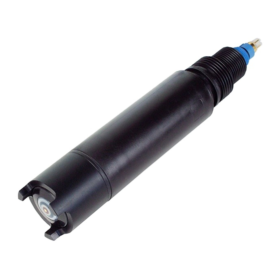
- Page 1 OxyMax W COS 41 BA 284C/07/en/05.01 No. 51506691 Sensor for Measuring Dissolved Oxygen Operating Instructions Quality made by Endress+Hauser ISO 9001...
-
Page 3: Table Of Contents
OxyMax W COS 41 Contents Safety instructions Commissioning ........ -
Page 4: Safety Instructions
• Measuring point faults may only be remedied by authorised and trained personnel. • If faults cannot be repaired, the sensor must be taken out of service and secured against unintentional commissioning. • Repairs may only be carried out by the manufacturer or by the Endress+Hauser serv- ice organisation. Endress+Hauser... -
Page 5: Operational Safety
If the device requires repair, please send the sensor clean (see page 18) to the appro- priate Endress+Hauser sales offices. Please use the original packaging where possible. Please add the filled in »Declaration of contamination« (copy the last but one page of this manual) to the packing of the sensor and add it also to the shipping documents. -
Page 6: Identification
– 1 sealing kit COY 31-OR with 3 O-rings – 6 abrasive sheets • Operating Instructions BA 284C/07/en If you have questions, please contact your supplier or your nearest Endress+Hauser sales office (see the back page of this Operating Instructions). Endress+Hauser... -
Page 7: Installation
OxyMax W COS 41 3 Installation Installation Measuring device A complete measuring system comprises: • Oxygen sensor COS 41 • Oxygen transmitter Liquisys M COM 223/253-DX/DS Optional: • Universal suspension assembly support CYH 101 for immersed operation • Immersion assembly COA 110 or DipFit W CYA 611 or flow assembly FlowFit W COA 250 or retractable assembly Probfit W COA 461 •... -
Page 8: Installation Conditions
3 Installation OxyMax W COS 41 Installation conditions 3.2.1 Installation dimensions Ø40 Fig. 3.2: Dimensions COS 41 Fig. 3.3: COS 41 with TOP 68 plug-in head and fixed cable version TOP 68 plug-in cable Endress+Hauser... -
Page 9: Installation Location And Position
OxyMax W COS 41 3 Installation Installation location and position The sensor can be installed up to the horizontal in an assembly, support or a suitable process connection (Fig. 3.4). Other angles are not permissible. Do not install the sen- sor overhead. - Page 10 3 Installation OxyMax W COS 41 3.3.1 Installation examples Immersed operation For large basins, where sufficient installation distance is required from the basin edge, it is advisable to use the upright post and chain assembly (Figs. 3.5 and 3.6). The free swinging of the immersed assembly practically rules out vibrations from the upright post.
- Page 11 OxyMax W COS 41 3 Installation Fig. 3.7: Universal assembly support CYH 101-D or E Weather protection cover Dummy plug Upright post square pipe stainless steel AISI 304 Transverse pipe stainless steel AISI 304 Star handle Velco fastener Immersion tube...
- Page 12 3 Installation OxyMax W COS 41 To aid installation in strongly fluctuating water levels, e.g. in rivers or lakes, there is a floating body COA 110-50 available (Fig. 3.10). Cable route with strain relief and rain protection Mounting ring for ropes and chains with locking screw Lugs Ø...
-
Page 13: Sensor Design And Functional Description
OxyMax W COS 41 3 Installation " Caution! For pressures > atmospheric pressure • Pressurisation and work at a constant overpressure up to 10 bar poses no problems. • Rapid pressure loss at the measuring point leads to air degassing in the electrolyte due to the sudden reductions in solubility. -
Page 14: Post-Installation Check
3 Installation OxyMax W COS 41 Fig. 3.14: Sensor head with membrane cap Fig. 3.15: Sensor head (top view with membrane (Side view with cut-away view of cap removed) membrane cap) Screw thread for protection basket Membrane Sealing ring Membrane cap... -
Page 15: Wiring
OxyMax W COS 41 4 Wiring Wiring Direct connection to the transmitter The sensor COS 41 is connected using a special measuring cable. The wiring diagram is contained in the Operating Instructions of the transmitter Liquisys M COM 223/253- DX/DS... -
Page 16: Post-Connection Check
4 Wiring OxyMax W COS 41 Connection diagram with junction box COS 41 Sensor Junction box Special Transmitter connecting measuring Liquisys M COM 223/253-DX/DS cable cable CYK 71 Fig. 4.4: Connection diagram with junction box VBM Post-connection check After wiring up the electrical connection, carry out the following checks:... -
Page 17: Commissioning
OxyMax W COS 41 5 Commissioning Commissioning Function check Before the first commissioning, make sure of the following points: • That the sensor was correctly installed (Post-installation check, see Chapter 3.5) • That the electrical connection is correct (Post-connection check, see Chapter 4.3) If using an assembly with automatic cleaning, check the correct water connection at the assembly rinse connection. -
Page 18: Calibration
5 Commissioning OxyMax W COS 41 Calibration Calibration is a means of adapting the transmitter to the characteristic values of the sen- sor. As no zero calibration is required for the sensor COS 41, a single-point calibration is carried out in the presence of oxygen. - Page 19 OxyMax W COS 41 5 Commissioning 3. Determine: • L = [rel. air pressure at calibration] : [1013 hPa] • M = 1.02 for calibration in air M = 1.00 for calibration in air-saturated water 4. Calculate the calibration value: Calibration value = S •...
-
Page 20: Maintenance
Clean the sensor: • before every calibration • at regular intervals during operation as necessary. • before returning it to Endress+Hauser for repairs. Depending on the type of soiling, proceed as follows: Type of soiling Cleaning measure... -
Page 21: Regeneration
OxyMax W COS 41 6 Maintenance Regeneration Parts of the sensor will suffer wear and tear during operation. Suitable action can restore normal operating functionality. This action includes: Action Cause Cleaning the gold cathode Soiled or silver-plated gold cathode (Chap. 6.2.1) - Page 22 6 Maintenance OxyMax W COS 41 6.2.2 Replacing the sealing ring Replacing the sealing ring (see Fig. 3.14 on page 12, Pos. 2) is only necessary when it is visibly damaged. For replacement, use only the supplied sealing rings COY 31-OR.
- Page 23 OxyMax W COS 41 6 Maintenance 8. Replace the membrane cap as follows: Pour the complete contents of a plastic ampoule (containing electrolyte COY3-F) into the membrane cap. Remove all the air bubbles in the electrolyte by tap- ping the side of the membrane cap (e.g. with a pen- cil).
-
Page 24: Accessories
7 Accessories OxyMax W COS 41 Accessories Connection accessories • Junction box VBM for extension with special measuring cable CYK 71. 2 screw unions Pg 13.5 for cable entry and 10 high-impedance, isolated screw termi- nals for single wire connection. -
Page 25: Trouble-Shooting
OxyMax W COS 41 8 Trouble-shooting Trouble-shooting Trouble-shooting instructions If any of the following problems occur, test the measuring device as indicated. Problem Test Remedial action No display, Mains voltage to the transmitter ? Connect mains voltage no sensor reaction... -
Page 26: Sensor Test
8 Trouble-shooting OxyMax W COS 41 Sensor test " Caution! Only authorised and trained personnel may test the sensor. You will also require a multimeter (voltage, resistance). Then carry out the following to test the sensor: Test Measure Setpoint Voltage inspection... -
Page 27: Technical Data
OxyMax W COS 41 9 Technical data Technical data General specifications Manufacturer Endress+Hauser Product name OxyMax W COS 41 Ambient conditions Storage temperature filled with electrolyte: – 5 ... 50°C without electrolyte: –20 ... 60°C Process conditions Process temperature range –5 ... -
Page 28: Index
Zero solution....... 22 Junction box VBM ..... . 5, 13, 22 Endress+Hauser... - Page 29 Declaration of contamination Dear costumer, Because of legal determinations and for the safety of our employes and operating equipment we need this “Declaration of contamination” with your signature before your order can be handled. Please put the completely filled in declaration to the instrument and to the shipping documents in any case. Add also safety sheets and/or specific handling instructions if necessary.
- Page 30 Philippines Canada Poland Minsk Endress+Hauser Philippines Inc. Endress+Hauser Ltd. Tel. (0172) 263166, Fax (0172) 263111 Endress+Hauser Polska Sp. z o.o. Burlington, Ontario Metro Manila Raszyn Tel. (905) 6819292, Fax (905) 6819444 Tel. (2) 3723601-05, Fax (2) 4121944 Belgium / Luxembourg Tel.
Need help?
Do you have a question about the OxyMax W COS 41 and is the answer not in the manual?
Questions and answers