
Related Manuals for Danfoss VLT 2800


Summary of Contents for Danfoss VLT 2800
-
Page 1: Table Of Contents
High voltage warning These rules concern your safety Warning against unintended start Technology CE labelling Motor coils Ordering numbers for VLT 2800 200-240 V Ordering numbers for VLT 2800 380-480V PC Software tools Accessories for the VLT 2800 Control unit Manual initialisation... - Page 2 Switching on the input Acoustic noise Temperature-dependent switch frequency Derating for air pressure Derating for running at low speed Derating for long motor cables Derating for high switching frequency - VLT 2800 Vibration and shock Air humidity UL Standard Efficiency Mains supply interference/harmonics...
- Page 3 General technical data Technical data, mains supply 1 x 220 - 240 V/3 x 200-240V Technical data, mains supply 3 x 380 - 480 V Available literature Supplied with the unit Index MG.27.E2.02 - VLT is a registered Danfoss trademark...
-
Page 4: Introduction To Vlt 2800
VLT 2800 Design Guide Software version: 2.9x This Design Guide can be used for all VLT 2800 Series frequency converters with software version 2.9x. The software version number can be seen from parameter 640. This symbol indicates something that should be noted by the reader. -
Page 5: High Voltage Warning
Note that the frequency converter has more voltage inputs than L1, L2 and L3 when the DC bus terminals are used. Check that all voltage inputs are disconnected and that the MG.27.E2.02 - VLT is a registered Danfoss trademark... -
Page 6: Technology
Converts DC voltage into a variable AC voltage with a variable frequency. As all 400 V units in the VLT 2800 Series have inter- mediate circuit coils, there is only a low amount of 7. Motor voltage harmonic mains supply interference. This gives a good Variable AC voltage depending on supply voltage. - Page 7 128 Thermal motor protection. See also the section entitled Galvanic Isolation (PELV) for further information. This function cannot protect the individual motors in the case of motors linked in par- allel. MG.27.E2.02 - VLT is a registered Danfoss trademark...
-
Page 8: Ce Labelling
1 January 1997. The directive applies to all electrical equipment and appliances used in the 50 - 1000 Volt AC and the 75 - 1500 Volt DC voltage ranges. Danfoss CE labels in accordance with the di- rective and issues a declaration of conformity upon request. - Page 9 Mains voltage 1 x 220 - 240 V single-phase AC voltage VLT 2800 is available for two mains voltage ranges: 3 x 200 - 240 V three-phase AC voltage 200-240 V and 380-480 V. 3 x 380 - 480 V three-phase AC voltage...
- Page 10 37.5 26.0 Enclosure Harmonic filter All VLT 2800 units are supplied with IP 20 enclosure The harmonic currents do not affect power consump- as standard. tion directly, but they increase the heat losses in the This enclosure level is ideal for panel mounting in installation (transformer, cables).
- Page 11 The LCP 2 control unit in the Design Guide. FC protocol Danfoss frequency converters are able to fulfill many different functions in a monitoring SYSTEM. The fre- quency converter can be integrated directly in an over-...
-
Page 12: Motor Coils
To comply with EN55011-1A the EMC filter for long motor cables can only be fitted to a VLT 2800 with integral 1A filter (R1 op- tion). See also the section EMC Emission. Technical data for VLT 2803-2875 Motor coils 200 m Max. - Page 13 RFI 1B filter By fitting an RFI 1B filter module between the mains supply and the VLT 2800, the VLT 2800 complies with All frequency converters will cause electromagnetic the EMC norm EN 55011-1B. noise in the mains supply when they are operating. An RFI (Radio Frequency Interference) filter will reduce the electromagnetic noise in the mains supply.
- Page 14 Danfoss can supply an LC filter for the VLT series 2800, which muffles the acoustic motor noise . Before the filters are put into use you must ensure that:...
- Page 15 The 1B/LC filter is not suitable for 200 V devices due to the high 1Ø input current. To comply with EN 55011-1B the RFI 1B filter module must be fitted to a VLT 2800 with integral 1A RFI filter. Technical data for VLT 2803–2875 RFI 1B/LC filter Max.
-
Page 16: Ordering Numbers For Vlt 2800 200-240 V
1,1 kW VLT 2811 1 x 220-240 V / 3 x 200-240 V Ordering numbers for VLT 2800 200-240 V Unit Profibus DP DeviceNet Ordering no. 3 MBits/s 0,37 kW VLT 2803 1 x 220-240 V / 3 x 200-240 V... - Page 17 R1: With RFI filter that complies with EN 55011-1A. For VLT 2803-2815 with an R1 filter it is only possible to connect single-phase mains voltage 1 x 220 - 240 Volt. 1) Also available in 12 MBit/s version. MG.27.E2.02 - VLT is a registered Danfoss trademark...
-
Page 18: Ordering Numbers For Vlt 2800 380-480V
195N1039 ✓ 195N1090 195N1040 ✓ 195N1091 ✓ 195N1041 ✓ 195N1092 ✓ 195N1042 ✓ 195N1093 ✓ 195N1043 ✓ 195N1094 ✓ 195N1044 ✓ 195N1095 ✓ 195N1045 ✓ 195N1096 ✓ 195N1046 ✓ 195N1047 ✓ 195N1048 MG.27.E2.02 - VLT is a registered Danfoss trademark... - Page 19 ST: Standard unit. 1) Also available in 12 MBit/s. SB: Standard unit with integral brake. R1: With RFI filter that complies with EN 55011-1A. R3: With RFI filter that complies with EN 55011-1B. MG.27.E2.02 - VLT is a registered Danfoss trademark...
- Page 20 MG.27.E2.02 - VLT is a registered Danfoss trademark...
-
Page 21: Pc Software Tools
130B1000. • Expanding an existing network MCT 31 tion measurements, such as Danfoss AHF filters and The MCT 31 harmonic calculation PC tool enables 12-18-pulse rectifiers, can be calculated. easy estimation of the harmonic distortion in a given Ordering number: application. -
Page 22: Accessories For The Vlt 2800
W x H x D = 288 x 450 x 71mm Incl. the modules Basis, Logging, Template, Guided Tour in 6 languages (Danish, English, German, Italian, Spanish and French). For further information see VLT 2800 Cold Plate Instruction MI.28.DX.02. MG.27.E2.02 - VLT is a registered Danfoss trademark... - Page 23 Dynamic braking With the VLT 2800 the dynamic braking quality in an application can be improved in two ways, either with the aid of brake resistors or AC braking. Danfoss offers a complete range of brake resistors for all VLT 2800 frequency converters.
- Page 24 PEAK, MEC power is reduced by the efficiency of the motor and the frequency converter. The peak effect is calculated as follows: × × η × η ( % ) MOTOR MOTOR PEAK MG.27.E2.02 - VLT is a registered Danfoss trademark...
- Page 25 P of the brake resistor. Optimal braking using resistor Please contact your Danfoss supplier for further infor- Dynamic braking is useful from maximum speed down mation. to a certain frequency. Below this frequency DC brak- ing is to be applied as required.
- Page 26 The connection cable to the brake resistor must be screened/armoured. Connect the screen to the conductive backplate at the frequency converter and to the brake resistor metal cabinet by means of cable clamps. If Danfoss brake resistors are not used, it must be ensured that the brake resistor is induction-free. Protective functions during installation...
- Page 27 : Recommended minimum value based upon PVC insulated copper cable, 30 degree Celsius am- bient temperature with normal heat dissipation See dimensions of brake resistor for VLT 2803-2882 duty cycle 40% in instruction MI.90.FX.YY. MG.27.E2.02 - VLT is a registered Danfoss trademark...
- Page 28 Dimensions of Flatpack brake resistors 100 W 200 W MG.27.E2.02 - VLT is a registered Danfoss trademark...
-
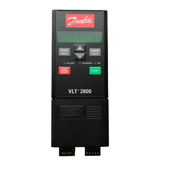
Page 29: Control Unit
See also [QUICK MENU] + [+]. [CHANGE DATA] is used for changing a setting. The [CHANGE DATA] key is also used for confirming a change of parameter settings. MG.27.E2.02 - VLT is a registered Danfoss trademark... -
Page 30: Hand Auto
Hand mode is activated: • Hand Start (LCP2) • Off Stop (LCP2) The display shows that in parameter 128 Motor thermal • Auto Start (LCP2) protection the selection made is Thermistor trip [2]. MG.27.E2.02 - VLT is a registered Danfoss trademark... -
Page 31: Automatic Motor Tuning
Automatic motor tuning Automatic motor tuning (AMT) is performed as follows: In parameter 107 Automatic motor tuning se- lect data value [2]. “107” will now flash, and “2” will not flash. MG.27.E2.02 - VLT is a registered Danfoss trademark... -
Page 32: The Lcp 2 Control Unit, Option
As a supplement to the display, there are three indicator lamps for voltage (ON), warning (WARNING) and alarm (ALARM). All MG.27.E2.02 - VLT is a registered Danfoss trademark... - Page 33 Extended status word [hex] If the local control keys are set to inactive, Analogue input 53 Analogue input 60 [mA] these will both become active when the frequency converter is set to Local con- MG.27.E2.02 - VLT is a registered Danfoss trademark...
- Page 34 In Menu mode, parameters will be split into groups, with the first digit (left) of the pa- rameter number indicating the group number of the parameter in question. MG.27.E2.02 - VLT is a registered Danfoss trademark...
-
Page 35: Parameter Selection
References & Limits Inputs & Outputs Special functions Serial communication Technical functions When the required parameter group has been selec- ted, each parameter can be chosen by means of the [+ / -] keys: MG.27.E2.02 - VLT is a registered Danfoss trademark... - Page 36 130 START FREQUENCY 10.0 HZ The chosen digit is indicated by the digit flashing. The bottom display line shows the data value that will be entered (saved) when signing off with [OK]. MG.27.E2.02 - VLT is a registered Danfoss trademark...
-
Page 37: Installation
VLT 2855-2875 380-480 Volt All dimensions are in mm. VLT 2803-2815 200-240 Volt VLT 2805-2815 380-480 Volt VLT 2822 200-240 Volt VLT 2822-2840 380-480 Volt VLT 2840 220-240 V, PD2 VLT 2880-82 380-480V MG.27.E2.02 - VLT is a registered Danfoss trademark... - Page 38 Motor coils (195N3110) Terminal cover The drawing below gives the dimensions for NEMA 1 terminal covers for VLT 2803-2875. Dimension 'a' depends on the unit type. RFI 1B filter (195N3103) IP 21 solution MG.27.E2.02 - VLT is a registered Danfoss trademark...
- Page 39 VLT 2822 200-240 V, VLT 2822-2840 380-480 V 195N2119 VLT 2840 200-240 V, VLT 2822 PD2, TR1 2855-2875 195N2120 380-480 V TR1 2880-2882 380-480 V, VLT 2840 PD2 195N2126 EMC filter for long motor cables 192H4719 192H4720 MG.27.E2.02 - VLT is a registered Danfoss trademark...
- Page 40 192H4893 MG.27.E2.02 - VLT is a registered Danfoss trademark...
-
Page 41: Mechanical Installation
Mechanical installation Side-by-side All VLT 2800 units can be installed side-by-side and in Please pay attention to the requirements any position, as the units do not require ventilation on that apply to installation. the side. The frequency converter is cooled by means of air cir- culation. -
Page 42: General Information About Electrical Installation
As a rule a distance of 20 cm is sufficient, but it is recommended that the distance is as great as pos- sible, particularly when cables are installed in parallel over large distances. MG.27.E2.02 - VLT is a registered Danfoss trademark... -
Page 43: Emc-Correct Electrical Installation
The illustration below shows EMC-correct electrical in- at high frequencies. Use cable clamps in- stallation, in which the frequency converter has been stead. fitted in an installation cabinet and connected to a PLC. MG.27.E2.02 - VLT is a registered Danfoss trademark... - Page 44 Z ommended. is rarely stated by cable manufacturers, but it is of- ten possible to estimate Z by looking at and assess- ing the physical design of the cable. MG.27.E2.02 - VLT is a registered Danfoss trademark...
-
Page 45: Earthing Of Screened/Armoured Control Cables
This problem is resolved by attaching one end of the screen to the earth via a 100 nF capacitor (short pin length). MG.27.E2.02 - VLT is a registered Danfoss trademark... -
Page 46: Diagram
Diagram * Integrated 1A RFI filter and brake is an option. ** VLT 2803-2815 200-240 V is not supplied with in- termediate circuit coils. MG.27.E2.02 - VLT is a registered Danfoss trademark... -
Page 47: Electrical Installation
Electrical installation See also the section Brake Connection. VLT 2822 200-240 V, 2822-2840 380-480 V VLT 2803-2815 200-240 V, 2805-2815 380-480 V MG.27.E2.02 - VLT is a registered Danfoss trademark... - Page 48 VLT 2840 200-240 V, VLT 2822 PD2, 2855-2875 380-480 V VLT 2880-2882 380-480 V, VLT 2840 PD2 Please note that the units will be supplied with two bottom plates; one for metric glands and one for con- duits. MG.27.E2.02 - VLT is a registered Danfoss trademark...
-
Page 49: Safety Clamp
In motors without phase insulation paper, verter, which can be seen from the name- an LC filter should be fitted on the output plate. of the frequency converter. MG.27.E2.02 - VLT is a registered Danfoss trademark... -
Page 50: Rfi Switch
Problems may arise at the start and at low rpm values if the motor sizes are widely different. This is because the small motors' relatively high ohmic resistance in MG.27.E2.02 - VLT is a registered Danfoss trademark... -
Page 51: Motor Cables
HF impedance. Motor thermal protection The electronic thermal relay in UL-approved frequency converters has received the UL-approval for single motor protection, when parameter 128 Motor thermal MG.27.E2.02 - VLT is a registered Danfoss trademark... -
Page 52: Load Sharing
139. If the frequency converter is placed at alarm status or in an overvoltage situation the mechanical brake is cut in immediately. MG.27.E2.02 - VLT is a registered Danfoss trademark... -
Page 53: Electrical Installation, Control Cables
100 nF capacitor between the screen and the chassis. Control cables must be screened/armoured. The screen must be connected to the frequency converter MG.27.E2.02 - VLT is a registered Danfoss trademark... -
Page 54: Tightening Torques, Control Cables
1 - 2 make (normally open) plug on the control card. Ordering number: 175N0131. 01 - 03 1 - 3 break (normally closed) LCP control unit with ordering number 175Z0401 is not to be connected. MG.27.E2.02 - VLT is a registered Danfoss trademark... -
Page 55: Connection Examples
Par. 305 Digital input = Jog [13] Par. 314 Analog input = Feedback [2] Par. 315 Terminal 60, min. scaling = 4 mA Par. 316 Terminal 60, max. scaling = 20 mA MG.27.E2.02 - VLT is a registered Danfoss trademark... - Page 56 Par. 217 Preset reference 3 = 25.00% Par. 218 Preset reference 4 = 35.00% Par. 100 Configuration = Speed regulation open loop [0] Par. 200 Output frequency range = Both di- rections, 0-132 Hz [1] MG.27.E2.02 - VLT is a registered Danfoss trademark...
-
Page 57: Use Of Internal Pid-Controller - Closed Loop Process Control
Main Menu (to enter the Main Menu: has managed to stop the VLT frequency converter. Press Quick Menu and + simultaneously). Set the following parameters: 100 = Process controller closed loop [3] MG.27.E2.02 - VLT is a registered Danfoss trademark... - Page 58 With the above connections and settings all normal pump and fan applications will work properly. In certain cases it might be neces- sary to optimize the PID-controllerr (parame- ter 440, 441 and 442) beyond the mentioned experienced values. MG.27.E2.02 - VLT is a registered Danfoss trademark...
-
Page 59: Programming
004 Active Setup. When an LCP 2 control unit is con- nected, the active Setup number will be appear in the = factory setting, () = display text, [] = value for use in communication via serial communication port MG.27.E2.02 - VLT is a registered Danfoss trademark... - Page 60 Setups. Shifts between Setups can be made = factory setting, () = display text, [] = value for use in communication via serial communication port MG.27.E2.02 - VLT is a registered Danfoss trademark...
- Page 61 Select Upload all parameters [1] if you want all param- eter values to be transferred to the control panel. Se- = factory setting, () = display text, [] = value for use in communication via serial communication port MG.27.E2.02 - VLT is a registered Danfoss trademark...
- Page 62 Pulse reference [Hz] gives the reference in Hz connec- 010-012 Small display readout. ted to terminal 33. = factory setting, () = display text, [] = value for use in communication via serial communication port MG.27.E2.02 - VLT is a registered Danfoss trademark...
- Page 63 [DISPLAY STA- parameter 002 Local/remote operation, Local opera- TUS] key. tion [1] has been chosen. = factory setting, () = display text, [] = value for use in communication via serial communication port MG.27.E2.02 - VLT is a registered Danfoss trademark...
- Page 64 Local operation [1] and parameter 013 Localcon- reference will be replaced by the remote-operated ref- erence signal. = factory setting, () = display text, [] = value for use in communication via serial communication port MG.27.E2.02 - VLT is a registered Danfoss trademark...
- Page 65 Pa- rameter 009-012 Display readout can be changed via the control panel. = factory setting, () = display text, [] = value for use in communication via serial communication port MG.27.E2.02 - VLT is a registered Danfoss trademark...
- Page 66 Quick Menu setup (quick menu setup) Value: [Index 1 - 20] Value: 0 - 999 = factory setting, () = display text, [] = value for use in communication via serial communication port MG.27.E2.02 - VLT is a registered Danfoss trademark...
-
Page 67: Load And Motor
Instance 20/70 or 21/71 is chosen in parameter 904 Instance types. = factory setting, () = display text, [] = value for use in communication via serial communication port MG.27.E2.02 - VLT is a registered Danfoss trademark... - Page 68 Y or delta ∆. Select a value that corresponds to the nameplate data on the motor. = factory setting, () = display text, [] = value for use in communication via serial communication port MG.27.E2.02 - VLT is a registered Danfoss trademark...
- Page 69 Description of choice: cedure by giving a STOP signal. can be set as follows: = factory setting, () = display text, [] = value for use in communication via serial communication port MG.27.E2.02 - VLT is a registered Danfoss trademark...
- Page 70 50% reduction of U/F ratio. Default value is OFF - 100% [OFF - 100] OFF. OFF % [OFF] = factory setting, () = display text, [] = value for use in communication via serial communication port MG.27.E2.02 - VLT is a registered Danfoss trademark...
- Page 71 Coasting (COAST) start delay time (parameter 120 Start delay time). DC hold (DC HOLD) = factory setting, () = display text, [] = value for use in communication via serial communication port MG.27.E2.02 - VLT is a registered Danfoss trademark...
-
Page 72: Dc Braking
DC braking becomes ETR warning 2 (ETR WARNING 2) = factory setting, () = display text, [] = value for use in communication via serial communication port MG.27.E2.02 - VLT is a registered Danfoss trademark... - Page 73 ETR Trip 1-4 if you want a trip when the motor is over- loaded according to the calculations. = factory setting, () = display text, [] = value for use in communication via serial communication port MG.27.E2.02 - VLT is a registered Danfoss trademark...
- Page 74 = factory setting, () = display text, [] = value for use in communication via serial communication port MG.27.E2.02 - VLT is a registered Danfoss trademark...
- Page 75 102-106. = factory setting, () = display text, [] = value for use in communication via serial communication port MG.27.E2.02 - VLT is a registered Danfoss trademark...
- Page 76 If 1.0 is selected, this corresponds to the AC brake being inactive. = factory setting, () = display text, [] = value for use in communication via serial communication port MG.27.E2.02 - VLT is a registered Danfoss trademark...
-
Page 77: References & Limits
Output frequency low limit, f (MIN OUTPUT FREQ) Value: 0.0 - f 0.0 Hz = factory setting, () = display text, [] = value for use in communication via serial communication port MG.27.E2.02 - VLT is a registered Danfoss trademark... - Page 78 External reference, % [25] in parameters 009-012 Dis- parameter 100 Configuration. play readout if a readout is desired. = factory setting, () = display text, [] = value for use in communication via serial communication port MG.27.E2.02 - VLT is a registered Danfoss trademark...
- Page 79 The minimum reference is preset if the motor has to run at a minimum speed, regardless of whether the resulting reference is 0. = factory setting, () = display text, [] = value for use in communication via serial communication port MG.27.E2.02 - VLT is a registered Danfoss trademark...
- Page 80 Description of choice: Set the required ramp-down time. = factory setting, () = display text, [] = value for use in communication via serial communication port MG.27.E2.02 - VLT is a registered Danfoss trademark...
-
Page 81: Reference Function
The formula for the calculation of the resulting reference can be seen in the section entitled All about the VLT 2800. See also the drawing in Handling of ref- erences. = factory setting, () = display text, [] = value for use in communication via serial communication port... - Page 82 215-218 Preset reference. converter can only handle a load intermittently, i.e. for = factory setting, () = display text, [] = value for use in communication via serial communication port MG.27.E2.02 - VLT is a registered Danfoss trademark...
- Page 83 46 and frequency has reached the resulting reference. The via the relay output. = factory setting, () = display text, [] = value for use in communication via serial communication port MG.27.E2.02 - VLT is a registered Danfoss trademark...
- Page 84 46 and via the relay output. The unit for feedback in Closed loop is programmed in parameter 416 Proc- ess units. = factory setting, () = display text, [] = value for use in communication via serial communication port MG.27.E2.02 - VLT is a registered Danfoss trademark...
-
Page 85: Inputs And Outputs
(terminals 18-33). converter "let go" of the motor immediately (output = factory setting, () = display text, [] = value for use in communication via serial communication port MG.27.E2.02 - VLT is a registered Danfoss trademark... - Page 86 Is not active at Process regulation, closed loop . See also parameter 200 Output frequency range/di- rection. = factory setting, () = display text, [] = value for use in communication via serial communication port MG.27.E2.02 - VLT is a registered Danfoss trademark...
- Page 87 Reset and start can be used as a start function. If 24 V are connected to the digital input, this will cause the = factory setting, () = display text, [] = value for use in communication via serial communication port MG.27.E2.02 - VLT is a registered Danfoss trademark...
- Page 88 Reference [1]. If this function is selected, the reference can be changed by means of an analogue reference = factory setting, () = display text, [] = value for use in communication via serial communication port MG.27.E2.02 - VLT is a registered Danfoss trademark...
- Page 89 [5] Time out (LIVE ZERO TIME O) Value: 1 - 99 sec. 10 sec. = factory setting, () = display text, [] = value for use in communication via serial communication port MG.27.E2.02 - VLT is a registered Danfoss trademark...
- Page 90 Output current higher than I par. 223 0-20 mA/ 4-20 mA. (above current low) [13] = factory setting, () = display text, [] = value for use in communication via serial communication port MG.27.E2.02 - VLT is a registered Danfoss trademark...
- Page 91 (see section about control of mechanical brake in the Design Guide). = factory setting, () = display text, [] = value for use in communication via serial communication port MG.27.E2.02 - VLT is a registered Danfoss trademark...
- Page 92 Is active if the frequency is lower than 0.1 Hz. Pulse current (PULSE CURRENT) [28] = factory setting, () = display text, [] = value for use in communication via serial communication port MG.27.E2.02 - VLT is a registered Danfoss trademark...
- Page 93 33. In this way an internal stop signal will activate the normal ramp down time (parameter 208). = factory setting, () = display text, [] = value for use in communication via serial communication port MG.27.E2.02 - VLT is a registered Danfoss trademark...
- Page 94 The factory setting is 10 ms. This means that it is as- sumed that the total delay from the Sensor, PLC and other hardware corresponds to this setting. Only active for speed-compensated stop. MG.27.E2.02 - VLT is a registered Danfoss trademark...
-
Page 95: Special Functions
(RESET AT POWER UP) [11] application, like the ETR will protect the motor if se- lected. = factory setting, () = display text, [] = value for use in communication via serial communication port MG.27.E2.02 - VLT is a registered Danfoss trademark... - Page 96 Set the value to be shown on the display as the mini- mum feedback signal value on the selected feedback input (parameters 308/314 Analogue inputs). = factory setting, () = display text, [] = value for use in communication via serial communication port MG.27.E2.02 - VLT is a registered Danfoss trademark...
- Page 97 Pulses/s (PULSE/S) nal. Units/s (UNITS/S) Units/min. (UNITS/MI) VLT 2800 Regulators Units/h (Units/h) The VLT 2800 has two integrated PID regulators, one °C (°C) [10] to regulate speed and one to regulate processes. Pa (pa) [11] Speed regulation and process regulation require a...
-
Page 98: Pid Functions
= factory setting, () = display text, [] = value for use in communication via serial communication port MG.27.E2.02 - VLT is a registered Danfoss trademark... -
Page 99: Handling Of Feedback
437 PID normal/inverted control must be between voltage, current and pulse feedback signals. programmed at Inverted . = factory setting, () = display text, [] = value for use in communication via serial communication port MG.27.E2.02 - VLT is a registered Danfoss trademark... - Page 100 The differentiator does not react to a constant error. It only makes a contribution when the error changes. = factory setting, () = display text, [] = value for use in communication via serial communication port MG.27.E2.02 - VLT is a registered Danfoss trademark...
- Page 101 Set the output frequency (F2) that is to match the sec- ond output voltage (U2), parameter 425 U2 voltage . = factory setting, () = display text, [] = value for use in communication via serial communication port MG.27.E2.02 - VLT is a registered Danfoss trademark...
- Page 102 Normal [0].If the frequency converter is to increase the output frequency in case the feedback signal increa- ses, select Inverse [1]. = factory setting, () = display text, [] = value for use in communication via serial communication port MG.27.E2.02 - VLT is a registered Danfoss trademark...
- Page 103 1.6 Hz. If the feedback signal = factory setting, () = display text, [] = value for use in communication via serial communication port MG.27.E2.02 - VLT is a registered Danfoss trademark...
- Page 104 Use the DC brake instead. = factory setting, () = display text, [] = value for use in communication via serial communication port MG.27.E2.02 - VLT is a registered Danfoss trademark...
- Page 105 This is used, e.g. where regulation of a flow (volume) is required on the basis of pressure as = factory setting, () = display text, [] = value for use in communication via serial communication port MG.27.E2.02 - VLT is a registered Danfoss trademark...
-
Page 106: Enhanced Sleep Mode
Sleep-mode or trips case of dry run. This is assured by the Dry run detec- due to dry run, depending on the configuration. tion feature. MG.27.E2.02 - VLT is a registered Danfoss trademark... - Page 107 = factory setting, () = display text, [] = value for use in communication via serial communication port MG.27.E2.02 - VLT is a registered Danfoss trademark...
- Page 108 202 Output frequency high over the whole frequency range. limit, f = factory setting, () = display text, [] = value for use in communication via serial communication port MG.27.E2.02 - VLT is a registered Danfoss trademark...
- Page 109 10 times within 100 seconds. If parameter 471 is set to 30 min. the fre- • The VLT 2800 drive is in Closed Loop mode quency converter will consequently not be able to (parameter 100).
- Page 110 Value: step. Param. 414 - Param. 205 - Param. 414 Operate the VLT 2800 in HAND mode and Function: slowly advance the speed to fill the pipe while The value set in this parameter corresponds to the being careful not to create a water hammer.
-
Page 111: Serial Communication For Vlt 2800
• Profidrive protocol control byte (BCC). • Danfoss FC protocol To select Danfoss FC protocol, parameter 512 Tele- gram Profile is set to FC protocol [1]. Telegram timing Telegram Traffic The communication speed between a master and a Control and response telegrams slave depends on the baud rate. - Page 112 Bit 0-6 = 0 Broadcast The slave sends the address byte back unchanged in the response telegram to the master. Example: writing to frequency converter address 22 (16H) with address format 1-31: MG.27.E2.02 - VLT is a registered Danfoss trademark...
- Page 113 Data change is not possible because factory Setup is selected Bits no. 12-15 are used to transfer parameter com- mands from master to slave and the slave's processed responses back to the master. MG.27.E2.02 - VLT is a registered Danfoss trademark...
- Page 114 100 Hz, see conversion. 621 - 635 Nameplate data is data type 9. For example, in parameter 621 Unit type it is possible to read the unit size and mains voltage range. MG.27.E2.02 - VLT is a registered Danfoss trademark...
-
Page 115: Control Word According To Fc Protocol
(e.g. a PC) to a slave (frequency converter). If the val- ue in parameter 207 Ramp-up time 1 is 10 sec., the response from the slave to the master will be: MG.27.E2.02 - VLT is a registered Danfoss trademark... - Page 116 Bit 03 gates with the because the control word is always contained in the corresponding function on a digital input. telegram, regardless of which type of telegram is used, MG.27.E2.02 - VLT is a registered Danfoss trademark...
-
Page 117: Status Word According To Fc Profile
Bit 04, Not used: Bit 04 is not used in the status word. Bit 05, Not used: Bit 05 is not used in the status word. MG.27.E2.02 - VLT is a registered Danfoss trademark... -
Page 118: Control Word According To Fieldbus Profile
221 Current LimitI and that the frequency converter will trip after a set period of time. Bit 15, Thermal warning: Bit 15 = '0' means that there is no thermal warning. MG.27.E2.02 - VLT is a registered Danfoss trademark... -
Page 119: Status Word According To Profidrive Protocol
Bit 05, ON 3/OFF 3: protocol. Bit 05 = '0' means that Bit 02 in the control word = '1'. Bit 05 = '1' means that Bit 02 in the control word = '0'. MG.27.E2.02 - VLT is a registered Danfoss trademark... - Page 120 It is possible to change the direction of rotation via the serial reference. This is done by converting the binary reference value to 2' complement. See example. Example - Control word and serial communication ref.: MG.27.E2.02 - VLT is a registered Danfoss trademark...
- Page 121 Par. 201 Output frequency low limit = 0 Hz Par. 202 Output frequency high limit = 50 Hz Status word = 0F03 Hex. Output frequency = 2000 Hex • 50% of the frequency range, corresponding to 25 Hz. MG.27.E2.02 - VLT is a registered Danfoss trademark...
-
Page 122: Serial Communication
Parameter 501 Baudrate cannot be selected via the Coasting Motor running serial port, but must be preset via the operating unit. = factory setting, () = display text, [] = value for use in communication via serial communication port MG.27.E2.02 - VLT is a registered Danfoss trademark... - Page 123 The table below shows when the motor has stopped and when the frequency converter has a start com- = factory setting, () = display text, [] = value for use in communication via serial communication port MG.27.E2.02 - VLT is a registered Danfoss trademark...
- Page 124 Anti-clockwise Anti-clockwise Serial port [1] Dig. input Ser. port Function Clockwise Anti-clockwise Clockwise Anti-clockwise = factory setting, () = display text, [] = value for use in communication via serial communication port MG.27.E2.02 - VLT is a registered Danfoss trademark...
- Page 125 It is possible to choose between two different control word profiles. Description of choice: Select the desired control word profile. Selection of preset ref. See Serial port for VLT 2800 for further details of control (PRES.REF. SELECT) word profiles. Value: Digital input (DIGITAL INPUT)
- Page 126 LCP display. See also param- via an LCP control unit. eters 009-012 Display readout. = factory setting, () = display text, [] = value for use in communication via serial communication port MG.27.E2.02 - VLT is a registered Danfoss trademark...
- Page 127 27, 29 and 33). Input 18 corresponds to the bit on the started. extreme left. '0' = no signal, '1' = connected signal. = factory setting, () = display text, [] = value for use in communication via serial communication port MG.27.E2.02 - VLT is a registered Danfoss trademark...
- Page 128 Modbus parity and message framing (M.BUS PAR./FRAME) Value: (EVEN/1 STOPBIT) (ODD/1 STOPBIT) = factory setting, () = display text, [] = value for use in communication via serial communication port MG.27.E2.02 - VLT is a registered Danfoss trademark...
- Page 129 Function: The three parameters hold a list of all the parameters that are defined in the VLT 2800. It is possible to read single elements of the list by using the corresponding subindex. The subindexes start at 1 and follow the or- der of the parameter numbers.
-
Page 130: Technical Functions
Read out as one value. Parameters 615-617 Fault log cannot be read out via the integral control unit. = factory setting, () = display text, [] = value for use in communication via serial communication port MG.27.E2.02 - VLT is a registered Danfoss trademark... - Page 131 601 is reset to zero Hours run. This parameter cannot be selected via se- rial communication. = factory setting, () = display text, [] = value for use in communication via serial communication port MG.27.E2.02 - VLT is a registered Danfoss trademark...
- Page 132 Setups, with the exception of pa- rameters 500 Address, 501 Baudrate, 600-605 Operating data and 615-617 Fault log. = factory setting, () = display text, [] = value for use in communication via serial communication port MG.27.E2.02 - VLT is a registered Danfoss trademark...
- Page 133 Example: 1.15 The ID number of the unit's power section appears here. Parameter 700 - Example: ID 1.15. Only for wobble functions: To use this function or for further information, please see MI29J2xx. MG.27.E2.02 - VLT is a registered Danfoss trademark...
-
Page 134: All About Vlt 2800
In order to maintain PELV all connections made to the overcurrent in the IGBT module, which means that all control terminals must be PELV, e.g. thermistor must transistors in the IGBT module would independently be reinforced/double insulated. cut out. MG.27.E2.02 - VLT is a registered Danfoss trademark... -
Page 135: Du/Dt On Motor
) is the maximum AMB,MAX temperature allowed. The average (T ) meas- AMB,AVG ured over 24 hours, must be at least 5 °C lower. If the frequency converter operates at temperatures above MG.27.E2.02 - VLT is a registered Danfoss trademark... -
Page 136: Temperature-Dependent Switch Frequency
) must be derated in accordance electronics of the frequency converter. with the diagram below: VLT 2800 has a pulse pattern in which it is possible to set the switching frequency from 3.0- 10.0/14.0 kHz. MG.27.E2.02 - VLT is a registered Danfoss trademark... -
Page 137: Vibration And Shock
In general, the switching frequency does not affect the UL Standard efficiency of small motors. This device is UL-approved. MG.27.E2.02 - VLT is a registered Danfoss trademark... -
Page 138: Mains Supply Interference/Harmonics
The lower the power factor, the higher the I for the same kW performance. In addition, a high power factor indicates that the different harmonic currents are low. MG.27.E2.02 - VLT is a registered Danfoss trademark... -
Page 139: Generic Emc Standards/Product Standards
EN 55011: EmissionLimits and methods of measurement of radio disturbance characteristics of indus- trial, scientific and medical (ISM) high-frequency equipment. Class 1A: Equipment used in an industrial environment. Class 1B: Equipment used in areas with a public supply network (residential, commerce and light industry). MG.27.E2.02 - VLT is a registered Danfoss trademark... -
Page 140: Emc Immunity
• EN 61000-4-6 (IEC 61000-4-6): RF Common mode Simulation of the effect from radio-transmitting equipment connected to connection cables. See following EMC immunity form. MG.27.E2.02 - VLT is a registered Danfoss trademark... -
Page 141: Harmonic Current Emission
In very dusty areas, cabinet verter, there is a risk of stoppages, which MG.27.E2.02 - VLT is a registered Danfoss trademark... - Page 142 Indicators that there are aggressive gases in the air are copper rails and cable ends that are black on existing electrical installations. MG.27.E2.02 - VLT is a registered Danfoss trademark...
-
Page 143: Display Readout
The frequency converter shows the present Hand mode reference frequency in Herz (Hz). The frequency converter shows scaled output fre- quency (the present output frequency x parameter 008). MG.27.E2.02 - VLT is a registered Danfoss trademark... - Page 144 5 - 10 sec. Note: pends on the device, and is set at 5 - 10 sec. An The frequency converter will trip with an alarm 7 (over- MG.27.E2.02 - VLT is a registered Danfoss trademark...
- Page 145 221 Current Limit , and the frequency converter but there will not be a warning in the display. will trip after a set time, selected in parameter 409 Trip delay overcurrent. MG.27.E2.02 - VLT is a registered Danfoss trademark...
- Page 146 There is inconsistency between the registered motor data. Check the motor data for the relevant setup. ALARM 37-45: Internal fault If one of these failures occurs, please contact Danfoss. ALARM 52: AMT missing motor phase The AMT function has detected a missing motor Alarm 37, internal fault number 0: Communication fault phase.
-
Page 147: Warning Words, Extended Status Words And Alarmwords
Slow down 000010 Catch-up 000020 Feedback high 000040 Feedback low 000080 Output current high 000100 Output current low 000200 Output frequency high 000400 Output frequency low 002000 Braking 008000 Out of frequency range MG.27.E2.02 - VLT is a registered Danfoss trademark... -
Page 148: General Technical Data
(terminals 18, 19, 27, 29) approx. 4 kΩ Input resistance, R (terminal 33) approx. 2 kΩ All digital inputs are galvanically isolated from the supply voltage (PELV) and other high-voltage terminals. See section entitled Galvanic Isolation. MG.27.E2.02 - VLT is a registered Danfoss trademark... - Page 149 Max. error: 0.2 % of full scale Resolution on frequency output 10 bit The digital output is galvanically isolated from the supply voltage (PELV) and other high-voltage terminals. See section entitled Galvanic Isolation. MG.27.E2.02 - VLT is a registered Danfoss trademark...
- Page 150 Terminal number 70 Common for terminals 67, 68 and 69 Full galvanic isolation. See section entitled Galvanic Isolation. For CANopen/DeviceNet units, see VLT 2800 DeviceNet manual, MG.90.BX.YY. Relay outputs: Number of programmable relay outputs Terminal number, control card (resisitvie and inductive load) 1-3 (break), 1-2 (make) Max.
- Page 151 EN 61081-2, EN 61800-3, EN 55011 EN 50082-1/2, EN 61000-4-2, EN 61000-4-3, EN 61000-4-4, EN 61000-4-5, EN EMC standards, Immunity 61000-4-6, EN 61800-3 See section on special conditions in the Design Guide MG.27.E2.02 - VLT is a registered Danfoss trademark...
- Page 152 • The frequency converter is protected against earth fault on motor terminals U, V, W. MG.27.E2.02 - VLT is a registered Danfoss trademark...
-
Page 153: Technical Data, Mains Supply 1 X 220 - 240 V/3 X 200-240V
100,000 amps RMS (symmetrical), 500 V maximum. 3. Measured using a 25 m screened/armoured motor cable with a rated load and rated frequency. 4. IP20 is standard for VLT 2805-2875, whereas NEMA 1 is an option. MG.27.E2.02 - VLT is a registered Danfoss trademark... -
Page 154: Technical Data, Mains Supply 3 X 380 - 480 V
100,000 amps RMS (symmetrical), 500 V maximum. 3. Measured using a 25 m screened/armoured motor cable with a rated load and rated frequency. 4. IP20 is standard for VLT 2805-2875, whereas NEMA 1 is an option. MG.27.E2.02 - VLT is a registered Danfoss trademark... -
Page 155: Available Literature
Available literature Supplied with the unit Below is a list of the literature available for VLT 2800. It must be noted that there may be deviations from one country to the next. Supplied with the unit: Operating instructions MG.28.AX.YY Various literature for VLT 2800: Design Guide MG.28.EX.YY... - Page 156 This number refers to a conversion figure to be used Unsigned 32 when writing or reading via serial communication with Text string a frequency converter. See Data character in Serial communication in the Design Guide. MG.27.E2.02 - VLT is a registered Danfoss trademark...
- Page 157 Brake cut out value 3.0 Hz Brake cut in frequency 3.0 Hz Current, minimum value Leak reactance depends on motor selected Internal ventilator control Automatic AC brake factor 1.30 Reset voltage vector MG.27.E2.02 - VLT is a registered Danfoss trademark...
- Page 158 Warn. Low frequency 0.0 Hz Warn. High frequency 132.0 Hz Warn. Low Feedback -4000.000 Warn. High Feedback 4000.000 Frequency bypass, 0 Hz (OFF) bandwidth Frequency bypass 1 0.0 Hz Frequency bypass 2 0.0 Hz MG.27.E2.02 - VLT is a registered Danfoss trademark...
- Page 159 This number refers to a conversion figure to be used Unsigned 32 when writing or reading via serial communication with Text string a frequency converter. See Data character in Serial communication in the Design Guide. MG.27.E2.02 - VLT is a registered Danfoss trademark...
- Page 160 Off (0.00 s). Proc. PID diff. ampl. limit Proc. PID lowpass filter time 0.02 s Flying start Not possible Speed PID feedforward factor 100% Controller range 10 % Brake voltage reduce Feedback conversion Linear MG.27.E2.02 - VLT is a registered Danfoss trademark...
- Page 161 Data readout: Status word Data readout: Bus feedback 1 Data readout: Inverter temperature Data readout: Alarm word Data readout: Control word Data readout: Warning word Data readout: Extended status word Data readout: Pulse count MG.27.E2.02 - VLT is a registered Danfoss trademark...
- Page 162 This number refers to a conversion figure to be used Unsigned 32 when writing or reading via serial communication with Text string a frequency converter. See Data character in Serial communication in the Design Guide. MG.27.E2.02 - VLT is a registered Danfoss trademark...
-
Page 163: Index
Display mode Catch up Display mode CE labelling Display readout CHANGE DATA Display readout Connection of a 2-wire transmitter Display scaling of output frequency Connection of mechanical brake DU/dt on motor Constant torque MG.27.E2.02 - VLT is a registered Danfoss trademark... - Page 164 Galvanic Isolation (PELV) Mechanical brake Mechanical installation Hand Auto Menu mode Hand operation Menu mode Handling of references Motor cables Harmonics Motor coils High voltage test Motor coils High voltage warning Motor connection MG.27.E2.02 - VLT is a registered Danfoss trademark...
- Page 165 Ramp type Operating Data Ramp-down time Operating mode at power-up, local operation Ramp-up time Order form Rated motor speed Ordering numbers for VLT 2800 200-240 V Ordering numbers for VLT 2800 380-480V RCD relays Output frequency Reference Overmodulation function Reference function...
- Page 166 Telegram Traffic Temperature-dependent switch frequency Terminal 42 Terminal 46 Terminal 53 Terminal 60 Terminal cover Terminals The differentiator Thermal motor protection Thermistor Thermistor Tightening Torque, Power Terminals Time out Torque characteristic U/f-ratio MG.27.E2.02 - VLT is a registered Danfoss trademark...
Need help?
Do you have a question about the VLT 2800 and is the answer not in the manual?
Questions and answers