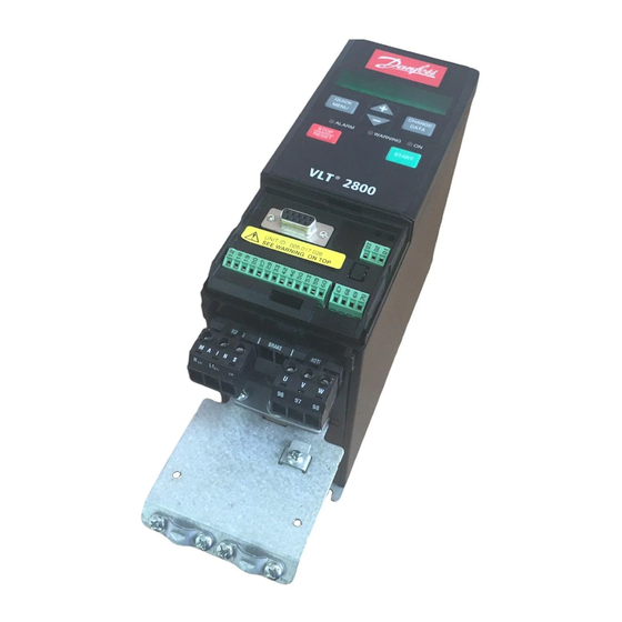
Danfoss FCM 300 Operating Instructions Manual

Danfoss FCM 300 Operating Instructions Manual

Induction motor
Hide thumbs Also See for FCM 300:

Advertisement

Operating Instructions
Profibus DP V1
FCM 300
FCD 300
®
VLT
2800

Advertisement

Table of Contents
loading

Summary of Contents for Danfoss FCM 300

  • Page 1 Operating Instructions Profibus DP V1 FCM 300 FCD 300 ® 2800...
  • Page 2: Table Of Contents

    ® FCM 300 / FCD 300 / VLT 2800 / DP V1 PROFIBUS Contents Introduction ....................... Quick Start ......................Profibus DP ......................Baudrate ........................ Profibus DP V1 ....................... System layout ....................Master-controlled frequency converters ..............Bus topology ......................Features of DP (Distributed Periphery) ..............
  • Page 3: Introduction

    This manual assumes that you are using a DANFOSS The symbols used are the following: FCM 300, FCD 300 or VLT 2800 with PROFIBUS. It is also assumed that you, as a master, are using a PLC or Indicates a general warning.
  • Page 4 ® FCM 300 / FCD 300 / VLT 2800 / DP V1 PROFIBUS The Profibus DP V1 replaces the former Profibus DP V0 functionality. Note: The 3MB and 12MB Profibus option are separate options and have different ordering numbers. What you should already know...
  • Page 5: Quick Start

    PPO is defined as a connected module. The frequency converter parameters may be gathered parameter interface (PCV, length of 8 bytes) of the from the Design Guide for the FCM 300, the PPO always has module consistency. FCD 300 and VLT 2800.
  • Page 6: System Layout

    ® FCM 300 / FCD 300 / VLT 2800 / DP V1 PROFIBUS Master-controlled frequency converters The PROFIBUS Fieldbus was designed to give you unprecedented flexibility and command over your controlled system. The PROFIBUS will perform as an integrated part of your frequency converter, giving you access to all parameters relevant to your application.
  • Page 7: Bus Topology

    ® FCM 300 / FCD 300 / VLT 2800 / DP V1 PROFIBUS Bus topology - Single master Single master operation with DP V0 - PLC communicates with telegrams of constant length - Fits to time critical requirements Cyclical transmission (PLC) 1.
  • Page 8: Profibus Dp V1

    ® FCM 300 / FCD 300 / VLT 2800 / DP V1 PROFIBUS Profibus DP V1 Features of a Master type 1 connection The Profibus DP extension DP V1 offers additional - Cyclical data exchange (DP V0). to the cyclical data communication an acyclical - Acyclical read/write on parameters.
  • Page 9 The minimum obtainable communication is the time it takes to transmit data from the master to time with the FCM 300/FCD 300/VLT 2800 with the slave (FCM 300/FCD 300/VLT 2800 with profibus), PROFIBUS is approx. 100 msec per slave, when...
  • Page 10: The Profibus Interface

    ® FCM 300 / FCD 300 / VLT 2800 / DP V1 PROFIBUS The Profibus Interface The total drop cable length for one segment is - Impedance: 135 to 165 ohm at a measuring limited as stated in the table below.
  • Page 11 ® FCM 300 / FCD 300 / VLT 2800 / DP V1 PROFIBUS Max. total bus cable length Transmission speed 1 segment: 2 segments: 3 segments: 4 segments: 32 nodes 64 nodes 96 nodes 128 nodes (31 VLT) (1 repeater, 61 VLT)
  • Page 12: Cable Connection Fcm 300

    PROFIBUS network. Additional information on EMC can be found in the design guide on the FCM 300 (MG.03.BX.02). Please also consult the manual of the PROFIBUS master for further installation guidelines.
  • Page 13 ® FCM 300 / FCD 300 / VLT 2800 / DP V1 PROFIBUS The bus termination - FCM 300 1 = RxD/TxD-P∼ (red cable) 2 = RxD/TxD-N∼ (green cable) It is essential that the bus line is terminated properly. A mismatch of impedance may result in reflections on the line that will corrupt data transmission.
  • Page 14 ® FCM 300 / FCD 300 / VLT 2800 / DP V1 PROFIBUS FCM 300 LEDs There are 2 LEDs on the PROFIBUS: LED303: Lights up when the card is initialized and ready to communicate. It will flash while auto baudrate detection is attempting to detect the actual baudrate.
  • Page 15: Cable Connection Fcd 300

    ® FCM 300 / FCD 300 / VLT 2800 / DP V1 PROFIBUS Physical connection FCD 300 Especially when having long distances between the The PROFIBUS is connected to the bus line stations in a PROFIBUS network it can be necessary to via, terminals 68 and 69.
  • Page 16 ® FCM 300 / FCD 300 / VLT 2800 / DP V1 PROFIBUS The bus termination 68 = RxD/TxD-P∼ (red cable) 69 = RxD/TxD-N∼ (green cable) It is essential that the bus line be terminated properly. - If an external termination circuit consisting of three A mismatch of impedance may result in reflections resistors is connected to the bus line a 5 V d.c.
  • Page 17 ® FCM 300 / FCD 300 / VLT 2800 / DP V1 PROFIBUS Switch Address Switch setting ..125 (default) FCD 300 LEDs The bus LED on the front: LCP stop mode or Remote and bus control Operation site = local...
  • Page 18: Cable Connection Vlt 2800

    ® FCM 300 / FCD 300 / VLT 2800 / DP V1 PROFIBUS Physical connection VLT 2800 a low HF (high frequency) impedance. This can The PROFIBUS is connected to the bus line be achieved by connecting a large surface area of via, terminals 68 and 69.
  • Page 19 ® FCM 300 / FCD 300 / VLT 2800 / DP V1 PROFIBUS The bus termination 68 = RxD/TxD-P∼ (red cable) 69 = RxD/TxD-N∼ (green cable) It is essential that the bus line be terminated properly. terminal block 67-70 (see drawing below). The A mismatch of impedance may result in reflections switches 1 and 2 should be on to terminate the bus.
  • Page 20 ® FCM 300 / FCD 300 / VLT 2800 / DP V1 PROFIBUS VLT 2800 LEDs There are 2 LEDs on the PROFIBUS: LD851: Lights up when the card is initialized and ready to communicate. It will flash while auto baudrate detection is attempting to detect the actual baudrate.
  • Page 21: Profibus Dp

    ® FCM 300 / FCD 300 / VLT 2800 / DP V1 PROFIBUS Profibus DP DP communication relations The selection of PPO type is made according Communication according to PROFIBUS DP, i.e. EN to the master configuration. 50170 part 3, is supported. Consequently a master that supports PROFIBUS DP must be used.
  • Page 22 ® FCM 300 / FCD 300 / VLT 2800 / DP V1 PROFIBUS Function PCA handling sponse The PCA portion of the PPO types 1, 2 and 5 No response will handle a number of tasks. The master may Transfer parameter value (word)
  • Page 23 ® FCM 300 / FCD 300 / VLT 2800 / DP V1 PROFIBUS Parameter and data type structure description Size attribute Parameter description The size index and the conversion index for each DP has a number of describing attributes (see rigth).
  • Page 24 Byte 2 Byte 3 Byte 4 300, FCD 300 and VLT 2800 0 ms ms 2 ms 2 Data types supported by FCM 300, FCD 300 and 0 ms ms 2 ms 2 VLT 2800 0 ms ms 2 ms 2...
  • Page 25 ® FCM 300 / FCD 300 / VLT 2800 / DP V1 PROFIBUS Synchronize and freeze SYNC/UNSYNC can be used to obtain simultaneous The control commands SYNC/UNSYNC and reactions in several slaves, for example synchronised FREEZE/UNFREEZE are broadcast functions. start, stop or speed change. A SYNC command...
  • Page 26 ® FCM 300 / FCD 300 / VLT 2800 / DP V1 PROFIBUS Clear Mode / Fail Safe For masters, that do not support Fails Safe Clear, If the PLC/Master functions are seriously disturbed, the the drive will have the same reaction on a clear DP master will go into Clear Mode.
  • Page 27 ® FCM 300 / FCD 300 / VLT 2800 / DP V1 PROFIBUS Control word/Status word Control word The bits of the "Control word" tell the frequency The control words are used to send control converter how to react, while the "Status word"...
  • Page 28 ® FCM 300 / FCD 300 / VLT 2800 / DP V1 PROFIBUS Status word When the frequency converter returns the frame to the master, the same two bytes operate as status from the frequency converter with the following functions: Status word According to PROFIDRIVE control word (par.
  • Page 29 ® FCM 300 / FCD 300 / VLT 2800 / DP V1 PROFIBUS Example PCD: Process Data This example shows how PPO type 1 is used PCV: Parameter-Characteristics-Value for changing the ramp-up time (parameter 207) PCA: Parameter-Characteristics (Bytes 1, 2)
  • Page 30 ® FCM 300 / FCD 300 / VLT 2800 / DP V1 PROFIBUS Byte Value The PCV part is a "hand shake" procedure which means that the frequency converter has to acknowledge the command, before a new one can be written.
  • Page 31: Dp V1 Identifications

    ® FCM 300 / FCD 300 / VLT 2800 / DP V1 PROFIBUS DP V1 Identifications can replace a V0 unit without changing the master The V1 functionalities require a GSD file supporting configuration. The table shows the available GSD V1.
  • Page 32: Parameters

    PROFIBUS option. We refer to the parameter description in the design guide on the FCM 300 Series (MG.03.Bx.02), the design guide on the FCD 300 (MG.04.Ax.02) and the design guide on the VLT 2800 Series (MG.28.EX.02).
  • Page 33 2800 / DP V1 PROFIBUS PROFIBUS specific parameters Select setup 2 is selected, the FCM 300/FCD 300 / VLT 2800 will remain in Setup 2 until parameter 4 is changed. 2. Parameter 804 = Off Þ control via PROFIBUS is 800 Protocol select resumed and the most recent control word is used.
  • Page 34 ® FCM 300 / FCD 300 / VLT 2800 / DP V1 PROFIBUS 825 Delayed speed change delay Function: This function allows to disable the commu- (SPEED CNG. DELAY) nication interface. Value: 20 - 10000 (20 ms-10 s) Description of choice:...
  • Page 35 ® FCM 300 / FCD 300 / VLT 2800 / DP V1 PROFIBUS 904 PPO type select for DP Function: Different parameters may be assigned to the PCD 3-10 (PPO TYPE SELECT) of the PPOs (the max.number of the PCD depends on Value: the PPO type).
  • Page 36 Function: Description of choice: The process control (adjustment of control word, speed - OFF: The FCM 300/FCD 300/VLT 2800 will not reference value and of the following variable PCD) can issue spontaneous messages or event notification be blocked. Control through the control card terminals in case of a warning or an alarm.
  • Page 37 ® FCM 300 / FCD 300 / VLT 2800 / DP V1 PROFIBUS is still possible via the terminals, depending on how Bit 7 = 0: Run time failure the parameters 502-508 have been programmed. Code 0 OK 1 Fatal error in warning channel...
  • Page 38 Setup 1 (SETUP 1) The three parameters hold a list of all the parameters Setup 2 (SETUP 2) that are defined in the FCM 300/FCD 300/VLT 2800. Setup 3 (SETUP 3) It is possible to read single elements of the list by DP Setup 4 (SETUP 4) by using the corresponding subindex.
  • Page 39 ® FCM 300 / FCD 300 / VLT 2800 / DP V1 PROFIBUS Read only parameters, as for example data read For parameter store, the following should be observed: out parameters, will not be registered as modified A Write command to a frequency converter parameter eventhough they are changing.
  • Page 40: Warnings And Alarm Messages

    Warning word, extended Status word and There is a clear distinction between alarms and Alarm word warnings. In the case of an alarm, the FCM 300/FCD Warning word, extened status word and alarm word 300/VLT 2800 will enter a fault condition. After the are shown on the display in Hex format.
  • Page 41 ® FCM 300 / FCD 300 / VLT 2800 / DP V1 PROFIBUS Unit Alarm word (p. 541) (Hex) diagnose 00000001 Ramping 00000002 Automatic motor tuning 00000004 Start clockwise/anti- clockwise 00000008 Slow down 00000010 Catch-up 00000020 Feedback high 00000040 Feedback low...
  • Page 42: Station Address

    ® FCM 300 / FCD 300 / VLT 2800 / DP V1 PROFIBUS Station address frequency converter. The setting of parameter 849 The station address of slave can be selected via determines which frequency converter events should trigger the extended diagnose function.
  • Page 43: Glossary

    ® FCM 300 / FCD 300 / VLT 2800 / DP V1 PROFIBUS Abbreviations English German Elaboration Acyclical Control Interval Application Layer Interface ATTR Attribute BRCT Broadcast Cyclical Control Interval Communication Reference Communication Reference List CSRD Cyclical Send and Request Data...
  • Page 44: Parameter List

    ® FCM 300 / FCD 300 / VLT 2800 / DP V1 PROFIBUS Parameter list with factory settings Parameter Factory setting 4-setup Conv. Data description index type Language English Local/remote operation Remote-controlled Local reference 000,000.000 Active Setup Setup 1 Programming Setup...
  • Page 45 ® FCM 300 / FCD 300 / VLT 2800 / DP V1 PROFIBUS Parameter- Factory setting 4-setup Conv. Data- description index type Configuration Speed reg., open loop Torque characteristics Constant torque Motor power P depends on unit Motor voltage U...
  • Page 46 ® FCM 300 / FCD 300 / VLT 2800 / DP V1 PROFIBUS Parameter Factory setting 4-setup Conv. Data description index type Output frequency range Clockwise only, 0-132 Hz Output frequency, 0.0 Hz low limit f Output frequency, 132 Hz...
  • Page 47 ® FCM 300 / FCD 300 / VLT 2800 / DP V1 PROFIBUS Parameter Factory setting 4-setup Conv. Data description index type Digital input, term. 18 Start Digital input, term. 19 Reversing Digital input, term. 27 Reset and coast inverse Digital input, term.
  • Page 48 ® FCM 300 / FCD 300 / VLT 2800 / DP V1 PROFIBUS Parameter Factory setting 4-setup Conv. Data description index type Brake function Depends on unit type Reset function Manual reset Aut. restart time 5 sec. Trip delay overcurrent Off (61 sec.)
  • Page 49 ® FCM 300 / FCD 300 / VLT 2800 / DP V1 PROFIBUS Parameter Factory setting 4-setup Conv. Data description index type Address Baudrate 9600 Baud Coasting stop Logic or Quick stop Logic or DC brake Logic or Start Logic or...
  • Page 50 ® FCM 300 / FCD 300 / VLT 2800 / DP V1 PROFIBUS Parameter Factory setting 4-setup Conv. Data description index type Operating hours Hours run kWh counter Number of cut ins Number of overtemperatures Number of overvoltages Fault log: Error code...
  • Page 51: Index

    ® FCM 300 / FCD 300 / VLT 2800 / DP V1 PROFIBUS Index ................LEDs .................... Abbreviations Master-controlled frequency converters ....................... About this manual Modified parameters ......... Active spontaneous messages ................ Alarms ..............Assumptions ............number of nodes ............
  • Page 52 ® FCM 300 / FCD 300 / VLT 2800 / DP V1 PROFIBUS ..........Synchronize and freeze ..............Update time ............VLT 2800 LEDs .......... Warning and alarm messages ............. Warning parameter 1 ..............Warnings ........What you should already know...
  • Page 53 XREF__BC NOT LOADED ON RIP www.danfoss.com/drives 175R0197 MG90A502 *MG90A502* Rev. 2003-09-01...

This manual is also suitable for:

Fcd 300Vlt 2800Dp v1 profibus

Table of Contents