Table of Contents
Advertisement
Device manual
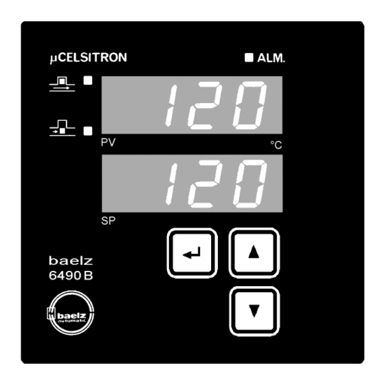
Microprocessor-based controller µCelsitron baelz 6490B,
baelz 6490B-y and baelz 6590B
Universal three-position step controller
Industrial controller with special PID step controller algorithm
Compact design 96mm x 96mm x 135mm
Easy operation
User-defined operating level
Digital displays for process variable and
setpoint
Indication of the manipulated variable
(at 6490B-y with additional bargraph display)
Control structure PI and PID
Two-position control
Three-position control
Setpoint ramp
Technical data subject to change without notice
W. Bälz & Sohn GmbH & Co.
Koepffstraße 5
D-74076 Heilbronn
6490B / 6490B-y / 6590B
Compact design 48mm x 96mm x 140mm
Robust self-optimisation
Measurement input Pt100
Serial interface
Alarm functions
Control via digital inputs
Manual/automatic switch over
Degree of protection Front IP 65
Semiconductor memory for data protection
Plug-type terminals
Rail-mounting (option)
Telefon (07131) 1500-0
Page 1
052'+3/2nc E3By CW,Ro,Bö
Telefax (07131) 1500-21
Advertisement
Table of Contents

Subscribe to Our Youtube Channel
Related Manuals for Baelz Automatic 6490B


Summary of Contents for Baelz Automatic 6490B
- Page 1 Serial interface setpoint Alarm functions Indication of the manipulated variable Control via digital inputs (at 6490B-y with additional bargraph display) Manual/automatic switch over Control structure PI and PID Degree of protection Front IP 65 Two-position control Semiconductor memory for data protection...
-
Page 2: Table Of Contents
3.27 Calibration correction for the process variable input PV ................ C.CO... 23 3.28 Synchronizing the manipulated variable Y-display................. Y.SY ... 24 3.29 Important information about setting t.P in coherence with Y.SY at 6490B(-y) ............25 3.30 Baud rate for *serial interface at 6x90B(-y) /3 /4 /4-i ................bd ....25 3.31 Address of *serial interface at 6x90B(-y) /3 /4 /4-i................ - Page 3 Wiring diagram................................27 6. Commissioning ..................................28 7. Technical data ..................................29 8. Ordering number baelz 6490B / 6490B-y / baelz 6590B......................29 9. Overview of configuration level, data list..........................31 Warning: When operating electrical equipment, certain parts of this equipment automatically carry dangerous voltages.
-
Page 4: Function Overview
Page 4 Device manual 6490B / 6490B-y / 6590B 1. Function overview Basic device Analog input Pt100 Analog input for the process variable PV Relay OPEN Controller output OPEN: opens the actuator Relay CLOSE Controller output CLOSE: closes the actuator... -
Page 5: Operating And Setting
Page 5 Device manual 6490B / 6490B-y / 6590B 2. Operating and setting Operating level: 6490B Alarm Process variable or manipulated Actuator opens variable Y or modbus commu- nication display Actuator closes other phys. units available as labels Setpoint display with actual status... -
Page 6: Setting Setpoint In Automatic Mode
Page 6 Device manual 6490B / 6490B-y / 6590B Setting setpoint in automatic mode Setting range: SP.L to SP.H Fixed setpoint if S2.d is assigned to a digital input which is active (setpoint fixed to SP.2) or if S.C = 1 (settings via modbus, only). -
Page 7: Switch Over To Configuration Level
Page 7 Device manual 6490B / 6490B-y / 6590B Switch over to configuration level W. Bälz & Sohn GmbH & Co. Koepffstraße 5 D-74076 Heilbronn Telefon (07131) 1500-0 Telefax (07131) 1500-21... -
Page 8: Changing The Scrolling Direction In The Configuration Level
Page 8 Device manual 6490B / 6490B-y / 6590B Changing the scrolling direction in the configuration level In the second operating level as well as in the configuration level it is possible to inverse the scrolling direction. The forward scrolling direction mode is automatically set with every power off-power on. -
Page 9: Setting Configuration Points
Page 9 Device manual 6490B / 6490B-y / 6590B Setting configuration points 1 Select configuration point 2a Set new value by change in individual steps and... respectively 2b Set new value by continuous change with increasing speed and..confirm new value within 5s, otherwise the previous, still effective value will be set again automatically. -
Page 10: Configuration Level
Page 10 Device manual 6490B / 6490B-y / 6590B 3. Configuration level For access to this level press >2s (see 2.5). To switch to the next/previous configuration point (depending on the scrolling direction mode) press Inside the configuration level it is not possible to switch over to the manual mode. - Page 11 Page 11 Device manual 6490B / 6490B-y / 6590B • started, “tunE” and the manipulated variable appear Optimisation is finished as soon as “tunE” does not alternate, actuator changes appear anymore. Now the controller works in • During the optimisation process no inputs or automatic mode.
- Page 12 Page 12 Device manual 6490B / 6490B-y / 6590B 3. Target setpoint is not reached during the optimisation Immediately after the optimisation is finished ( “tunE” does not appear anymore) the actual value is not close to the target setpoint. It is recommendable to reach the target setpoint as exactly as possible at the end of the optimisation to get really good results.
- Page 13 Page 13 Device manual 6490B / 6490B-y / 6590B I.e. actual value at start of the optimisation = 60°C, target setpoint = 100°C which is a difference of ∆T = 40°C. The needful change of the actual value can be calculated then by ∆PV = 1/4 * ∆T = 1/4 *40K = 10K.
-
Page 14: Proportional Band
Page 14 Device manual 6490B / 6490B-y / 6590B Proportional band Pb Setting range: 1.0% to 999.9% Proportional action of the PI(D) three-position step controller 3.2.1 Three-position controller Pb = 0.0 tn > 0 Control action adjustable via dead band db (see also 3.5 db) -
Page 15: Basic Alarm Type Description
Page 15 Device manual 6490B / 6490B-y / 6590B Basic alarm type description The controller has got three basic types of alarms called type A, type B and type C. 3.7a Alarm type A Alarm at a limit value based on the setpoint SP. - Page 16 Page 16 Device manual 6490B / 6490B-y / 6590B 3.7.1 Alarm type selection for alarm relay AL.1 The alarm relay operates on the base of the idle current principle. AL.1 = 0: no alarm selected also not in case of sensor failure, see also 3.18 SE.b AL.1...
-
Page 17: Alarm Type Selection For Alarm Relay
- When a Pt100 sensor is used, dI.L and dI.H have to correspond to the Pt100 measuring range of the device (see type plate) baelz 6490B / 6490B-y / 6590B - 2.4 - ... : dI.L = 0, dI.H = 300 baelz 6490B / 6490B-y / 6590B - 2.2 - ... : dI.L = 0, dI.H = 400 3.10 Setpoint limiting... -
Page 18: Setpoint Ramp Sp.r
Page 18 Device manual 6490B / 6490B-y / 6590B 3.12 Setpoint ramp SP.r SP.r Defines the ramp of the setpoint SP via time (gradient) Setting range: 0 to scope of the measuring range in PV/minutes or hours (see below 3.13 rA.d); PV [phys. unit] e.g. -
Page 19: Delta Setpoint
Page 19 Device manual 6490B / 6490B-y / 6590B 3.14 Delta setpoint Setting range: 0 to ± scope of measuring range [phys. units] dSP = 0 No delta setpoint. dSP ≠ 0 As soon as the STOP command is deactivated by an assigned digital input the setpoint will be changed by the value [phys. - Page 20 Page 20 Device manual 6490B / 6490B-y / 6590B 3.15.3 Start up behaviour with delta setpoint dSP Fig. 2) Because of the delta setpoint, as soon as the STOP command is inactive, the first OPEN pulse is either shortened according to the adjusted setpoint lowering and the control deviation Xw, or a CLOSE pulse may even be given (2).
- Page 21 Page 21 Device manual 6490B / 6490B-y / 6590B 3.15.4 Start up behaviour with setpoint ramp SP.r Fig. 3) A soon as the STOP command is inactive the setpoint SP is automatically equated with the current temperature PV (2). Therefore no control deviation Xw is given for the controller and no OPEN pulse is generated.
-
Page 22: Process Gain P.g
Page 22 Device manual 6490B / 6490B-y / 6590B 3.16 Process gain P.G Setting range: 1% to 255% ∆ PV Change of the process variable PV Process gain of the controlled system P.G = ∆ Y Change of the manipulated variable Y ∆... -
Page 23: Assigning The Control Function Second Setpoint Sp.2 To A *Digital Input At 6X90B(-Y) /1 /4 /4-I. S2.D
OP.d = 1, CL.d = 2, St.d = 3, S2.d = 5. INBAS-version ≥ 1.5 has to be used for 6490B / 6490B-y / 6590B controller types. 3.27 Calibration correction for the process variable input PV C.CO... -
Page 24: Synchronizing The Manipulated Variable Y-Display
7 Without bargraph display for the manipulated variable (stays dark) Synchronization like at Y.SY=3 Note: When "Y.SY" is set to 4, 5, 6 or 7, the bargraph display (at 6490B-y) for the manipulated variable stays dark. Displaying numerical manipulated variable in the operating level is, independent on the setting "Y.SY", possible at any time. -
Page 25: Important Information About Setting T.p In Coherence With Y.sy At 6490B(-Y)
Page 25 Device manual 6490B / 6490B-y / 6590B 3.29 Important information about setting t.P in coherence with Y.SY at 6490B(-y) Setting the valve actuating time t.P has got a very important meaning. It has to be ascertained as exact as possible for each valve and set to the controller. A bad valve actuating time causes a wrong manipulated variable (see 3.6 actuating time t.P). -
Page 26: Mounting
6590B 5. Electrical connection The wiring diagram is located on the backplane (6490B / 6490B-y) and on the top side (6590B) of the device respectively. The plug-type terminals are located on the backplane of all devices. The given national rules must be observed for installation (for Germany DIN VDE 0100). -
Page 27: Wiring Diagram
Page 27 Device manual 6490B / 6490B-y / 6590B Wiring diagram W. Bälz & Sohn GmbH & Co. Koepffstraße 5 D-74076 Heilbronn Telefon (07131) 1500-0 Telefax (07131) 1500-21... -
Page 28: Commissioning
Page 28 Device manual 6490B / 6490B-y / 6590B 6. Commissioning Procedure: Remedy in case of malfunctions: Unit properly installed ? See 4. Mounting Electrical connection according to valid regulations See 5. Electrical connection and connection diagrams ? Switch on mains voltage. -
Page 29: Technical Data
Degree of protection Front IP 65 according to DIN 40050 Design For control panel installation 96 x 96 x 135 mm at 6490B, 6490B-y and 48 x 96 x 140 mm at 6590B (W x H x D) Installation position... - Page 30 Page 30 Device manual 6490B / 6490B-y / 6590B Equipment Device-type 6490B/0 6490B/1 6490B/3 6490B/4 6490B-y/0 6490B-y/1 6490B-y/3 6490B-y/4 6590B/0 6590B/1 6590B/3 6590B/4 6590B/4-i = Feature/function present. = Feature/function not present. = Feature/function present, with quantity. = Selectable by Software (which digital input will be assigned to which function). Selection not available in some controller modes.
-
Page 31: Overview Of Configuration Level, Data List
Page 31 Device manual 6490B / 6490B-y / 6590B 9. Overview of configuration level, data list Configuration point Display Setting Remarks Optimisation No optimisation Optimisation active Proportional band 1.0% to 999.9% Three-position controller Pb = tn > 0; db = dead band... - Page 32 Page 32 Device manual 6490B / 6490B-y / 6590B Configuration point Display Setting Remarks 0 to ± scope of measuring range [phys. unit] Delta setpoint Process gain 1% to 255% Measured value filter 0 to 255, complies with 0ms to 10s Sensor break PV SE.b...
- Page 33 Page 33 Device manual 6490B / 6490B-y / 6590B Configuration point Display Setting Remarks Second operating level OL.2 No second operating level Optimisation Alarm functions and their hysteresis Reserved, no function yet Second setpoint SP.2* Setpoint ramp SP.r Result of added index numbers Password No interlocking, OL.2 inactive...
Need help?
Do you have a question about the 6490B and is the answer not in the manual?
Questions and answers