Table of Contents
Advertisement
Advertisement
Table of Contents

Related Manuals for Baelz Automatic BA 375-E42


Summary of Contents for Baelz Automatic BA 375-E42
- Page 1 Operating Instructions BA 375-E42 Motorized Rotary Actuator baelz 375-E42 Technical specifications subject to change without notice Copyright according to ISO 16016 W. Baelz & Sohn GmbH & Co. · Koepffstrasse 5 · 74076 Heilbronn · Germany · www.baelz.de Seite | Page...
-
Page 2: Table Of Contents
Motorized Rotary Actuator baelz 375-E42 Table of Contents 1. SAFETY 1.1 Intended use 1.2 Instructions for the operator 1.3 Personnel 1.4 Before starting work 1.5 During operation 1.5.1 Transport, installation and assembly 1.5.2 Maintenance and repair 1.6 Working environment 2. PRODUCT DESCRIPTION 2.1 Identification 1.7 Motorized rotary actuator 2.2 Technical Specifications... - Page 3 Motorized Rotary Actuator baelz 375-E42 7. DIGITAL POSITIONER 7020A 7.1 Intended use 7.2 Operational modes and operating options 7.2.1 Standard operation using DIP switches 7.2.2 Standard operation using Modbus VT100 or direct addressing 7.2.3 Modbus mode 7.2.4 Normal and safety modes 7.2.5 Safety mode: freeze protection and excessive temperature 7.2.6 3-point control with a continuous output signal 7.3 Wiring diagrams and allocation of connection terminals...
-
Page 4: Safety
Motorized Rotary Actuator baelz 375-E42 1. SAFETY Read these operating instructions, in particular the following safety instructions, carefully before installation and operation. Beware Potentially hazardous situation that could result in minor injury. Beware Also indicates a hazard that may result in property damage. Caution Potentially harmful situation in which the product or an object in its Caution... -
Page 5: Personnel
Motorized Rotary Actuator baelz 375-E42 1.3 Personnel Only qualified personnel may work on this rotary actuator or in its vicinity. Qualified persons are deemed to be persons who are familiar with the installation, assembly, commissioning and operation or maintenance of the actuators and have the appropriate qualifications for their job. Necessary or prescribed qualifications include, but are not limited to: ● Training / instruction and the authorization to switch electric circuits and devices / systems on and off in accordance with EN 60204 (DIN VDE 0100 / 0113) and the technical safety standards ●... -
Page 6: Product Description
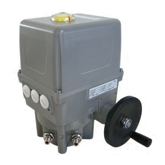
Motorized Rotary Actuator baelz 375-E42 2. PRODUCT DESCRIPTION 2.1 Identification Each actuator has a nameplate showing specifications regarding the maximum operating conditions of the device and a unique, order-related serial number (F no.). Fig. 1: Baelz nameplate for motorized actuators 1.7 Motorized rotary actuator The baelz 373-E42 is a motorized rotary actuator for flow control applications requiring a 90° rotation, such as those using drive butterfly valves or ball valves. The actuators are designed for highly accurate positioning in an industrial environment. Manual adjustment can be carried one-handed and without use of a clutch. The travel-dependent and/or torque-dependent limit switches can be individually configured. -
Page 7: Accessories And Options
Motorized Rotary Actuator baelz 375-E42 3.2 Accessories and options Table 2. Options for Actuators Two additional limit switches for signalling end positions or intermediate positions, freely adjustable, 2EZ-Fg max. 250 V AC, rating for resistive load max. 10 A, for inductive load max. 5 A Fg5k 5 kΩ potentiometer, linearity error ≤ 0.5%, max. 1.5 W, contact current 30 mA Digital positioner for actuator control, self adapting... -
Page 8: Assembly
Motorized Rotary Actuator baelz 375-E42 4. ASSEMBLY Make sure that the specifications on the nameplate correspond to those in the order documents! Attention 4.1 Fitting position Do not mount rotary actuators "head down" below the valve. Allow for about 200 mm space above the cover at the site of installation. -
Page 9: Principle Of Operation
Motorized Rotary Actuator baelz 375-E42 4.3 Principle of operation 4.3.1 Manual adjustment By turning the crank wheel the position of the actuator can be adjusted. This also turns the motor. Only carry out manual adjustment when the motor is not in motion. If a positioner is used, the actuator will automatically move back to the original position. -
Page 10: Electrical Connection
Motorized Rotary Actuator baelz 375-E42 4.4 Electrical connection Risk of electric shock! Danger Use an appropriate power supply to ensure that no hazardous voltage can enter the device during normal operation or in the event of a system failure or defective system components. -
Page 11: Commissioning
Motorized Rotary Actuator baelz 375-E42 5. COMMISSIONING Compare the actuator torque and the set travel with the technical specifications of the valve. Overloading can lead to serious damage to the valve. Watch out for moving parts during assembly and adjustment. Risk of injury and substantial material damage. The rotary actuator is factory set to a rotational travel of 90°. Actuators with positioners are supplied with a control input signal of 0-10 unless otherwise stipulated upon ordering. -
Page 12: Switching Off In End Positions
Motorized Rotary Actuator baelz 375-E42 5.3.2 Switching off in end positions Risk of electric shock! Danger If the switches in the actuator are not factory-wired, check proper switching off in end positions: With the cover removed, the rotary actuator may only be operated briefly for test runs or when performing absolutely essential adjustments on electrical components, such as potentiometer, limit switches or positioning electronics. -
Page 13: Retrofitting Of Additional Components
Motorized Rotary Actuator baelz 375-E42 6. RETROFITTING OF ADDITIONAL COMPONENTS 6.1 Retrofitting of potentiometer Disconnect actuator from power supply before starting work! Danger 1. Remove capacitor bracket. 2. If the actuator is equipped with a heating element, the potentiometer retaining plate [5] is already fitted and can be used for potentiometer assembly. Put potentiometer R1 [1] into retaining plate [5] and fasten with a lock washer and nut. -
Page 14: Retrofitting Of Two Additional Travel Switches (2Ez)
Motorized Rotary Actuator baelz 375-E42 6.2 Retrofitting of two additional travel switches (2EZ) Disconnect actuator from power supply before starting work! Danger 1. Remove the two allen screws [1] on the main switch board. Replace them with two spacer bolts [3]. 2. -
Page 15: Fitting The 7020A Digital Postioner
Motorized Rotary Actuator baelz 375-E42 6.3 Fitting the 7020A digital postioner Disconnect actuator from power supply before starting work! Danger 1. Remove the two screws indicated below. 2. Replace the screws with the spacer bolts spacer bolt M4 x 38 mm spacer bolt washer 1.6mm M4 x 85 mm... - Page 16 Motorized Rotary Actuator baelz 375-E42 1. Fix the isolation panel with the 4 plastic countersunk screws. Tighten gently, so as not to damage the screw thread. 2. Fit the 7020A digital positioner circuit board. To do this, place the plastic spacer sleeves over the four threaded holes in the corners of the isolation panel.
- Page 17 Motorized Rotary Actuator baelz 375-E42 3. Wire up the circuit board and the actuator using the wiring provided and according to the wiring diagram provided. 4. After fitting the digital positioner, stick the wiring diagram onto the inside of the actuator cover as shown. W. Baelz & Sohn GmbH & Co. · Koepffstrasse 5 · 74076 Heilbronn · Germany · www.baelz.de Seite | Page 17 |...
-
Page 18: Digital Positioner 7020A
Motorized Rotary Actuator baelz 375-E42 7. DIGITAL POSITIONER 7020A 7.1 Intended use The digital positioner baelz 7020A controls the actuator according to the value of the control signal: 0(2)-10 V, 0(4)-20 mA To ensure use for the purpose intended, check that the above type identification corresponds to the nameplate on the positioner before starting any activities. The technical specifications of the positioner and the power supply requirements are the indicated on the name plate. Any use other than the intended use stated above, use for different tasks, and operation with other power sources than those permitted, is considered to be improper use. -
Page 19: Normal And Safety Modes
Motorized Rotary Actuator baelz 375-E42 7.2.4 Normal and safety modes In normal mode the position of the valve is controlled by the set value at analogue input AI2. The N↔S switch shown in the picture on the right is set to normal mode (N). In normal mode, no external control systems can be connected to terminals 12 and 14. Fig. 7: N↔S-switch 7.2.5 Safety mode: freeze protection and excessive temperature In safety mode the actuator can be sent to a safe position (extended / retracted, depending on the direction of action of the valve) in case of failure or malfunctioning of the microcontroller. -
Page 20: Allocation Of Connection Terminals
Motorized Rotary Actuator baelz 375-E42 Fig. 10: Wiring diagram with digital positioner baelz 7020A 7.3.2 Allocation of connection terminals Terminal Allocation Notes 2, 3 supply terminals See wiring diagram for correct allocation. 4, 5, 12, 14 Can be allocated to an For external control, the overriding external control N↔S switch must be set... -
Page 21: Configuration Of The Dip Switches
Motorized Rotary Actuator baelz 375-E42 7.4 Configuration of the DIP switches The factory setting of the DIP switches is position 0, as shown. Switch Function Position 1 "ON" Position 0 DIP 1 Set value input: voltage, V or current, mA? current, mA voltage, V DIP 2... -
Page 22: Details On Dip Switches
Motorized Rotary Actuator baelz 375-E42 7.4.1 Details on DIP switches DIP1 and DIP2: are interpreted together: DIP1: 0 = voltage → DIP2: 0 = 0-10 V or 1 = 2-10 V. DIP1: 1 = current → DIP2: 0 = 0-20 mA or 1 = 4-20 mA. Either a voltage source can be connected to the U-terminal or a current source to the I-terminal. Never connect both at the same time. Attention DIP3: DIP switch 3 configures the analogue outputs AO1 and AO2 (see wiring diagram, Fig. - Page 23 Motorized Rotary Actuator baelz 375-E42 [0 0 0] [0 1 1]* [1 1 1]* open open open open open shut shut shut shut shut 100 % 100 % 100 % input signal 11-point Split range Split range Linear Inverse linear characteristic split 50 % split 33 %...
-
Page 24: Commissioning
Motorized Rotary Actuator baelz 375-E42 7.5 Commissioning 7.5.1 Quick start guide ↑ 1. Set DIP switches 2. Connect to supply 3. Start initialization run 7.5.2 Initialization run If the unit is not initialized, the green LED flashes. The red LED is lit when the position of the potentiometer is not ideal for an initialization run. (See section 7.5.3 for meaning of LED signals.) An initialization run can still be carried out, but it will take approx. 1x valve travel time longer. During a successful initialization run, the actuator is moved to both of its end positions. The potentiometer and the position of the actuator are synchronized and values for actuator travel time and switching hysteresis are determined. -
Page 25: Meaning Of Led Signals
Motorized Rotary Actuator baelz 375-E42 7.5.3 Meaning of LED signals green LED red LED Meaning signal signal green off Unit is switched off. red off green off Initialization run in progress. red on green Unit is not initialized. Potentiometer in ideal position for initialization run (between 7.5 and flashing 17.5%). red off green Unit is not initialized. -
Page 26: Errors
Motorized Rotary Actuator baelz 375-E42 7.6 Errors 7.6.1 Errors after an initialization run Following a successful initialization run, only the green LED is lit. If the red LED is flashing, this indicates an error following an unsuccessful initialization run. The first error to occur during initialization is shown. If the green LED is lit, the unit had already been initialized before the current initialization run. If the green LED is flashing, the unit had not been successfully initialized previously. The red LED shows errors occuring during initialization as follows: Error code 1: interval interval... -
Page 27: Errors During Normal Positioner Operation
Motorized Rotary Actuator baelz 375-E42 7.6.2 Errors during normal positioner operation The green LED is lit during normal positioner operation. A flashing red LED shows an error during normal positioner operation. For this, DIP switch 12 must be set to 0. The red LED indicates errors during normal positioner operation as follows: = long flash, = short flash) Error code 1: interval interval etc. -
Page 28: Technical Specifications
Motorized Rotary Actuator baelz 375-E42 7.7 Technical Specifications Table 4. Technical Specifications, baelz 7020A 230 VAC -15 % / +10 %, 50 / 60 Hz, Supply voltage option: 115 VAC 50 / 60 Hz, 24 VAC 50 / 60 Hz Fuse internal 1,6 A/T (slow-blow) Power consumption approx. 5 VA IP rating IP 42 Ambient temperature 0 to 50 °C Transport / storage temp. - 25 to +65 °C Ambient humidity 5 to 90 % relative humidity. (non-condensing) Dimensions WxHxD approx. -
Page 29: Spare Parts
Motorized Rotary Actuator baelz 375-E42 8. SPARE PARTS Pos. Bezeichnung Spare Part Pos. Bezeichnung Spare Part Drehwinkelskala turn gauge 33.2 Kondensator capacitor 2.2.1 Aluminiumhaube aluminium cover 33.3 Winkel capacitor bracket 2.2.2 Sichtfenster inspection glass 34.1 Schalterplatine switch board 2.2.4 Sicherungsring circlip Kunststoffhaube plastic cover... -
Page 30: Decommisioning And Disposal
Motorized Rotary Actuator baelz 375-E42 9. DECOMMISIONING AND DISPOSAL Dispose of the digital positioner in accordance with the relevant, country-specific regulations and laws.. 10. TROUBLESHOOTING If the actuator does not work properly, proceed as follows to correct the problem: 1. Check that the actuator is correctly installed. 2. Check the actuator settings and the specifications on the nameplate. 3. Correct the problems as specified in the checklist (page 31). 4. -
Page 31: Checklist For Operational Malfunctions
Motorized Rotary Actuator baelz 375-E42 10.1 Checklist for operational malfunctions Malfunction Cause Action required Power failure Determine the cause and correct the problem. Defective fuse (in control cabinet) Determine the cause and correct the problem, replace the fuse. Rotary actuator incorrectly connected Re-connect as specified on circuit diagram (inside cover). Short circuit caused by humidity Determine the cause, dry the rotary actuator;... -
Page 32: Dimensional Drawings
Motorized Rotary Actuator baelz 375-E42 11. DIMENSIONAL DRAWINGS ~ 19 mm for 90° Square coupling □17 mm ØD3 Mmax (mm) (mm) (Nm) F 04 F 05 F 07 ØD3 F 10 Anschlussmaße ISO5211 D3 (mm) D4 (mm) h2 (mm) Mmax (Nm) W. Baelz & Sohn GmbH & Co. · Koepffstrasse 5 · 74076 Heilbronn · Germany · www.baelz.de Seite | Page 32 |...
Need help?
Do you have a question about the BA 375-E42 and is the answer not in the manual?
Questions and answers