Table of Contents
Advertisement
Advertisement
Table of Contents

Related Manuals for Baelz Automatic 373-E07


Summary of Contents for Baelz Automatic 373-E07
- Page 1 Operating Instructions BA 373-E07 Motorized Linear Actuator baelz 373-E07 Technical specifications subject to change without notice Copyright according to ISO 16016 W. Baelz & Sohn GmbH & Co. · Koepffstrasse 5 · 74076 Heilbronn · Germany · www.baelz.de Seite | Page...
-
Page 2: Table Of Contents
Motorized Linear Actuator baelz 373-E07 Table of Contents 1. SAFETY 1.1 Intended use 1.2 Instructions for the operator 1.3 Personnel 1.4 Before starting work 1.5 During operation 1.5.1 Transport, installation and assembly 1.5.2 Maintenance and repair 1.6 Working environment 2. PRODUCT DESCRIPTION 2.1 Identification... - Page 3 Motorized Linear Actuator baelz 373-E07 7. DIGITAL POSITIONER 7020 7.1 Intended use 7.2 Operational modes and operating options 7.2.1 Standard operation using DIP switches 7.2.2 Standard operation using Modbus VT100 or direct addressing 7.2.3 Modbus mode 7.2.4 Normal and safety modes 7.2.5 Safety mode: freeze protection and excessive temperature...
-
Page 4: Safety
Application instructions and other useful information. 1.1 Intended use Baelz 373-E07 motorized linear actuators are controlled by three-point control or constant control in combination the digital positioner baelz 7020. The linear actuators of the series described in this document are intended for the stroke adjustment of valves. -
Page 5: Personnel
Motorized Linear Actuator baelz 373-E07 1.3 Personnel Only qualified personnel may work on this linear actuator or in its vicinity. Qualified persons are deemed to be persons who are familiar with the installation, assembly, commissioning and operation or maintenance of the actuators and have the appropriate qualifications for their job. Necessary or prescribed qualifications include, but are not limited to: ● Training / instruction and the authorization to switch electric circuits and devices / systems on and off in accordance with EN 60204 (DIN VDE 0100 / 0113) and the technical safety standards ●... -
Page 6: Product Description
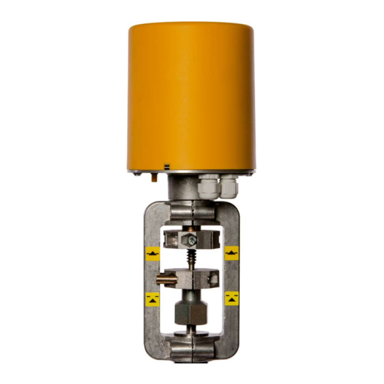
Actuator speed and power consumption depend on supply frequency (Hz). 2.2 Motorized linear actuator The baelz 373-E07 is a motorized linear actuator with load-dependent limit switches. The actuators are designed for highly accurate positioning in an industrial environment. They come complete with a manual adjustment device and a wide range of options and additional extras is available. -
Page 7: Technical Specifications
Motorized Linear Actuator baelz 373-E07 2.3 Technical Specifications Table 2. Technical Specifications, baelz 373-E07 E07-20-06-S21/L E07-20-18-S21/L E07-07-130-S21/L Actuating force 2000 2000 Positioning speed mm/min Supply voltage 24 V / 115 V / 230 V 50/60 Hz ± 10 % Power consumption (230 V) VA 11.7 Operating mode acc. to IEC 34-1 S1 - 100 %... -
Page 8: Options And Extras
Motorized Linear Actuator baelz 373-E07 2.4 Options and Extras Table 3. Options and Extras, baelz 373-E07 Option / Extra Description Remarks 2EZ-V2 2 limit switches with position indicator Mf-FgA Multiturn potentiometer А= 200 Ω, 5 kΩ, 1 kΩ Please specify resistance when ordering 2 limit switches with position indicator... -
Page 9: Operating Conditions
Motorized Linear Actuator baelz 373-E07 2.6 Operating conditions The actuators are suitable for installation in industrial plants and in waterworks and power plants with a low pollutant concentration. When used outdoors, the actuator must be protected with an additional cover against ●... -
Page 10: Assembly
Motorized Linear Actuator baelz 373-E07 4. ASSEMBLY Make sure that the specifications on the nameplate correspond to those in the order documents! Attention 4.1 Fitting position When fitting with the connecting rod in horizontal position, fit the linear actuator such that the sides of the yoke are positioned one above the other in the vertical plane. -
Page 11: Assembly With The Valve
Motorized Linear Actuator baelz 373-E07 4.2 Assembly with the valve Prior to assembly, check that: ● the operating conditions comply to the specifications of the linear actuator. ● the valve is complete (yoke on actuator or on valve). ● the connections on valve and actuator match. The linear actuator is supplied with the spindle retracted. -
Page 12: Principle Of Operation
Motorized Linear Actuator baelz 373-E07 4.3 Principle of operation Motorized linear actuators to operate control valves for flow regulation applications in control and process technology. The self-locking threaded spindle/spindle nut is driven by an electric motor via a gearbox. This converts the rotary movement into a linear movement. Load- dependent limit switches dictate the end positions 4.3.1 Manual adjustment... -
Page 13: Electrical Connection
Motorized Linear Actuator baelz 373-E07 4.4 Electrical connection Risk of electric shock! Danger Use an appropriate power supply to ensure that no hazardous voltage can enter the device during normal operation or in the event of a system failure or defective system components. -
Page 14: Commissioning
Motorized Linear Actuator baelz 373-E07 5. COMMISSIONING Pay attention to moving parts during fitting and adjustment. Risk of injury and substantial material damage. Warning Actuators which are supplied fitted with a valve are set to the appropriate valve stroke length. When an actuator with a 7020 digital positioner is fitted... -
Page 15: Retrofitting Of Optional Extras
Motorized Linear Actuator baelz 373-E07 6. RETROFITTING OF OPTIONAL EXTRAS Disconnect actuator from power supply before starting work! Danger 6.1 Fitting a potentiometer Set consists of: ● 1x potentiometer, 200 Ω, 1 kΩ or 5 kΩ ● 1x Torx screw T20 Fig. 4: E07 actuator with cover removed ●... -
Page 16: Fitting 2 Additional, Travel-Dependent Limit Switches (2Ez)
Motorized Linear Actuator baelz 373-E07 ● Fix the potentiometer with the Torx T20 button screw (Fig. 6, below) ● Lay the wiring between motor and terminal block assembly and wire the potentiometer up: terminal 91 = red, terminal 92 = brown, terminal 93 = blue (Fig. 7, below). Trim the ferrules if necessary. ● Secure the wiring with cable ties. -
Page 17: Adjusting The Switching Points
Wire up the outputs E1-E3 or E4-E6 (wiring diagram Fig. 15). Fig. 15: Wiring diagram baelz 373-E07 Fig. 14: Adjusting the with 2EZ and potentiometer switching cams W. -
Page 18: Fitting A Potentiometer To The 2Ez Assembly
Motorized Linear Actuator baelz 373-E07 6.3 Fitting a potentiometer to the 2EZ assembly Material: ● 1x Potentiometer assembly, 200 Ω, 1 kΩ oder 5 kΩ (Fig. 16). connector bushing anti-rotation lever earthing plug Fig. 16: Potentiometer assembly for 2 additional travel limit switches ● Set the valve / actuator to the 50% position (see section 4.3.1 on manual adjustment) ● Set the potentiometer to the 50% position. To do this, turn the potentiometer shaft until an endstop is reached, then turn it back by just under half a rotation (of just under one rotation in total). -
Page 19: Digital Positioner 7020
Motorized Linear Actuator baelz 373-E07 ● Tighten the lower grub screw in the connector bushing with a 1.5 mm Allen key. Check that the top grub screw ist tight. Do not loosen the top grub screw. ● Connect the potentiometer to the terminal block of the actuator: terminal 91 = red, terminal 92 = brown, terminal 93 = blue (Fig. 19, below). -
Page 20: Operational Modes And Operating Options
Motorized Linear Actuator baelz 373-E07 7.2 Operational modes and operating options For further information and additional functions, see baelz 7020 operating instructions. Tip: 7.2.1 Standard operation using DIP switches The DIP switches can be used to carry out standard configurations and operations (see section 7.4 When DIP switch 11 is set to 0, the 7020 is in the standard operational mode. -
Page 21: 3-Point Control With A Continuous Output Signal
Motorized Linear Actuator baelz 373-E07 7.2.6 3-point control with a continuous output signal 1. Set the positioner up and wire to power supply as described previously and initialize as described in section 7.5.2. 2. Set the N↔S switch (Fig. 20, page 20 to "S" 3. Wire as shown in Fig. 21 (the positioner must remain connected to the power supply throughout). -
Page 22: Wiring Diagrams And Terminal Allocation
Motorized Linear Actuator baelz 373-E07 7.3 Wiring diagrams and terminal allocation Disconnect actuator from power supply before starting work. See also section 4.4. Danger 7.3.1 Wiring diagrams Fig. 23: Wiring diagram basic actuator baelz 373- E07 with potentiometer (Fg) and 2 additional... -
Page 23: Terminal Allocation
Motorized Linear Actuator baelz 373-E07 7.3.2 Terminal allocation E5 E6 92 93 98 99 22 23 24 25 26 Normal and safety modes, see section 7.2.4 Fig. 25: Terminal numbering Table 5. Terminal allocation Terminal Allocation Notes 2, 3 supply terminals See wiring diagram on page 22 for correct allocation. -
Page 24: Configuration Of The Dip Switches
Motorized Linear Actuator baelz 373-E07 7.4 Configuration of the DIP switches The factory setting of the DIP switches is position 0, as shown. Switch Function Position 1 "ON" Position 0 DIP 1 Set value input: voltage, V or current, mA? -
Page 25: Details On Dip Switches
Motorized Linear Actuator baelz 373-E07 7.4.1 Details on DIP switches DIP1 and DIP2: are interpreted together: DIP1: 0 = voltage → DIP2: 0 = 0-10 V or 1 = 2-10 V. DIP1: 1 = current → DIP2: 0 = 0-20 mA or 1 = 4-20 mA. Either a voltage source can be connected to the U-terminal or a current source to the I-terminal. Never connect both at the same time. - Page 26 Motorized Linear Actuator baelz 373-E07 [0 0 0] [0 1 1]* [1 1 1]* open open open open open shut shut shut shut shut 100 % 100 % 100 % input signal 11-point Split range Split range Linear Inverse linear characteristic split 50 % split 33 % Fig. 27: Graphical illustration of selection of functions by DIP switches 7, 8 & 9 DIP10: An actuator characteristic can be used indirectly to change a valve characteristic.
-
Page 27: Commissioning
Motorized Linear Actuator baelz 373-E07 7.5 Commissioning 7.5.1 Quick start guide ↑ 1. Set DIP switches 2. Connect to supply 3. Start initialization run 7.5.2 Initialization run If the unit is not initialized, the green LED flashes. The red LED is lit when the position of the potentiometer is not ideal for an initialization run. (See section 7.5.3 for meaning of LED signals.) An initialization run can still be carried out, but it will take approx. -
Page 28: Meaning Of Led Signals
Motorized Linear Actuator baelz 373-E07 7.5.3 Meaning of LED signals green LED red LED Meaning signal signal green off Unit is switched off. red off green off Initialization run in progress. red on green Unit is not initialized. Potentiometer in ideal position for initialization run (between 7.5 and flashing 17.5%). -
Page 29: Errors
Motorized Linear Actuator baelz 373-E07 7.6 Errors 7.6.1 Errors after an initialization run Following a successful initialization run, only the green LED is lit. If the red LED is flashing, this indicates an error following an unsuccessful initialization run. The first error to occur during initialization is shown. If the green LED is lit, the unit had already been initialized before the current initialization run. If the green LED is flashing, the unit had not been successfully initialized previously. The red LED shows errors occuring during initialization as follows:... -
Page 30: Errors During Normal Positioner Operation
Motorized Linear Actuator baelz 373-E07 7.6.2 Errors during normal positioner operation The green LED is lit during normal positioner operation. A flashing red LED shows an error during normal positioner operation. For this, DIP switch 12 must be set to 0. The red LED indicates errors during normal positioner operation as follows: = long flash, = short flash) Error code 1: interval interval etc. -
Page 31: Technical Specifications
Motorized Linear Actuator baelz 373-E07 7.7 Technical Specifications Table 6. Technical Specifications, baelz 7020 230 VAC -15 % / +10 %, 50 / 60 Hz, Supply voltage option: 115 VAC 50 / 60 Hz, 24 VAC 50 / 60 Hz Fuse internal 1.6 A/T (slow-blow) Power consumption approx. 5 VA IP rating IP 42 Ambient temperature 0 to 50 °C Transport / storage temp. -
Page 32: Spare Parts
373-E07 all types Fig. 29: Spare parts Fig. 30: Spare parts baelz 373-E07 type 6 baelz 373-E07 type 18 W. Baelz & Sohn GmbH & Co. · Koepffstrasse 5 · 74076 Heilbronn · Germany · www.baelz.de Seite | Page... - Page 33 Motorized Linear Actuator baelz 373-E07 Tabelle 1. Ersatzteile / Spare parts baelz 373-E07 Sachnr. Bestellnr. Pos. Bezeichnung Description part number order number Motoreinheit Typ RSM 63/8 SG motor unit type RSM 63/8 SG incl. einschl. Motorritzel KT 24669 + motor pinion KT 24669 +...
-
Page 34: Decommisioning And Disposal
Motorized Linear Actuator baelz 373-E07 9. DECOMMISIONING AND DISPOSAL Dispose of the digital positioner in accordance with the relevant, country-specific regulations and laws.. 10. TROUBLESHOOTING If the actuator does not work properly, proceed as follows to correct the problem: 1. Check that the actuator is correctly installed. 2. Check the actuator settings and the specifications on the nameplate. 3. Correct the problems as specified in the checklist (page 35). -
Page 35: Checklist For Operational Malfunctions
Motorized Linear Actuator baelz 373-E07 10.1 Checklist for operational malfunctions Malfunction Cause Action required Power failure Determine the cause and correct the problem. Defective fuse (in control cabinet) Determine the cause and correct the problem, replace the fuse. Linear actuator incorrectly connected Re-connect as specified on circuit diagram (inside cover). -
Page 36: Dimensional Drawings
Motorized Linear Actuator baelz 373-E07 11. DIMENSIONAL DRAWINGS Fig. 31: Dimensional drawing Fig. 32: Dimensional drawing baelz E07 with S21 yoke baelz E07 with S21-L yoke and spindle Ø 10 mm and spindle Ø 16 mm W. Baelz & Sohn GmbH & Co. · Koepffstrasse 5 · 74076 Heilbronn · Germany · www.baelz.de...
Need help?
Do you have a question about the 373-E07 and is the answer not in the manual?
Questions and answers