
Related Manuals for Horizon Hobby E-Flite V-22 Osprey VTOL


Summary of Contents for Horizon Hobby E-Flite V-22 Osprey VTOL
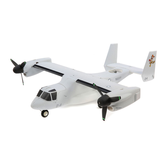
- Page 1 V-22 Osprey VTOL Instruction Manual Bedienungsanleitung Manuel d’utilisation Manuale di Istruzioni 68-251018-34821...
-
Page 2: Safety Precautions And Warnings
NOTICE All instructions, warranties and other collateral documents are subject to change at the sole discretion of Horizon Hobby, LLC. For up-to-date product literature, visit horizonhobby.com or towerhobbies.com and click on the support or resources tab for this product. Meaning of Special Language:... -
Page 3: Table Of Contents
Quick Start Information Transmitter Set up your transmitter using the transmitter setup table Setup 25-30mm from the leading edge of wing root as Center of Gravity shown in the Center of Gravity section (CG) (CG must be set with the motor nacelles in the Airplane Mode, forward position) Flight Timer 4 minutes... -
Page 4: Prefl Ight
Prefl ight 1. Remove and inspect contents. 9. Make sure linkages move freely. 2. Read this instruction manual thoroughly. 10. Perform the Control Direction Test with the transmitter. 3. Charge the fl ight battery. 11. Perform the stability system control direction test with the aircraft. 4. -
Page 5: Battery Installation And Esc Arming
Battery Installation and ESC Arming Battery Selection ® We recommend the E-fl ite 800mAh 11.1V 3S 30C Li-Po battery (EFLB8003SJ30). Refer to the Optional Parts list for other recommended batteries. If using a battery other than those listed, the battery should be within the range of capacity, dimensions and weight of the E-fl... -
Page 6: Flight Control Direction Test
Flight Control Direction Test This test ensures that the fl ight control system is functioning properly. Aircraft Movement Control Surface Reaction Assemble the aircraft, bind your transmitter to the receiver, and ensure the aircraft is in Airplane Flight Mode and throttle cut is active before performing this test. -
Page 7: Flight Conditions
Adjusting the Nacelle Alignment Pushrod Length Adjustment Servo Horn Adjustment Both servo horns must be at similar angles when in airplane mode for the The pushrods for the nacelle linkages should be 39-40mm long from the clevis aircraft to transition from multirotor to airplane mode correctly. pin to the z-bend. -
Page 8: Linkage Settings And Flight Trimming
Linkage Settings and Flight Trimming The table to the right shows the factory settings for the control horns and Control Horns Servo Arms servo arms. Fly the aircraft at factory settings before making any changes to the control linkages. Ailerons Trim 1. - Page 9 Aileron Rear view Rear view Right Left Aileron right Aileron left Rudder Top view Top view Yaw left Yaw right Rudder right Rudder left Airplane Flight Mode Throttle Left side view Left side view Faster Slower Throttle up Throttle down Elevator Left side view Left side view...
-
Page 10: Flying Your Aircraft
Flying Your Aircraft Consult local laws and ordinances before choosing a fl ying location. To transition to Multirotor Flight Mode from Airplane Flight Mode reduce Range Check your Radio System the airspeed, change the switches on your transmitter to select the Multirotor Before you fl... -
Page 11: Post Flight
Post Flight 1. Disconnect the fl ight battery from the fl ight controller 5. Repair or replace all damaged parts. (Required for safety and battery life). 6. Store the fl ight battery apart from the aircraft and monitor the battery charge. 2. -
Page 12: Motor Service
Motor Service CAUTION: Always disconnect the fl ight battery before performing TOP VIEW motor service. Main Motor Removal 1. Loosen the two screws clamping the motor nacelle to the torque rod. 2. Slide the motor nacelle off the torque rod. 3. -
Page 13: Receiver, Servo, And Esc Connection Diagram
Receiver, Servo, and ESC Connection Diagram Left Motor Tilt Servo Right Motor Tilt Servo Left Aileron Servo Right Aileron Servo Elevator Servo – Serial receiver connector – – No connection + – – + – – – – Rear Motor ESC Right Main Motor ESC Left Main Motor ESC IMPORTANT: Only use the recommended ESCs for this aircraft, they are powered... -
Page 14: Troubleshooting Guide
Troubleshooting Guide Problem Possible Cause Solution Throttle not at idle and/or throttle trim too high Reset controls with throttle stick and throttle trim at lowest setting Aircraft will not respond Throttle servo travel is lower than 100% Make sure throttle servo travel is 100% or greater to throttle but responds Throttle channel is reversed Reverse throttle channel on transmitter... -
Page 15: Ama National Model Aircraft Safety Code
AMA National Model Aircraft Safety Code Effective January 1, 2014 A. GENERAL B. RADIO CONTROL A model aircraft is a non-human-carrying aircraft capable of sustained fl ight 1. All pilots shall avoid fl ying directly over unprotected people, vessels, vehicles in the atmosphere. -
Page 16: Limited Warranty
Product, (iv) attempted service by and is accepted at our facility. An Online Service Request is available at http:// anyone other than a Horizon Hobby authorized service center, (v) Product not www.horizonhobby.com/content/service-center_render-service-center. If you... -
Page 17: Contact Information
Compliance Information for the European Union V-22 Osprey BNF Basic (EFL9650) V-22 Osprey PNP (EFL9675) EU Compliance Statement: Horizon Hobby, LLC hereby declares that this EU Compliance Statement: Horizon Hobby, LLC hereby declares product is in compliance with the essential requirements and other relevant that this product is in compliance with the essential requirements provisions of the EMC Directive. -
Page 18: Exploded View
Exploded View / Explosionszeichnung / Vue Éclatée / Vista Esplosa V-22 Osprey VTOL... -
Page 19: Replacement Parts
Replacement Parts • Ersatzteile • Pièces de rechange • Pezzi di ricambio Part # / Nummer Numéro / Codice Description Beschreibung Description Descrizione 1 EFL9601 Fuselage w/Plastics: V-22 Osprey Rumpf mit Kunststoffen: V-22 Osprey Fuselage avec plastiques : V-22 Osprey Fusoliera con plastica: V-22 Osprey 2 EFL9602 Wing w/Plastics: V-22 Osprey Tragfl... - Page 20 © 2019 Horizon Hobby, LLC. E-fl ite, AS3X, DSM, DSM2, DSMX, the DSMX logo, Bind-N-Fly, BNF, the BNF logo, Plug-N-Play, ModelMatch, Dynamite, EC3, Prophet, Focal and the Horizon Hobby logo are trademarks or registered trademarks of Horizon Hobby, LLC. The Spektrum trademark is used with permission of Bachmann Industries, Inc.
Need help?
Do you have a question about the E-Flite V-22 Osprey VTOL and is the answer not in the manual?
Questions and answers