
Subscribe to Our Youtube Channel
Related Manuals for Horizon Hobby Valiant 1.3m


Summary of Contents for Horizon Hobby Valiant 1.3m
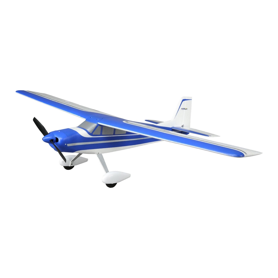
- Page 1 Valiant 1.3m ™ Instruction Manual Bedienungsanleitung Manuel d’utilisation Manuale di Istruzioni SAFE Select Technology, Optional Flight Envelope Protection ®...
- Page 2 NOTICE All instructions, warranties and other collateral documents are subject to change at the sole discretion of Horizon Hobby, LLC. For up-to-date product literature, visit horizonhobby.com or towerhobbies.com and click on the support or resources tab for this product. Meaning of Special Language: The following terms are used throughout the product literature to indicate various levels of potential harm when operating this product: NOTICE: Procedures, which if not properly followed, create a possibility of physical property damage AND little or no possibility of injury.
-
Page 3: Table Of Contents
Box Contents Quick Start Information Transmitter Set up your transmitter using the Setup transmitter setup chart Hi Rate Low Rate p22mm p17mm q18mm q14mm Dual Rates 25mm 20mm 38mm 25mm Landing Takeoff Flaps q=28mm q=14mm Center of 65mm +/-3mm back from leading edge of Gravity (CG) wing at the fuselage. -
Page 4: Select Technology
SAFE Select Technology ® The evolutionary SAFE ® Select technology can offer an extra level of protection so you can perform the first flight with confidence. No complex transmitter programming is required. Just follow the simple bind process to make the SAFE Select system active. When activated, bank and pitch limitations keep you from over-controlling and automatic self-leveling makes recovery from risky or confusing attitudes as simple as releasing the sticks. -
Page 5: Model Assembly
Model Assembly Main Landing Gear Installation Remove the battery compartment door (A) from the bottom of the fuselage. Slide the pre assembled landing gear (B) into the fuselage as shown. Secure with the 4 screws (C). Re-install the battery hatch. Tail Installation Install the Vertical stab (A) over the Horizontal stab (B) by sliding the 2 plastic tabs down through the holes in the horizontal stab, creating a... - Page 6 Model Assembly Continued Wing Installation Slide the 1 large (A) and 1 small (B), carbon fiber wing tubes into one wing half and then join the 2 halves together. Connect the Flaps and Aileron connectors to respective Y-harnesses connected to the receiver. The left and right servos can be connected to either side of a Y-harness.
- Page 7 Float Installation (Optional) Float Assembly Install the 2 cross members (A) and the front and rear struts (B) on one float as shown and secure with 4 included screws (C). Install the other float onto the assembled struts as in Step 1 above. IMPORTANT: The front strut is taller than the rear strut.
-
Page 8: Control Horn And Servo Arm Settings
Ailerons Ailerons Control Horn and Servo Arm Settings Flaps Flaps The table to the right shows the factory settings for the control horns and servo Horns Arms arms. Fly the aircraft at factory settings before making changes. NOTICE: If control throws are changed from the factory settings, the AR631 gain values may need to be adjusted. -
Page 9: Battery Installation And Esc Arming
Battery Installation and ESC Arming Battery Selection We recommend theSpektrum 2200mAh 11.1V 3S 30C Li-Po battery ® (SPMX22003S30). Refer to the Optional Parts List for other recommended batteries. If using a battery other than those listed, the battery should be within the range of capacity, dimensions and weight of the E-flite Li-Po battery packs to fit in the fuselage. -
Page 10: Transmitter And Receiver Binding / Switching On And Off Safe Select
Transmitter and Receiver Binding / Switching ON and OFF SAFE Select Switching ON SAFE Select Binding Sequence This product requires an approved Spektrum DSM2 /DSMX compatible ™ ® ® transmitter. Visit www.bindnfly.com for a complete list of approved transmitters. The aircraft has an optional SAFE Select feature, which can be switched ON or OFF easily by binding in a specific manner as described below. -
Page 11: Select Switch Designation
SAFE Select Switch Designation ® SAFE Select technology can be easily assigned to any open switch on your ® Mode 1 and 2 Transmitters transmitter. With this new feature, you now have the flexibility to enable or dis- able the technology while in flight. IMPORTANT: Before assigning your desired switch, ensure that the travel for that channel is set at 100%. -
Page 12: In Flight Trimming
In Flight Trimming During your first flight, trim the aircraft for level flight at 3/4 throttle with flaps up. Make small trim 3 Seconds adjustments with your transmitter’s trim switches to straighten the aircraft’s flight path. After adjusting trim, do not touch the control sticks for 3 seconds. This allows the receiver to learn the correct settings to optimize AS3X performance. -
Page 13: Center Of Gravity (Cg)
Center of Gravity (CG) The CG location is measured from the leading edge of the wing at the root. This CG location has been determined with the recommended Li-Po battery 65mm +/- 3mm (SPMX22003S30) installed all the way forward in the battery compartment. back from leading edge of wing at the fuselage. -
Page 14: Post Flight
Post Flight 1. Disconnect the flight battery from the ESC (Required for Safety and 5. Repair or replace all damaged parts. battery life). 6. Store the flight battery apart from the aircraft and monitor the battery charge. 2. Power OFF the transmitter. 3. -
Page 15: Troubleshooting Guide
Troubleshooting Guide Problem Possible Cause Solution Throttle not at idle and/or throttle trim too high Reset controls with throttle stick and throttle trim at lowest setting Aircraft will not re- Throttle servo travel is lower than 100% Make sure throttle servo travel is 100% or greater spond to throttle but responds to other Throttle channel is reversed... -
Page 16: Ama National Model Aircraft Safety Code
AMA National Model Aircraft Safety Code Academy of Model Aeronautics National Model Aircraft Safety Code Effective January 1, 2018 A model aircraft is a non-human-carrying device capable of sustained flight within visual line of sight of the pilot or spotter(s). It may not exceed limitations of this code and is intended exclusively for sport, recreation, education and/or competition. -
Page 17: Limited Warranty
Limited Warranty What this Warranty Covers – Horizon Hobby, LLC, (Horizon) warrants to the original the event that you may need any assistance. For questions or assistance, please visit purchaser that the product purchased (the “Product”) will be free from defects in our website at www.horizonhobby.com, submit a Product Support Inquiry, or call the... -
Page 18: Contact Information
It should be deposited at an appropriate facility to enable recovery and recycling. EFL Valiant 1.3m PNP (EFL4975); Hereby, Horizon Hobby, LLC declares that the device is in compliance with the following: EU EMC Directive 2014/30/EU,... -
Page 19: Replacement Parts
Replacement Parts • Ersatzteile • Pièces de rechange • Pezzi di ricambio Part # | Nummer Description Beschreibung Description Descrizione Numéro | Codice EFL4951 Painted Valiant 1.3 fuse Painted Valiant 1.3 fuse Valiant 1.3 - Fuselage peint Fusoliera verniciata Valiant 1.3 EFL4952 Painted Valiant 1.3 wing Painted Valiant 1.3 wing... - Page 20 E-flite, Valiant, AS3X, DSM, DSM2, DSMX, the DSMX logo, Bind-N-Fly, BNF, the BNF logo, Plug-N-Play, SAFE, the SAFE logo, Z-Foam, ModelMatch, Dynamite, EC3, Prophet and the Horizon Hobby logo are trademarks or registered trademarks of Horizon Hobby, LLC. The Spektrum trademark is used with permission of Bachmann Industries, Inc.
Need help?
Do you have a question about the Valiant 1.3m and is the answer not in the manual?
Questions and answers
No s\n number in valiant manual