Table of Contents
Advertisement
Quick Links
INSTALLER: Leave this manual with the appliance.
CONSUMER: Retain this manual for future reference.
WARNING:
FIRE OR EXPLOSION HAZARD
Failure to follow safety warnings exactly could result in serious
injury, death, or property damage.
- Do not store or use gasoline or other ammable vapors and
liquids in the vicinity of this or any other appliance.
- WHAT TO DO IF YOU SMELL GAS
• Do not try to light any appliance.
• Do not touch any electrical switch; do not use any phone
in your building.
• Leave the building immediately.
• Immediately call your gas supplier from a neighbour's phone.
Follow the gas supplier's instructions.
• If you cannot reach your gas supplier call the fire department.
- Installation and service must be performed by a qualified
installer, service agency or the gas supplier.
This appliance may be installed in an aftermarket
permanently located, manufactured home (USA only)
or mobile home, where not prohibited by local codes.
This appliance is only for use with the type of gas
indicated on the rating plate. This appliance is
not convertible for use with other gases, unless a
certifi ed kit is used.
This appliance is suitable for installation in a
bedroom or bed sitting room.
WARNING:
If the information in these
instructions is not followed exactly, a fi re
or explosion may result causing property
damage, personal injury or death.
021115-40
Visit www.pacifi cenergy.net for the most up-to-date version of this manual
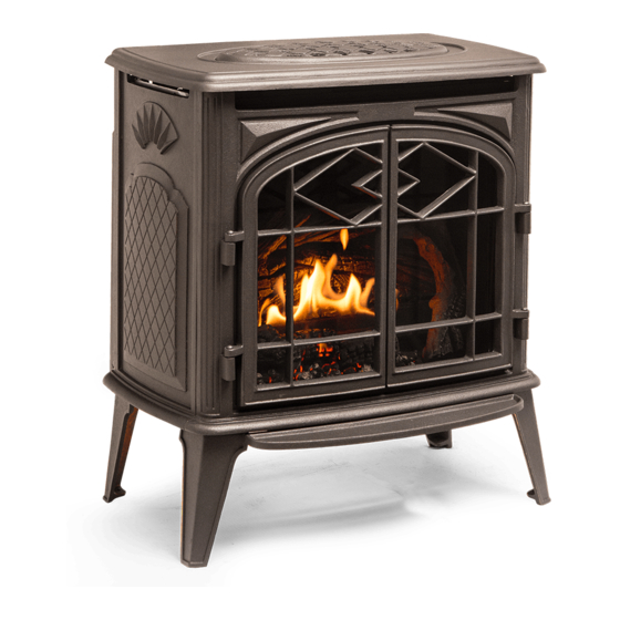
TRENTON
SERIAL #
MODEL: TRENTON
SERIES: A
FREESTANDING GAS STOVE
INSTALLATION AND OPERATING
INSTRUCTIONS
TRNT.BODYA
5055.45-A
Advertisement
Table of Contents

Related Manuals for Pacific energy trenton A series


Summary of Contents for Pacific energy trenton A series
- Page 1 INSTALLER: Leave this manual with the appliance. CONSUMER: Retain this manual for future reference. WARNING: TRENTON FIRE OR EXPLOSION HAZARD Failure to follow safety warnings exactly could result in serious injury, death, or property damage. - Do not store or use gasoline or other ammable vapors and liquids in the vicinity of this or any other appliance.
-
Page 2: Table Of Contents
Table of Contents Important note for the Commonwealth of Co-Linear venting ..........18 Massachusetts ............3 Venting components ......... 19 Trenton gas stove rear components ....20 Owners information Gas and electrical connection ......21 Caution ..............4 Screen mesh removal ........22 Safety .............. -
Page 3: Important Note For The Commonwealth Of Massachusetts
Important Note for the Commonwealth of Massachusetts: From Massachusetts Rules and Regulations 248 CMR 5.08: (a) For all side wall horizontally vented gas fueled equipment installed in every dwelling, building or structure used in whole or in part for residential purposes, including those owned or operated by the Commonwealth and where the side wall ex- haust vent termination is less than seven (7) feet above finished grade in the area of the venting, including but not limited to decks and porches, the following requirements shall be satisfied. -
Page 4: Owners Information
Owner information Congratulations on your purchase of a Pacific Energy Gas Stove. Your Trenton direct vent, Free-standing gas stove has been professionally installed by: Dealer name: ___________________________________ Phone Number: _________________________________ f you discover any problems with your gas stove contact your dealer immediately to have the unit repaired. -
Page 5: Safety
Owner information Safety Due to high temperatures, this gas stove should be located out of traffic and away from furniture and draperies. Children and adults should be alerted to the hazards of high surface temperatures and should stay away to avoid burns or clothing ignition. Young children should be carefully supervised when they are in the same room as the gas stove. -
Page 6: Manufactured (Mobile) Home
Owner information Manufactured (Mobile) Homes In some jurisdictions, the Trenton gas stove may be installed in Manufactured Homes after the “first sale”. Consult local codes for approval. The gas stove must be fastened in place. Install in accordance with the current standard Mobile Homes, CAN/CSA Z240 MH (in CANADA), and the Manufacturer’s Home Construction and Safety Standard, Title 24 CFR, Part 3280 or the current Standard for Fire Safety Criteria for Manufactured Home Installations, Sites and Communities ANSI/NFPA 501A (in the USA). -
Page 7: Remote Control System
Owner information Remote Control System System Description The Profl ame Remote Control System consists of three elements: Profl ame Remote Transmitter. Profl ame Integrated Fireplace Control (IFC) module. A wiring harness to connect the IFC to the gas valve and stepper motor. Transmitter (Remote Control with LCD Display) The Profl ame Remote Transmitter uses a streamline design with a simple button layout and informative LCD display (Figure 1). - Page 8 Owner information Temperature indication Display With the remote transmitter in the “OFF” position, press the thermostat key and the mode key at the same time. Look at the LCD screen on the remote transmitter to verify that a C or F is visible to the right of the room temperature display (Figure 3) &...
- Page 9 Owner information Remote Flame Control The Proflame has six (6) flame levels. With the system turned on, and the flame level at maximum in the gas stove, press the down arrow key once to reduce the flame height by one step until the flame is turned off.
- Page 10 Owner information Comfort Fan Speed Control If the gas stove is equipped with a hot air circulating fan, the speed of the fan can be controlled by the Profl ame System. The fan speed can be adjusted through six (6) speeds. To activate this function use the Mode Key (Figure 1) to index to the fan control icon (Figure 13).
-
Page 11: Warnings And Cautions
Owner information Low Battery Power Detection Remote Transmitter The life span of the remote control batteries depends on various factors: quality of the batteries used, the number of ignitions of the gas stove, the number of changes to the room thermostat set point, etc. -
Page 12: Maintenance
A replacement glass door can be obtained from your nearest Pacific Energy dealer. Do not substitute with any other type. To replace broken glass door, refer to Glass Door Removal on page 22 and Glass Door Installation on page 26. -
Page 13: Lighting Instructions
Owner information Lighting Instructions FOR YOUR SAFETY READ BEFORE LIGHTING WARNING: - Immediately call your gas supplier from a neighbour's phone. Follow If you do not follow these instructions exactly, a the gas supplier's instructions. fire or explosion may result causing property damage, - If you cannot reach your gas supplier, call the fire department. -
Page 14: Installer Information
Installer information Trenton Gas Stove Dimensions Dimensions 30 5/8 inches Height Width 26 3/4 inches Depth 21 15/16 inches Height to center of Flue Outlet 24 inches 26 3/4” 21 15/16” 30 5/8” 24” Figure 21: Trenton dimensions. 5055.45-A 021115-40 TRNT.BODYA... -
Page 15: Clearances To Combustibles
Installer information Clearances to combustibles Minimum Clearance to Combustible Materials INTERIOR SIDE WALL 4” INTERIOR BACK WALL 4 “ INTERIOR CEILING 18” VENTING PIPE CLEARANCE 1” 18” Note on corner placement: MIN. Refer to minimum clearances as shown in (Figure 22) & (Figure 23). Refer to 4”... -
Page 16: Vent Terminal Clearances
Installer information Vent Terminal Clearances Minimum clearances to the vent terminal must be maintained as shown in (Figure 24) and Roof Pitch VENT TERMINAL MINIMUM CLEARANCES Table. Measure clearances to the nearest edge of TO ADJACENT STRUCTURES termination hood. 36" NOTE: Vent terminal must not be recessed (91.5 cm) 24"... -
Page 17: Trenton Co-Axial Venting Chart
Installer information Trenton Co-Axial Venting Chart Note: The vent must not exceed a total length of 30 feet. Any combination of rise and run may be used but must be constrained to the boundaries of this NO VENTING OPTION chart. A Maximum of three (3) 90°... -
Page 18: Co-Linear Venting
Installer information Co-Linear Venting Simpson Duravent High-Wind (cap style) Co-Linear Kit w/Flex (46DVA-CL33) or Simpson Duravent Prairie (cap style) Co-Linear Kit w/Flex (46DVA-CL33P) are High wind cap recommended for use with this appliance. Visit http://www.duravent.com for kit details. Co-Linear Venting Notes: Measure chimney height, cut ex liner (min.10’... -
Page 19: Venting Components
Installer information Venting Components NOTE: Mixing venting components from different manufacturers is inadvisable. Description Metal-Fab® Security Selkirk DuraVent EXCELDirect® Sure-Seal Secure Vent™ Direct-Temp™ DirectVent Pro® Galvanize Black Galvanized Black Galvanized Black Galvanized Black Galvanized Black 6” Pipe Length 4DL6 4DL6B 4D6B SV4L6 SV4LB6... -
Page 20: Trenton Gas Stove Rear Components
Installer information This gas stove is certified for use with 4” x 6⅝”coaxial venting components only. It is permitted to only use certified venting for this gas stove. See charts on page 19 for a list of approved venting components. Figure 30: Co-axial venting components. -
Page 21: Gas And Electrical Connection
Installer information Gas and Electrical Connections Note: Do not plug the Note: Do not turn on power cord in until the gas supply until installation has been installation has been completed. completed. Gas connection To make the required electrical and gas connections, start by positioning the gas stove. -
Page 22: Screen Mesh Removal
Installer information Packaging The Trenton gas stove comes with the ceramic panels and gas burner already installed. The log set and glowing embers are packaged in protective styrofoam and secured in place by the glass door and screen. The glass door and screen must be removed before the log set and embers can be accessed. - Page 23 Installer information Remove the mesh screen as described on page 22. Remove the wing nut bolts (Figure 37) securring the glass door retainer frame to the gas stove frame and tilt the glass door so that it can be removed (Figure 38). Remove the glass door together with the retainer frame that it is affixed to.
-
Page 24: Log Set Installation
Installer information Log Set Installation Installation of log set 1. Fill burner basket (Figure 42) with embers so that the baskets are filled and overflowing the burners’ front row (Figure 43). Reserve a small amount of embers for final placement. 2. - Page 25 Installer information Inset of tab. Figure 46: 3rd log placement. 4. Position 3rd log as shown in (Figure 46)making sure that the log does not cover the holes of the back row of the burner. The 3rd log has a hole in its underside which will fit onto a protruding tab on the burner (Figure 42).
-
Page 26: Glass Door Installation
Installer information (Figure 49) shows the burners’ back row as not being covered by the logs. At this time, the small amount of embers reserved at the beginning of log placement can be used to fill any left over spaces. NOTE: Although it is permisable to place a few embers between the back burner and the 3rd and 4th logs in order to hide the back burner,... -
Page 27: Screen Mesh Installation
Installer information Screen Mesh Installation Screen Mesh Installation The screen mesh is positioned between the glass door and the doors. It's purpose is to provide protection from the heat radiating from the glass door. The screen has a front side and a rear side and must be oriented correctly for a proper fit. - Page 28 Installer information The bottom edge of the screen mesh must fi t fi rmly into the channel provided Door for it in the fi re box frame. (Figure 57) Fire box side side shows the location of the screen mesh channel.
-
Page 29: Accent Lighting Glass Plates
Installer information Accent Lighting Glass Plates The Trenton Gas Stove comes with an assortment of glass plates of various colours. Accent lighting is controlled via the remote control transmitter included with the Trenton Gas Stove (Figure 1 on page 7). The glass plate tray is located underneath the Trenton (Figure 60) and is held in place by two wing nuts - one on each side of the tray. -
Page 30: Ifc Module
Installer information IFC Module The Profl ame 2 Integrated Fireplace Control (IFC) module is a device that allows automatic ignition and pilot fl ame supervision, and commands the functions of the hearth gas stove. It’s confi gured to control the ON/OFF main burner operation, giving the choice of both IPI (intermittent pilot ignition), and CPI (continuous pilot ignition) modes. -
Page 31: Damper Adjustment
Installer information Damper Adjustment Damper Adjustment Damper adjustment is located under the top cladding cover plate. (Factory setting is closed; slowly open and adjust as necessary to eliminate a sagging, - = closed sooting ame). + = open Figure 66: Trenton damper adjustment. Venturi Adjustment Venturi adjustment is accessible through an opening in the rear cover. -
Page 32: Gas Supply
Installer information Gas Supply Servicing of the gas stove can be performed from the rear of the unit by removing the access panel from the unit. Caution: The gas line should be installed by a qualified service person in accordance with all building codes. -
Page 33: Gas Pressure Testing Procedure
Installer information Gas Pressure Testing Procedure Note: To test the gas pressure, turn off the gas supply to the gas stove before loosening test point screws. Verify gas pressures with the gas stove lit and at the highest setting. 1. Remove back panel and locate the valve as seen in (Figure 69). 2. -
Page 34: Propane Conversion
Installer information Propane Conversion Before starting the conversion make sure to shut off the gas supply to the unit and allow gas stove to cool to room temperature. To convert the gas stove from natural gas to propane the (TRNT.LPKITA) kit is required. This kit comes with new pilot and burner orifi ces as well as a new pressure modulator for the valve. -
Page 35: Replacement Parts
Installer information Replacement Parts TRENTON SALES CODES DESCRIPTION SALES CODE Trenton unit complete TRNT.BODYA Optional Trenton LP Conversion Kit TRNT.LPKITA Replacement Trenton Door with glass TRNT.DOORA Trenton Screen TRNT.SCRNA Trenton Control Tray Complete TRNT.CNTTRAY Trenton Panel Set Painted TRNT.PNLSETA Trenton Burner TRNT.BURNA Trenton Log Set with Embers TRNT.LOGSETA... -
Page 36: Wiring Diagram
Installer information Wiring Diagram LAMP COMFORT Caution: Label all wires prior to disconnection when servicing controls. Wiring errors can cause improper and dangerous operation. Verify proper operation after servicing. 5055.45-A 021115-40 TRNT.BODYA... -
Page 37: Rating Label Location
Installer information Rating Label The Rating label - as shown - is located on the rear of the gas stove. 5055.45-A 021115-40 TRNT.BODYA... - Page 38 Installer information 5055.45-A 021115-40 TRNT.BODYA...
- Page 39 Installer information 5055.45-A 021115-40 TRNT.BODYA...
- Page 40 © 2015 Copyright Pacific Energy Fireplace Products LTD Reproduction, adaptation, or translation without prior written permission is prohibited, except as allowed under the copyright laws. For technical support, please contact your retailer Web site: www. pacificenergy.net 2975 Allenby Rd., Duncan, BC V9l 6V8...
Need help?
Do you have a question about the trenton A series and is the answer not in the manual?
Questions and answers