
Related Manuals for Tektronix TMSSY2 mPGA479


Summary of Contents for Tektronix TMSSY2 mPGA479
- Page 1 Instruction Manual TMSSY2 mPGA479 Socket Support mPGA479 (Includes TMSMPH4 probe head installation instructions) 071-1899-00 www.tektronix.com...
- Page 2 Copyright © Tektronix. All rights reserved. Licensed software products are owned by Tektronix or its subsidiaries or suppliers, and are protected by national copyright laws and international treaty provisions. Tektronix products are covered by U.S. and foreign patents, issued and pending. Information in this publication supercedes that in all previously published material.
- Page 3 Tektronix, with shipping charges prepaid. Tektronix shall pay for the return of the product to Customer if the shipment is to a location within the country in which the Tektronix service center is located. Customer shall be responsible for paying all shipping charges, duties, taxes, and any other charges for products returned to any other locations.
- Page 4 In order to obtain service under this warranty, Customer must notify Tektronix of the defect before the expiration of the warranty period. If Tektronix is unable to provide a replacement that is free from defects in materials and workmanship within a reasonable time thereafter, Customer may terminate the license for this software product and return this software product and any associated materials for credit or refund.
-
Page 5: Table Of Contents
..........TMSSY2 mPGA479 Socket Hardware Support... - Page 6 Table 5: BCLK timing and electrical specifications at 25 5C ..Table 6: Environmental specifications ......TMSSY2 mPGA479 Socket Hardware Support...
-
Page 7: General Safety Summary
Avoid Exposed Circuitry. Do not touch exposed connections and components when power is present. Do Not Operate in Wet/Damp Conditions. Do Not Operate in an Explosive Atmosphere. Keep Product Surfaces Clean and Dry. TMSSY2 mPGA479 Socket Hardware Support... - Page 8 H CAUTION indicates a hazard to property including the product. The following symbol(s) may appear on the product: CAUTION WARNING Protective Ground Mains Connected Mains Disconnected Refer to Manual High Voltage (Earth) Terminal ON (Power) OFF (Power) TMSSY2 mPGA479 Socket Hardware Support...
-
Page 9: Service Safety Summary
Use Care When Servicing With Power On. Dangerous voltages or currents may exist in this product. Disconnect power, remove battery (if applicable), and disconnect test leads before removing protective panels, soldering, or replacing components. To avoid electric shock, do not touch exposed connections. TMSSY2 mPGA479 Socket Hardware Support... - Page 10 Service Safety Summary TMSSY2 mPGA479 Socket Hardware Support...
-
Page 11: Environmental Considerations
RoHS Directive requirements except for the presence of hexavalent chromium in the surface coating of the aluminum chassis parts, assembly hardware, and 63/37 tin/lead solder used in the fabrication of the circuit boards. TMSSY2 mPGA479 Socket Hardware Support... - Page 12 Environmental Considerations viii TMSSY2 mPGA479 Socket Hardware Support...
-
Page 13: Preface
Tektronix Logic Analyzers. If you are familiar with operating microprocessor support probe adapters with the logic analyzer, you need only this manual to set up and run the probe adapter. TMSSY2 mPGA479 Socket Hardware Support... - Page 14 Preface TMSSY2 mPGA479 Socket Hardware Support...
-
Page 15: Getting Started
NOTE. To acquire signals from the SUT you also need compatible cables, probes, and probe head to complete the connection between the logic analyzer and the SUT. Contact your Tektronix sales representative for information about these other products. For optional and standard accessories for this product, see Accessories on page 29. -
Page 16: Logic Analyzer Configuration
Getting Started Logic Analyzer Configuration To use the probe adapter to acquire state signals, you need a Tektronix Logic Analyzer equipped with four, merged 235 MHz, TLA7Ax4 logic analyzer modules. The modules must be configured and merged as shown in Figure 1. The memory depth is automatically based on the shallowest memory depth of the modules. -
Page 17: Connect The P6960 Probes And Tmscab1 Cables
2. Use care to evenly tighten both screws on the module end of the probes or cables until they are snug. First slightly tighten both screws, then snug each screw to 4 in-lbs (max). 3. Repeat step 1 to attach the TMSCAB1 cables with the Slave1 and Slave2 modules. TMSSY2 mPGA479 Socket Hardware Support... -
Page 18: Figure 3: Probe, Cable And Preprocessor Unit
NOTE. To prevent faulty connections and loss of data, check that the probe board connections are clean and free of debris. P6960 Single-ended probe TMSCAB1 cable Figure 3: Probe, cable and preprocessor unit TMSSY2 mPGA479 Socket Hardware Support... -
Page 19: Connect The Logic Analyzer To A Sut
There are no operator serviceable parts inside the preprocessor unit. Refer servicing of internal parts in the preprocessor unit to Tektronix authorized personnel only. External parts may be replaced by qualified service personnel. Airflow Clearance Table 1 lists airflow clearances for the preprocessor unit. - Page 20 4. Attach the TMSMPH4 probe head. To attach the probe head to the SUT use the Chipcool 1&2 heat sink attachment kit (020-2616-XX) and follow the steps shown in Figures 4 & 5 starting on page 7. TMSSY2 mPGA479 Socket Hardware Support...
-
Page 21: Figure 4: Probe Head Installation Using Chipcool 1 & 2 Heat Sink Hardware
Heat sink attaching hardware: Using the supplied screws, attach the two top brackets to the SUT. Top bracket (black) Top bracket (blue) Figure 4: Probe head installation using Chipcool 1 & 2 heat sink hardware TMSSY2 mPGA479 Socket Hardware Support... -
Page 22: Figure 5: Install Heat Sink (Chipcool 1 & 2)
A green, power-on LED lights on the front of the preprocessor unit, indicating that the preprocessor unit is active. 5. Power on the SUT. To remove power from the SUT and the preprocessor unit, reverse the preceding steps. TMSSY2 mPGA479 Socket Hardware Support... -
Page 23: Replaceable Parts List
MPGA FOR USE WITH TMSSY2 8 - - 14 016-1941-XX CASE, STORAGE: PLASTIC, W/FOAM, 12.4X8.9X2.9;FLEX CABLE ASSEMBLY To replace the heat sink attaching hardware, refer to the Appendix under Standard Accessories on page 29 for heat-sink kit part number. TMSSY2 mPGA479 Socket Hardware Support... -
Page 24: Logic Analyzer Software Compatibility
Compare the version number on the CD to the Tektronix logic analyzer system software. To install the PUB32G15 software on the Tektronix logic analyzer, follow these steps: 1. Insert the CD in the CD drive. -
Page 25: Maintenance And Shipping
Tektronix authorized personnel only. External parts may be replaced by qualified service personnel. Fuses There are no user-replaceable fuses in the preprocessor unit. If the probe adapter is not functioning correctly, contact your Tektronix sales representative. TMSSY2 mPGA479 Socket Hardware Support... - Page 26 When you fold the cables, use a minimum radius of 0.25 (0.64 cm) at the fold. 3. Using antistatic nongenerating tape, tape the pin-protector board onto the pin header on the bottom of the probe head. 4. Store the probe head in an antistatic bag. TMSSY2 mPGA479 Socket Hardware Support...
-
Page 27: Figure 6: Preprocessor Unit In Static-Shielding Bags
5. Place the preprocessor unit in the cardboard carton. Figure 7: Folded cables 6. Place the preprocessor cables carefully over the preprocessor unit. 7. Place foam on top of the preprocessor unit and lay the preprocessor cables on top of the foam. TMSSY2 mPGA479 Socket Hardware Support... -
Page 28: Figure 8: Probe Head Storage Case
9. Place the probe head in the black plastic storage case. 10. Place the storage case in the accessory tray. Figure 8: Probe head storage case 11. Close and tape the cardboard carton. To ship the probe adapter, refer to Shipping the Probe Adapter. TMSSY2 mPGA479 Socket Hardware Support... -
Page 29: Shipping The Probe Adapter
3 inch (7.62 cm) minimum on all sides of the product. 2. If you are shipping a probe adapter to a Tektronix service center for Warranty service, attach a tag to the probe adapter showing the following: H Owner’s name and address... - Page 30 Maintenance and Shipping TMSSY2 mPGA479 Socket Hardware Support...
-
Page 31: Specifications
The logic analyzer latches these signals using the rising edge of BCLK. Signal Probing The probe adapters use passive series isolation to acquire data. Bus Tracking Logic The probe adapter uses a bus tracking PAL to aid the disassembly software in linking various bus phases. TMSSY2 mPGA479 Socket Hardware Support... -
Page 32: Loading Diagrams
25 mils - - 1.58 dB 4.6 ps Receiver topology A, B, or C 10 m Ω 0.5 pF 0.7 pF 0.5 pF 0.4 pF 0.7 pF Figure 10: Preprocessor load model for typical signals TMSSY2 mPGA479 Socket Hardware Support... -
Page 33: Figure 11: Receiver Topology A
150 nH 150 nH 75 Ω 75 k Ω 750 Ω 750 Ω 0.53 V Figure 12: Receiver topology B 150 nH 150 nH 75 k Ω 750 Ω 750 Ω Figure 13: Receiver topology C TMSSY2 mPGA479 Socket Hardware Support... -
Page 34: Specifications
Specifications Specifications These specifications are for a probe adapter connected between a compatible Tektronix logic analyzer and a SUT. Signal voltage swing in your SUT must be at least 200 mV around the GTL+ reference voltage. Table 3 lists the electrical requirements of the SUT. Table 4 on page 21 lists the electrical requirements for the power supply that provides power to the probe adapter. -
Page 35: Figure 14: Eye Diagram
Table 5: BCLK timing and electrical specifications at 25 Characteristics Minimum Maximum Units Notes (lo) min - - 100 mV (hi) max +100 mV Duty Cycle Table 6: Environmental specifications Characteristic Description Temperature +50 °C (+122 °F) Maximum operating TMSSY2 mPGA479 Socket Hardware Support... - Page 36 3 km (10,000 ft) maximum Nonoperating 15 km (50,000 ft) maximum Electrostatic immunity The probe adapter is static sensitive Designed to meet Tektronix standard 062-2847-00 class 5. microprocessor Not to exceed thermal considerations. Customer supplied cooling might be required across the CPU.
-
Page 37: Certifications And Compliances
Emissions comply with FCC 47 CFR, Part 15, Subpart B for Class A equipment. Russian Federation This product was certified by the GOST ministry of Russia to be in compliance with all applicable EMC regulations. Peoples Republic of China This product has received the Chinese Metrology Certification. (CMC). TMSSY2 mPGA479 Socket Hardware Support... - Page 38 H Pollution Degree 4. Pollution that generates persistent conductivity through conductive dust, rain, or snow. Typical outdoor locations. Pollution Degree Pollution Degree 2 (as defined in IEC 61010-1). Note: Rated for indoor use only. TMSSY2 mPGA479 Socket Hardware Support...
- Page 39 H Measurement Category II. For measurements performed on circuits directly connected to the low-voltage installation. H Measurement Category I. For measurements performed on circuits not directly connected to MAINS. Overvoltage Category Overvoltage Category II (as defined in IEC 61010-1), for power input only. TMSSY2 mPGA479 Socket Hardware Support...
-
Page 40: Figure 15: Dimensions Of The Probe Head
52.78 mm (2.078 in) 10.52 mm (0.414 in) Pin 1 11.30 mm (0.445 in) 63.14 mm (2.486 in) 4.55 mm (0.179 in) 3.66 mm (0.144 in) Platform and socket Figure 15: Dimensions of the probe head TMSSY2 mPGA479 Socket Hardware Support... -
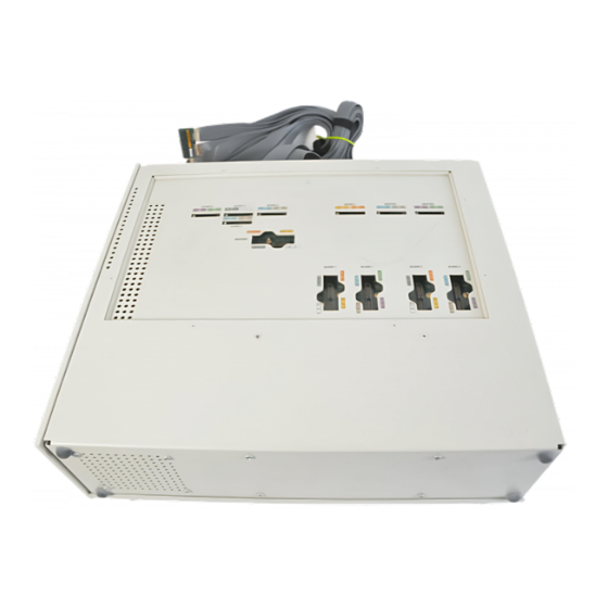
Page 41: Figure 16: Dimensions Of The Preprocessor Unit
Table 1 on page 5 (clearances are not shown in Figure 16). 474.32 mm (18.674 in) 425.45 mm (16.750 in) 420.37 mm (16.550 in) 139.70 mm 160.27 mm (5.500 in) (6.310 in) Figure 16: Dimensions of the preprocessor unit TMSSY2 mPGA479 Socket Hardware Support... - Page 42 Specifications TMSSY2 mPGA479 Socket Hardware Support...
-
Page 43: Appendix
JAPAN POWER CORD 161-0298-00 CHINA POWER CORD 161-0304-00 Requires six probes Requires five cables This support software is available only to customers with a valid, restricted, and secret nondisclosure agreement (RS-NDA) with Intel and Tektronix. TMSSY2 mPGA479 Socket Hardware Support... -
Page 44: Apply Tmscab1 Labels
2. Follow the steps in Figure 17 while attaching the labels. Align and place the labels in the label indents. Repeat for all steps. Preprocessor-unit TMSCAB1 Cable Blank Module end Match the color and the channel name. Blank Figure 17: Apply TMSCAB1 labels TMSSY2 mPGA479 Socket Hardware Support... -
Page 45: Probe Adapter Notes
System Clock Rate The TMSSY2 hardware support can acquire data from the microprocessor operating at speeds of up to 200 MHz. Contact your Tektronix sales representative for current information on the fastest devices supported. Acquisition before Reset If data is acquired before a processor Reset signal is observed by the preproces- sor unit, the data acquired by the logic analyzer will be inaccurate. - Page 46 Appendix TMSSY2 mPGA479 Socket Hardware Support...
- Page 47 20 Reset, 31 source synchronous capture, disabled, 20 Restrictions Environmental specifications, 21 address bus, 31 altitude, 22 data bus, 31 electrostatic immunity, 22 disabling the cache, 31 humidity, 22 temperature, 21 Fuses, maintenance, 11 TMSSY2 mPGA479 Socket Hardware Support...
- Page 48 TLA7AX4, probes, measurements, 2 electrical, 17 TLA7AX4 module, measurements, 3, 30 environmental, 21 TMSCAB1 cable, connections, 3, 30 mechanical (dimensions), 26, 27 TMSCAB1 Cables, appling lables, 3 Standard accessory, 29 Storage, long- - term, 13 TMSSY2 mPGA479 Socket Hardware Support...
Need help?
Do you have a question about the TMSSY2 mPGA479 and is the answer not in the manual?
Questions and answers