Table of Contents
Advertisement
Quick Links
Advertisement
Table of Contents

Related Manuals for Harman Martin VDO Dotron


Summary of Contents for Harman Martin VDO Dotron
- Page 1 VDO Dotron User Manual www.audiovias.com...
-
Page 2: Dimensions
All dimensions are in millimeters Information subject to change without notice. HARMAN Professional Denmark ApS disclaims liability for any injury, damage, direct or indirect loss, consequential or economic loss or any other loss occasioned by the use of, inability to use or reliance on the information contained in this document. - Page 3 VDO Dotron Flange Bracket Ø4.5 Ø15 Ø6.5 54 45 VDO Dotron Half-coupler Rigging Clamp Tube external Ø 48-51 VDO Dotron to VDO Sceptron End Coupler All dimensions are in millimeters Dimensions www.audiovias.com...
- Page 4 VDO Sceptron to VDO Dotron Pivot Coupler All dimensions are in millimeters VDO Dotron User Manual www.audiovias.com...
-
Page 5: Table Of Contents
Contents Dimensions ............... . 2 Safety information . -
Page 6: Safety Information
Safety information WARNING! Read the safety precautions in this section before installing, powering, operating or servicing this product. The following symbols are used to identify important safety information on the product and in this document: Warning! Warning! Warning! Warning! Warning! Safety hazard. - Page 7 PROTECTION FROM ELECTRIC SHOCK • Read and respect the directions given in the user documentation of all the devices that you intend to connect to the VDO Dotron, particularly the instructions, warnings and limits that apply to: - system layout, - connections to other devices, - specified cables, - maximum cable lengths, and...
- Page 8 Generic 48 VDC external PSU safety limits If you supply a chain of VDO Dotron dots with DC power from a 48 VDC external PSU (power supply unit) that is not manufactured by Martin®, you must not exceed the maximum power rating of the output from the PSU or 40 VDO Dotron dots, whichever limit you reach first.
-
Page 9: Introduction
Introduction Thank you for selecting a product from the Martin® VDO Dotron family. These compact LED-based display fixtures are designed to integrate into a Martin® P3 video system, where they can display video from a variety of sources. Each fixture forms one pixel in the video display. As well as video, the VDO Dotron can be controlled using a DMX lighting controller. -
Page 10: Precautions To Avoid Damage
Precautions to avoid damage Important! To obtain the best performance from the VDO Dotron and avoid causing damage that is not covered by the product warranty, make sure that everyone who is involved in installing, working on or using the VDO Dotron has read and understood the following information. Cleaning Excessive dirt buildup causes overheating and may lead to damage that is not covered by the product warranty. -
Page 11: Vdo Dotron Overview
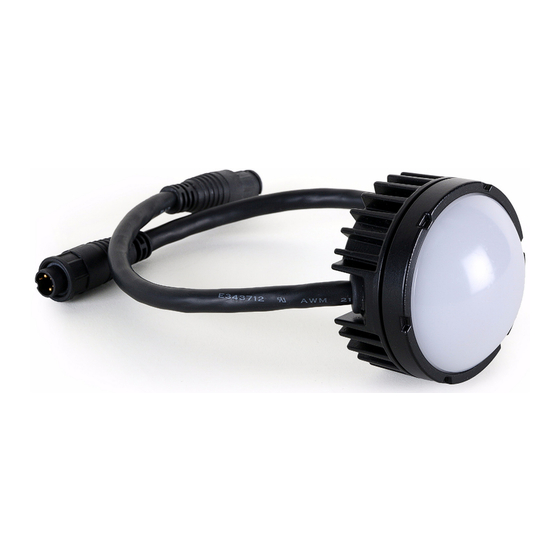
VDO Dotron overview A - DC power + data male BBD-type input C - Dot fixture connector D - Flange Bracket (optional accessory) B - DC power + data female BBD-type output (thru) connector Figure 1: Overview VDO Dotron overview www.audiovias.com... -
Page 12: Physical Installation
Physical installation Warning! Read “Safety information” on page 6 before installing the VDO Dotron and read all of this ‘Physical installation’ chapter before starting work. You can install VDO Dotron dots on a surface or structure using one of four methods: •... -
Page 13: Mounting On A Surface
Mounting on a surface Mounting on a surface using Flange Brackets The Flange Bracket available from Martin® as an optional accessory for the VDO Dotron (see “Accessories” on page 35) is a mounting plate that is recommended for installing dots on a flat surface. All fasteners must be suitable for the application and environment. -
Page 14: Mounting On A Rigging Truss
Installing directly on a surface It is also possible to install the VDO Dotron directly on a flat surface if you have access to the back of the surface. To install an VDO Dotron on a surface: 1. See Figure 3 (dimensions are in millimeters). Ø... -
Page 15: Installing With Other Martin® Creative Video Products
Installing with other Martin® creative video products VDO Dotron dots can be fastened to other Martin® creative video products using coupler brackets available from Martin® (see “Accessories” on page 35). Fastening to the end of a VDO Sceptron or VDO Fatron To fasten a VDO Dotron to the end of a VDO Sceptron or VDO Fatron fixture: 1. -
Page 16: System Installation
System installation Warning! Read “Safety information” on page 6 and “Precautions to avoid damage” on page 10 carefully before installing an VDO Dotron system. Warning! Connect the VDO Dotron only to the devices and using only the Martin® cables specified in this manual. - Page 17 connecting an unmanaged Gigabit Ethernet switch to the P3 System Controller and then connecting each P3 PowerPort directly to the switch. This eliminates the risk of one P3 PowerPort signal failing and causing loss of signal to the P3 PowerPorts daisy-chained behind it. 9.
-
Page 18: Installing A Dmx-Controlled System
Installing a DMX-controlled system In a DMX-controlled system, an RDM-compliant DMX lighting controller sends a DMX control data signal over a DMX link to the installation, and then over the hybrid link to the VDO Dotron dots. The DMX link requires DMX cable. It can be maximum 300 m (1000 ft.) in length and must run in one single daisy-chain, but it can be extended or split into branches using an RDM-compliant amplifier/splitter such as the Martin®... - Page 19 Installing a DMX system using the Martin® IP66 PSU 240W DMX/RDM Controller 48 VDC power DMX link (DMX cable) Hybrid (DC power and data) link DMX/RDM Splitter (if used) Martin® IP66 PSU 240W Martin® IP66 PSU 240W Hybrid Hybrid lead-in cable, lead-in cable, Martin®...
- Page 20 To create a DMX-controlled installation that draws DC power from the Martin® IP66 PSU 240W external power supply unit: 1. See Figure 9 on page 19 for an overview of this type of installation 2. Make sure that no devices in the installation can be connected to AC mains power until all installation work is complete.
- Page 21 Installing a DMX system using a generic external 48 VDC PSU DMX/RDM Controller 48 VDC power DMX link (DMX cable) Hybrid (DC power and data) link DMX/RDM Splitter (if used) External PSU External PSU Hybrid DC Hybrid DC lead-in cable lead-in cable Inline fuse Inline fuse...
- Page 22 Warning! If you decide to use any other external PSU than the Martin® devices listed earlier in this section, you must verify that the combination of equipment used is compliant with all applicable safety and electromagnetic compatibility regulations. To create a DMX-controlled installation that draws DC power from a generic PSU: 1.
-
Page 23: System Setup
System setup Warning! Read “Safety information” on page 6 and “Precautions to avoid damage” on page 10 before applying power to an VDO Dotron installation. Setting up for P3 display A Martin® P3 system allows video to be displayed on an installation that consists of or includes VDO Dotron dots. -
Page 24: Rdm
Using an RDM-compliant DMX controller such as Martin® M-PC, you can communicate with the VDO Dotron dots on the DMX data link via RDM. You can: • Retrieve data from dots • Set the DMX addresses of the dots and set their DMX mode •... -
Page 25: Using The Vdo Dotron
Using the VDO Dotron Warning! Read “Safety information” on page 6 and “Precautions to avoid damage” on page 10 on before applying power to the VDO Dotron. Do not use the VDO Dotron if the ambient temperature exceeds 55° C (131° F) or falls below -20° C (-4° F). Thermal regulation The VDO Dotron dot has a protective thermal shutdown feature that blacks out the dot if it exceeds its permitted maximum operating temperature. -
Page 26: Magnetic 'Control Button
Magnetic ‘control button’ A magnetic sensor is embedded inside the VDO Dotron behind the label on the back of the dot (see C in Figure 1 on page 11). The sensor acts as a control button. To activate the sensor, swipe a magnet past the side of the dot near where the input cable tail enters the dot. - Page 27 Testing, rebooting and returning to defaults The table below lists the functions of the magnetic ‘control button’ on each VDO Dotron dot. Test patterns are stored in onboard memory. This lets you test the LEDs without an external controller, but test patterns can also be called up on P3 system controllers, the P3 PowerPort 1500 and the P3 PowerPort 1000 IP.
-
Page 28: Service And Maintenance
Service and maintenance Warning! Read “Safety information” on page 6 and “Precautions to avoid damage” on page 10 before carrying out service on the VDO Dotron. Warning! Lock out AC mains power to the installation before servicing. Warning! Refer any service operation not described in this manual to a qualified service technician. Important! Excessive dirt buildup causes overheating and may damage the product. -
Page 29: Led Performance
To clean the product, use warm water and a soft brush or a low-pressure or medium-pressure water jet. Use car shampoo to help remove dirt and grease. If possible, dry with a soft cloth to avoid streaking. Do not use a stiff brush or scouring pad. -
Page 30: Troubleshooting
Troubleshooting Problem Probable cause(s) Remedy Check that system is correctly connected, set up and running. Control is lost and activating magnetic ‘control button’ causes Hold magnet over ‘control button’ until LEDs 1 - 4 Error has occurred. VDO Dotron to show constant or turn blue, then move magnet away, to reboot VDO flashing red status indication. -
Page 31: Dmx Protocols
DMX protocols RGB Mode Channel DMX Value Function 0 → 100% 0 - 255 Green 0 → 100% 0 - 255 Blue 0 → 100% 0 - 255 Table 5: DMX Protocol, RGB Mode Basic Mode Channel DMX Value Function Dimmer fade (MSB) 8-bit coarse control, closed 0% →... -
Page 32: Pre-Programmed Fx
Pre-programmed FX Select the FX in this table on channel 5 in Basic Mode. Set FX execution speed on channel 6. Synchronize and set offsets between dots on channel 7. Channel DMX Value Function No FX Intensity FX Wave Step Pulse Blackout strobe 2x strobe... - Page 33 Channel DMX Value Function Normal to inverted color in / out wave Normal to inverted color in / out step Normal to inverted color in / out pulse 90 - 100 No function (reserved for future use) Special FX Police chase Nightrider Stars Fiberoptic white...
-
Page 34: Specifications
Specifications Physical Diameter ..............72 mm (2.9 in.) Height . - Page 35 Construction Base..............Cast aluminum Color .
- Page 36 Power + Data Input Cable, 5-pin male XLR (for DMX) + 4-pin male XLR (for P3 PowerPort) to female BBD, 0.25m (9.8 in.) ....P/N 91616049 Power + Data Input Cable, 5-pin male XLR (for DMX) + male Tripix type (for Martin®...
- Page 37 FCC Compliance This device complies with Part 15 of the FCC Rules. Operation is subject to the following two conditions: (1) This device may not cause harmful interference, and (2) this device must accept any interference received, including interference that may cause undesired operation.
- Page 38 www.audiovias.com...
- Page 39 www.audiovias.com...
- Page 40 www.martin.com • Olof Palmes Allé 18 • 8200 Aarhus N • Denmark Tel: +45 8740 0000 • Fax +45 8740 0010 www.audiovias.com...
Need help?
Do you have a question about the Martin VDO Dotron and is the answer not in the manual?
Questions and answers