Table of Contents
Advertisement
Quick Links
Instruction Manual
Form 5207
April 2007
4195KA, KB, KC, and KS Series Gauge
Pressure Controllers
Contents
1. Introduction
Scope of Manual
. . . . . . . . . . . . . . . . . . . . . . . .
. . . . . . . . . . . . . . . . . . . . . . . . . . . . .
. . . . . . . . . . . . . . . . . . . . . . . . . .
. . . . . . . . . . . . . . . . . . . . .
. . . . . . . . . . . . . . . . . . . . . . . . .
. . . . . . . . . . . . . . . . . . . . . . . . . .
. . . . . . . . . . . . . . . . . . . . . .
. . . . . . . . . . . . . . . . . . . . . . . . . . . . . . . . . .
3. 4195KA Series Proportional-Only Controllers
. . . . . . . . . . . . . . . . . . . . . . . . .
. . . . . . . . . . . . . . . . . . . . . .
. . . . . . . . . . . . . . . . . . . . . . . . . .
. . . . . . . . . . . . . . . . . . . . . . . . .
. . . . . . . . . . . . . . . . . . . . .
. . . . . . . . . . . . . . . . . . . . . . . . . .
. . . . . . . . . . . . . . . . . . . . . .
. . . . . . . . . . . . . . . . . . . . . . . . . .
. . . . . . . . . . . . . . . . . . . . . . . . . .
www.Fisher.com
4195KA, KB, KC, and KS Controllers
1-3
1-4
1-4
. . . . . . . . . . . . . . . . . . . .
1-4
. . . . . . . . . . .
2-1
2-1
2-1
2-1
2-1
. . . . . . . . . . . . . . . . . . .
2-2
. . . . . . . . . . .
2-3
. . . . . . . . . . . .
2-4
. . . . . . . . . . . . . . . .
2-4
. . . . . .
2-4
2-5
.
3-1
. . . . . . . . . . . .
3-1
3-1
. .
3-1
. . . . . . . . . . . . . .
3-2
3-2
3-2
. . . . .
3-3
. . .
3-4
. . . . . . . . .
3-4
3-4
. . . . . . . . . . . .
3-6
3-6
3-7
3-7
3-8
3-8
4. 4195KB Series Proportional-Plus-Reset
Controllers and 4195KC Series
Proportional-Plus-Reset-Plus-Rate Controllers
. . . . . . . . . . . . . . . . . . . . . . . . . .
. . . . . . . . . . . . . . . . . . . . . . . . .
. . . . . . . . . . . . . . . . . . . . . .
. . . . . . . . . . . . . . . . . . . . . . .
. . . . . . . . . . . . . . . . . . . . . . . . .
. . . . . . . . . . . . . . . . . . . . . .
. . . . . . . . . . . . . . . . . . . . . . . . . .
. . . . . . . . . . . . . . . . . . . . . . . . . .
. . . . . . . . . . . . . . . . . . . . . . . . .
. . . . . . . . . . . . . . . . . . . . .
. . . . . . . . . . . . . . . . . . . . .
. . . . . . . . . . . . . . . . . . . . . . . . .
. . . . . . . . . . . . . . . . . . . . . . . . .
. . . . . . . . . . . . . . . . . . . . . . . . .
4-1
. . . . . . . . . . . .
4-1
4-1
. .
4-2
. . . . . . . . . . . . . .
4-2
4-2
4-2
4-2
4-3
. . . . . . . . . . . . . . . . .
4-3
4-4
4-4
. . . . . . . . .
4-5
4-5
. . . . . . . . . . . .
4-5
4-7
. . . .
4-9
. . . . . . . . . . . . . . . .
4-10
4-10
4-13
4-13
4-13
. . . . . . . . . .
4-13
Advertisement
Table of Contents

Related Manuals for Emerson Fisher KC Series


Summary of Contents for Emerson Fisher KC Series
-
Page 1: Table Of Contents
Instruction Manual Form 5207 4195KA, KB, KC, and KS Controllers April 2007 4195KA, KB, KC, and KS Series Gauge Pressure Controllers Contents 1. Introduction 4. 4195KB Series Proportional-Plus-Reset Scope of Manual ......Controllers and 4195KC Series Description . - Page 2 Instruction Manual Form 5207 4195KA, KB, KC, and KS Controllers April 2007 Replacing Link 2 ....6-21 Contents (continued) Replacing Link 3 .
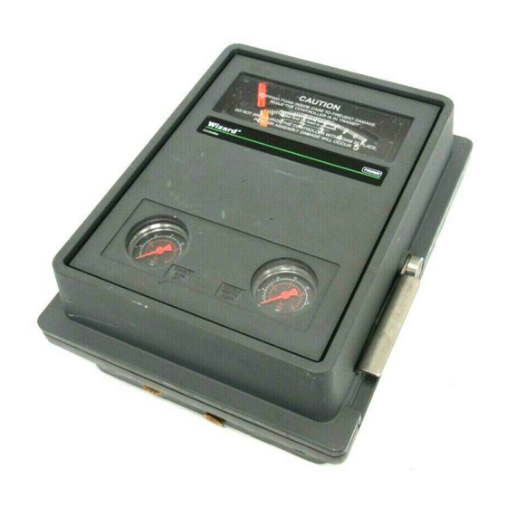
- Page 3 Instruction Manual Form 5207 4195KA, KB, KC, and KS Controllers April 2007 NAMEPLATE W5663-1 / IL W6831 / IL Figure 1-1. 4195K Series Gauge Pressure Controllers Controller Mounting Parts for Actuator Contents (continued) with Casing-Mounted Controller ..7-19 Replacing the Switch Body Assembly, Controller Mounting Parts for Actuator...
-
Page 4: Description
If you have any questions about these instructions, Emerson Process Management contact your Emerson Process Managementt sales Educational Services, Registration office before proceeding. P.O. Box 190; 301 S. 1st Ave. - Page 5 Instruction Manual Form 5207 4195KA, KB, KC, and KS Controllers April 2007 Table 1-1. Specifications Available Configurations Controller Adjustments : 5 to 500% of process See table 1-2 Proportional Band input span : Adjustable from 0.01 to more than 74 Reset Input Signal (Process Sensor Range minutes per repeat (from 100 to less than 0.0135...
- Page 6 Directives. 1. These terms are defined in ISA Standard S51.1. 2. Consult your Emerson sales office for additional information. 3. The pressure/temperature limits in this document and any applicable standard or code limitation should not be exceeded. 4. This product can be used with natural gas. Natural gas should not contain more than 20 ppm of H 5.
- Page 7 Instruction Manual Form 5207 4195KA, KB, KC, and KS Controllers April 2007 Table 1-3. Process Sensor (Capsular Element) Pressure Ratings SPAN OPERATING RANGE CAPSULE CAPSULAR OPERATING MATERIAL STANDARD RANGES LIMIT 0 to 150 mbar 100 mbar 160 mbar −350 mbar 350 mbar 510 mbar 0 to 400 mbar...
- Page 8 Instruction Manual Form 5207 4195KA, KB, KC, and KS Controllers April 2007 Table 1-4. Process Sensor (Bourdon Tube) Pressure Ratings and Materials SPAN OPERATING RANGE OPERATING STANDARD BOURDON TUBES LIMITS MATERIAL Minimum Maximum Minimum Maximum 0 to 1.6 −1 0 to 2.5 −1 0 to 4 −1...
-
Page 9: Installation
Instruction Manual Form 5207 4195KA, KB, KC, and KS Controllers April 2007 Section 2 TYPE 657 ACTUATOR Installation TYPE 4195K CONTROLLER WARNING To avoid personal injury or property damage resulting from the sudden release of pressure: D Always wear protective clothing, gloves, and eyewear when performing any installation operations. -
Page 10: Pressure Connections
Instruction Manual Form 5207 4195KA, KB, KC, and KS Controllers April 2007 HEX HEAD CAP SCREW (KEY 66) REGULATOR HEX HEAD LOCKWASHER CAP SCREW (KEY 67) (KEY 362) HEX NUT BRACKET (KEY 364) (KEY 68) LOCKWASHER (KEY 363) PIPE CLAMP ELBOW (KEY 69) (KEY 365) -
Page 11: Process Pressure Connection
Instruction Manual Form 5207 4195KA, KB, KC, and KS Controllers April 2007 (3.29) (6.35) (2.49) LOCK WASHER (KEY 67) TOP VIEW HEX HEAD TOP VIEW CAP SCREW LOCKWASHER (KEY 66) (0.50) (KEY 67) BRACKET (KEY 68) (10.25) (2.43) HEX HEAD CAP SCREW ROUND (KEY 66) -
Page 12: Supply Pressure Connection
40 microns in diameter will suffice in REAR VIEW FRONT VIEW most applications, check with an 1/4-18 NPT Emerson Process Management field 1/4-18 NPT CONTROLLER OUTPUT SUPPLY PRESSURE office and industry instrument air CONNECTION CONNECTION... -
Page 13: Vent
Instruction Manual Form 5207 4195KA, KB, KC, and KS Controllers April 2007 Vent CAUTION WARNING When installing a remote vent pipe, Personal injury or property damage take care not to over-tighten the pipe could result from fire or explosion of in the vent connection. - Page 14 Instruction Manual Form 5207 4195KA, KB, KC, and KS Controllers April 2007...
-
Page 15: Adjustments For 4195Ka Series Controllers
Instruction Manual Form 5207 4195KA, KB, KC, and KS Controllers April 2007 METAL BALL SWITCHING ZONE INDICATOR LOADER KNOB AUTO/MANUAL SWITCH W3679 / IL SET POINT AUTO/MANUAL STATION INDICATOR (SUFFIX LETTER E) PROCESS POINTER PROPORTIONAL BAND ADJUSTMENT PROPORTIONAL BAND INDICATOR COVER OUTPUT PRESSURE GAUGE W6832 / IL... -
Page 16: Changing Controller Action
Instruction Manual Form 5207 4195KA, KB, KC, and KS Controllers April 2007 D For reverse control action: An increasing sensed vacuum decreases output pressure. After changing the action, tighten the screws on the proportional band indicator cover. Switching The Auto/Manual Station (suffix letter E) Note Switching the controller between... -
Page 17: Startup For 4195Ka Series Controllers
Instruction Manual Form 5207 4195KA, KB, KC, and KS Controllers April 2007 Note Note If the controller has the auto/manual When performing the startup station (suffix letter E), be sure the procedures, keep in mind that the initial settings are guidelines. They controller is in the automatic mode before performing the prestartup will vary depending on the actual... -
Page 18: Calibration Of 4195Ka Series Controllers
Instruction Manual Form 5207 4195KA, KB, KC, and KS Controllers April 2007 Calibration of 4195KA Series readjustment of the process pointer zero adjustment. Controllers 1. Remove the two screws (key 6) and lift off the proportional band indicator cover (key 36). WARNING 2. - Page 19 Instruction Manual Form 5207 4195KA, KB, KC, and KS Controllers April 2007 POINTER ZERO ADJUSTMENT POINTER ZERO ADJUSTMENT LOCKING SCREW REMOTE SET POINT ZERO ADJUSTMENT (SUFFIX LETTER M) REMOTE SET POINT PROCESS POINTER ZERO ADJUSTMENT SPAN ADJUSTMENT LOCKING SCREW (SUFFIX LETTER M) W6832 / IL FRONT VIEW SCREW 1...
-
Page 20: Remote Set Point (Suffix Letter M) Zero And Span Calibration
Instruction Manual Form 5207 4195KA, KB, KC, and KS Controllers April 2007 12. If necessary, perform the process indicator zero Remote Set Point (suffix letter M) Zero and span calibration procedure in this section. and Span Calibration Otherwise, perform the flapper alignment procedure Refer to figures 3-1 and 3-3 for adjustment in this section. -
Page 21: Principle Of Operation For 4195Ka Series Controllers
Instruction Manual Form 5207 4195KA, KB, KC, and KS Controllers April 2007 SET POINT INDICATOR RESET BELLOWS (VENTED) REVERSE ACTION QUADRANT PROPORTIONAL BELLOWS PROPORTIONAL BAND ADJUSTMENT FEEDBACK PROCESS POINTER LINK REMOTE SET POINT CONNECTED HERE FEEDBACK INPUT ELEMENT MOTION FLAPPER PIVOT CONNECTED HERE DIRECT ACTION QUADRANT... -
Page 22: Remote Set Point (Suffix Letter M) Operation
Instruction Manual Form 5207 4195KA, KB, KC, and KS Controllers April 2007 MANUAL LOADER AUTOMATIC POSITION AUTO/MANUAL SWITCH MANUAL LOADER KNOB PLASTIC TUBE OUTPUT PRESSURE TO FINAL CONTROL METAL BALL ELEMENT MANUAL RELAY POSITION AUTO/MANUAL SWITCH SUPPLY PRESSURE OUTPUT PRESSURE TO FINAL CONTROL RELAY OUTPUT PRESSURE ELEMENT... -
Page 23: Adjustments For 4195Kb And Kc Series
Instruction Manual Form 5207 4195KA, KB, KC, and KS Controllers April 2007 METAL BALL SWITCHING ZONE INDICATOR LOADER KNOB AUTO/MANUAL SWITCH SET POINT INDICATOR W3679 / IL PROCESS POINTER AUTO/MANUAL STATION (SUFFIX LETTER E) PROPORTIONAL BAND ADJUSTMENT ANTI-RESET WINDUP DIFFERENTIAL RELIEF VALVE (SUFFIX LETTER F) RATE ADJUSTMENT... -
Page 24: Proportional Band Adjustment (Pb Adj)
Instruction Manual Form 5207 4195KA, KB, KC, and KS Controllers April 2007 Capsular Element Controllers for Vacuum Pressure D For direct control action: An increasing sensed vacuum increases output pressure. D For reverse control action: An increasing sensed vacuum decreases output pressure. -
Page 25: Switching The Auto/Manual Station
Instruction Manual Form 5207 4195KA, KB, KC, and KS Controllers April 2007 Switching the Auto/Manual Station controller output connection to the external feedback connection (see (suffix letter E) figure 2-5). Adjust the controller for full output pressure and with the RESET knob adjusted to 0.01 Note minutes/repeat, verify the tubing... -
Page 26: Startup For 4195Kb And Kc Series Controllers
Instruction Manual Form 5207 4195KA, KB, KC, and KS Controllers April 2007 Tuning proportional action: Create a load upset Startup for 4195KB and KC Series by momentarily changing the set point. Check for Controllers system cycling. If the system does not cycle, lower Perform the prestartup checks and, if necessary, the proportional band setting (thus raising the gain) calibrate the controller prior to this procedure. -
Page 27: General Calibration Instructions
Instruction Manual Form 5207 4195KA, KB, KC, and KS Controllers April 2007 adjustment screw. Tighten the zero adjustment General Calibration Instructions locking screw. 5. Apply process pressure equal to the process Note scale span upper limit. If the controller has the auto/manual 6. - Page 28 Instruction Manual Form 5207 4195KA, KB, KC, and KS Controllers April 2007 POINTER ZERO ADJUSTMENT POINTER ZERO ADJUSTMENT LOCKING SCREW PROCESS POINTER SPAN ADJUSTMENT ANTI-RESET WINDUP RELIEF VALVE (SUFFIX LETTER F) ANTI-RESET WINDUP VALVE ADJUSTING SCREW (SUFFIX LETTER F) W6833 / IL REMOTE SET POINT REMOTE SET POINT RESET...
-
Page 29: Flapper Alignment
Instruction Manual Form 5207 4195KA, KB, KC, and KS Controllers April 2007 2. Set the proportional band between DIRECT and zero and span calibration procedure REVERSE. before the flapper alignment. Flapper leveling screw numbers and adjustments 3. Apply remote set point pressure equal to the are shown in figure 4-3. - Page 30 Instruction Manual Form 5207 4195KA, KB, KC, and KS Controllers April 2007 the controller has a capsular input element, note the hole where link number 1 is connected to the input element, then disconnect link 1. This method should only be used if pressure is not available to pressure the input element to the mid-scale value.
-
Page 31: Anti-Reset Windup (Suffix Letter F) Differential Relief Valve Calibration
Instruction Manual Form 5207 4195KA, KB, KC, and KS Controllers April 2007 aligned. This may occur because the output was not 6. Provide a regulated supply pressure to the sufficiently stabilized in steps 9 through 13. Repeat controller. Do not exceed the normal operating steps 8 through 19. -
Page 32: Principle Of Operation For 4195Kb And Kc Series Controllers
Instruction Manual Form 5207 4195KA, KB, KC, and KS Controllers April 2007 changing the controller set point. After each change Calibration for the differential relief valve to in controller process pressure or set point, the relieve on falling controller output pressure controller output pressure should quickly change and 1. - Page 33 Instruction Manual Form 5207 4195KA, KB, KC, and KS Controllers April 2007 SET POINT RESET BELLOWS REVERSE ACTION INDICATOR QUADRANT PROPORTIONAL PROPORTIONAL BELLOWS BAND ADJUSTMENT FEEDBACK PROCESS POINTER LINK REMOTE SET POINT CONNECTED HERE FEEDBACK MOTION INPUT ELEMENT FLAPPER CONNECTED HERE PIVOT DIRECT ACTION QUADRANT...
- Page 34 Instruction Manual Form 5207 4195KA, KB, KC, and KS Controllers April 2007 SET POINT REVERSE ACTION RESET BELLOWS INDICATOR QUADRANT PROPORTIONAL BELLOWS PROPORTIONAL BAND ADJUSTMENT FEEDBACK LINK PROCESS POINTER REMOTE SET POINT CONNECTED HERE FEEDBACK FLAPPER MOTION INPUT ELEMENT PIVOT CONNECTED HERE DIRECT ACTION QUADRANT...
-
Page 35: Anti-Reset Windup (Suffix Letter F) Operation
Instruction Manual Form 5207 4195KA, KB, KC, and KS Controllers April 2007 and contraction of the capsule moves the set point RELAY OUTPUT indicator via connecting linkage. Increasing the PRESSURE control pressure to the capsule increases the set point setting and decreasing the control pressure RESET RATE VALVE... - Page 36 Instruction Manual Form 5207 4195KA, KB, KC, and KS Controllers April 2007 MANUAL LOADER AUTOMATIC POSITION AUTO/MANUAL SWITCH MANUAL LOADER KNOB PLASTIC TUBE OUTPUT PRESSURE TO FINAL CONTROL METAL BALL ELEMENT MANUAL RELAY POSITION AUTO/MANUAL SWITCH SUPPLY PRESSURE OUTPUT PRESSURE TO FINAL CONTROL RELAY OUTPUT PRESSURE ELEMENT...
-
Page 37: Remote Set Point (Option M)
Instruction Manual Form 5207 4195KA, KB, KC, and KS Controllers April 2007 the set point. Increase the pressure to increase the Section 5 set point, and decrease the pressure to decrease 4195KS Series Differential Gap the set point. Controllers Proportional Band (Differential Gap) Operating Information The proportional band knob adjusts width of the gap between switching points. -
Page 38: Prestartup Checks
Instruction Manual Form 5207 4195KA, KB, KC, and KS Controllers April 2007 SET POINT ADJUSTMENT PROCESS PROCESS INDICATOR INDICATOR PROPORTIONAL BAND INDICATOR COVER TIE BAR PROPORTIONAL BAND ADJUSTMENT LINK 5 LINK 1 LONG PIVOT BOURDON ASSEMBLY TUBE CONNECTING INDICATOR LINK ZERO INDICATOR ADJUSTMENT... -
Page 39: Process Zero And Span Adjustment
Instruction Manual Form 5207 4195KA, KB, KC, and KS Controllers April 2007 SCREW 1 SCREW 2 SCREW 3 PROCESS SPAN ADJUSTMENT REMOTE SET POINT SPAN ADJUSTMENT SIDE VIEW OF SET POINT/PROCESS INDICATOR ASSEMBLY SIDE VIEW OF CONTROLLER SHOWING FLAPPER LEVELING SCREWS C0528-1/IL Figure 5-1. -
Page 40: Remote Set Point Zero And Span (Option M)
Instruction Manual Form 5207 4195KA, KB, KC, and KS Controllers April 2007 GUIDE MOUNTING FLEXURE SCREW DRIVE FLEXURE ADJUSTMENT LINK A SCREW LOWER TRAVEL STOP PIVOT ASSEMBLY A UPPER TRAVEL LINK B STOP LINEARITY ADJUSTMENT PIVOT ASSEMBLY B MOUNTING SCREW TIE BAR CAPSULES REMOTE SET POINT ZERO ADJUSTMENT SCREW... -
Page 41: Setting Switching Points
Instruction Manual Form 5207 4195KA, KB, KC, and KS Controllers April 2007 Setting Switching Points Direct-Acting Controllers The controller output signal will switch from zero pressure to full supply pressure when increasing process pressure passes the upper switching point. The controller output signal will not return to zero pressure until decreasing process pressure passes the lower switching point. - Page 42 Instruction Manual Form 5207 4195KA, KB, KC, and KS Controllers April 2007 SET POINT POSITIVE FEEDBACK REVERSE ACTION INDICATOR BELLOWS QUADRANT PROPORTIONAL BELLOWS PROPORTIONAL (VENTED) BAND ADJUSTMENT FEEDBACK PROCESS POINTER LINK REMOTE SET POINT CONNECTED HERE FEEDBACK MOTION INPUT ELEMENT FLAPPER CONNECTED HERE PIVOT...
-
Page 43: Principle Of Operation
Instruction Manual Form 5207 4195KA, KB, KC, and KS Controllers April 2007 MANUAL LOADER AUTOMATIC POSITION AUTO/MANUAL SWITCH MANUAL LOADER KNOB PLASTIC TUBE OUTPUT PRESSURE TO FINAL CONTROL METAL BALL ELEMENT MANUAL RELAY POSITION AUTO/MANUAL SWITCH SUPPLY PRESSURE OUTPUT PRESSURE TO FINAL CONTROL RELAY OUTPUT PRESSURE ELEMENT... -
Page 44: Remote Set Point (Option M)
Instruction Manual Form 5207 4195KA, KB, KC, and KS Controllers April 2007 between the two switching points by moving the tube and to the auto/manual switch. Output pressure position of the upper switching point. from the relay registers on the other side of the plastic tube as well as in the auto/manual switch. -
Page 45: Maintenance
Instruction Manual Form 5207 4195KA, KB, KC, and KS Controllers April 2007 Section 6 measures that must be taken to protect against process media. Maintenance Controller parts are subject to normal wear and must Note be inspected and replaced as necessary. The frequency of inspection and parts replacement Unless otherwise noted, key numbers depends upon the severity of the service conditions. - Page 46 Instruction Manual Form 5207 4195KA, KB, KC, and KS Controllers April 2007 Table 6-1. Troubleshooting Chart Fault Possible Cause Check Correction 1. Process wanders or cycles 1.1 Proportional band and reset 1.1 Refer to the startup procedures 1.1 If stable control cannot be about set point settings for controller settings...
- Page 47 Instruction Manual Form 5207 4195KA, KB, KC, and KS Controllers April 2007 Table 6-1. Troubleshooting Chart (continued) Fault Possible Cause Check Correction 2. Controlling off set point as 2.7 Reset valve leaks 2.7 Hold the input constant and 2.7 Replace the reset valve reflected by process and set point adjust the output to 1.0 bar (15 (4195KB Series) or the rate/reset...
- Page 48 Instruction Manual Form 5207 4195KA, KB, KC, and KS Controllers April 2007 Table 6-1. Troubleshooting Chart (continued) Fault Possible Cause Check Correction 6. Controller will not attain full 6.5 Nozzle pressure leak 6.5 Check for nozzle tubing leaks 6.5 Tighten the relay nozzle tubing output range (continued) with a water bottle and soap nut (key 18).
-
Page 49: Replacing The Process Pressure Scale
Instruction Manual Form 5207 4195KA, KB, KC, and KS Controllers April 2007 CLEAN-OUT WIRE EXHAUST PORT (NO O-RING USED) O-RINGS (KEY 15) O-RING (KEY 13) W3440 / IL DEFLECT LOWER PORTION OF THE SLOT RELAY RELAY MOUNTING SCREWS W5744 / IL (KEY 10) Figure 6-2. -
Page 50: Replacing The Relay
Instruction Manual Form 5207 4195KA, KB, KC, and KS Controllers April 2007 4. Position the controller assembly in the Replacing the Relay replacement case and cover. WARNING 5. Start the nine mounting screws, but do not tighten. Refer to the Maintenance WARNING 6. -
Page 51: Replacing The Supply Gauge, Proportional
Instruction Manual Form 5207 4195KA, KB, KC, and KS Controllers April 2007 Replacing the Supply Gauge, Disassembly Proportional, Reset, Reset Valve, and 1. Remove the controller assembly from the case Positive Feedback Tubing Assemblies by performing steps 1 through 3 of the case and cover replacement procedure. - Page 52 Instruction Manual Form 5207 4195KA, KB, KC, and KS Controllers April 2007 RELAY NOZZLE TUBING PLASTIC WASHER ASSEMBLY WASHER (KEY 20) (KEY 18) SCREW (KEY 19) E-RING (KEY 27) RETAINING CLIP (KEY 26) O-RING PROPORTIONAL BAND ADJUSTMENT (KEY 25) ADJUSTABLE PLASTIC SET POINT WASHER...
- Page 53 Instruction Manual Form 5207 4195KA, KB, KC, and KS Controllers April 2007 Assembly 1. Apply a suitable lubricant, such as key 318 or equivalent, to the set point beam assembly; then position a plastic washer (key 22) and the proportional band adjustment knob (key 25) on the HOLE set point beam assembly (key 23) as shown in figure 6-3.
- Page 54 Instruction Manual Form 5207 4195KA, KB, KC, and KS Controllers April 2007 LOCKING ADJUSTABLE SET POINT PIVOT ASSEMBLY SCREW AND WASHER SCREW AND WASHER (KEYS 19 AND 20) (KEYS 19 AND 20) NOTES: SCREW INSERTED INTO THE ADJUSTABLE SET POINT PIVOT ASSEMBLY. SCREW INSERTED INTO THE RELAY NOZZLE TUBING ASSEMBLY.
-
Page 55: Replacing The Flapper Assembly And Flapper Flexure Pivot Assembly
Instruction Manual Form 5207 4195KA, KB, KC, and KS Controllers April 2007 24. Disconnect link 1 from the input element, noting 32. Mount the controller as described in the the hole from which it is removed, for capsular input Installation section. elements, and tape the process pointer to the lower 33. -
Page 56: Bellows
Instruction Manual Form 5207 4195KA, KB, KC, and KS Controllers April 2007 PROPORTIONAL BELLOWS BELLOWS BRACKET (KEY 31) ADJUSTABLE SET POINT PIVOT ASSEMBLY (KEY 17) SCREW AND WASHER (KEYS 19 AND 20) LINK 4 LINK 2 W4199 / IL Figure 6-7. Bellows Assembly and Proportional Band Adjustment (Process Scale and Proportional Band Indicator Cover Removed) 13. - Page 57 Instruction Manual Form 5207 4195KA, KB, KC, and KS Controllers April 2007 LINK 4 LINK 4 ADJUSTMENT FLEXURE PIVOT FLAPPER ASSEMBLY FOUR SCREWS ASSEMBLY (KEY 9) (KEY 10) AND LINK 4 W4198 / IL Figure 6-9. Exploded View of Flexure Pivot Assembly LINK 2 LINK 3 LINK 2 ADJUSTMENT...
- Page 58 Instruction Manual Form 5207 4195KA, KB, KC, and KS Controllers April 2007 LEVELING SCREW NUMBER 1 CONNECTING TAB ON FLAPPER ASSEMBLY 1/2 OF PIN W4191 / IL DIAMETER W3451 / IL Figure 6-11. Link 2 Adjustment 28. Insert the pivot of the adjustable set point pivot 33.
- Page 59 Instruction Manual Form 5207 4195KA, KB, KC, and KS Controllers April 2007 supply pressure. If not, adjust flapper leveling screw in figure 6-3, and move the set point beam shoe 1 (the screw nearest the nozzle) until the output is (key 29) slightly toward the center of the flapper within 0.14 bar (2 psig) of supply pressure.
- Page 60 Instruction Manual Form 5207 4195KA, KB, KC, and KS Controllers April 2007 8. Unscrew the bellows assembly (key 48). If the FOUR SCREWS (KEY 6) bellows assembly cannot be removed by hand, thread a machine screw (key 35) into the bellows until tight;...
-
Page 61: Replacing The Reset Restriction Valve (4195Kb Series)
Instruction Manual Form 5207 4195KA, KB, KC, and KS Controllers April 2007 32. If ±1 percent of process scale span cannot be Note achieved by adjusting the gain screw (key 34), loosen the machine screw (key 35) attaching the The following procedure (steps 21 reset bellows and slide it to the left if the reading in through 32) adjusts the reset gain of step 26 is greater than in step 25, or to the right if... -
Page 62: Replacing The Rate/Reset Valve Assembly (4195Kc Series)
Instruction Manual Form 5207 4195KA, KB, KC, and KS Controllers April 2007 8. Set the reset adjustment to 0.01 minutes per 7. While holding the rate/reset valve assembly, repeat. remove the machine screw (key 162) from the frame. 9. Apply the proper supply pressure to the controller, cap the nozzle and check for leaks. -
Page 63: Replacing The Anti-Reset Windup (Suffix Letter F) Differential Relief Valve
Instruction Manual Form 5207 4195KA, KB, KC, and KS Controllers April 2007 Replacing the Anti-Reset Windup (suffix LINK 4 ADJUSTMENT COURSE ZERO ADJUSTMENT letter F) Differential Relief Valve LINK 1 LINK 4 WARNING Refer to the Maintenance WARNING on page 6-1. Refer to the 4195KB or 4195KC Series suffix letter F portion of figure 7-1 for key number locations. -
Page 64: Bourdon Tube Controller Maintenance And Calibration
Instruction Manual Form 5207 4195KA, KB, KC, and KS Controllers April 2007 7. Connect link 1 to the Bourdon tube. 8. With the process pressure at 0 percent, the process pointer should indicate 0 percent on the process scale. If not, loosen the two screws on link 1 and adjust the length of link 1 to position the process pointer at 0 percent. - Page 65 Instruction Manual Form 5207 4195KA, KB, KC, and KS Controllers April 2007 ALIGNED ZERO ADJUSTMENT MISALIGNED FINE ZERO W3443-1 / IL LOCKING SCREW ADJUSTMENT W3475-1 / IL Figure 6-15. Process Pointer Alignment even after full span adjustment, move the link to the 7.
- Page 66 Instruction Manual Form 5207 4195KA, KB, KC, and KS Controllers April 2007 screw 1 (the screw nearest the nozzle) until CLINCH FLAPPER LEVELING clearance is obtained. SCREW 6. Disconnect link 1 from the Bourdon tube and manually position the process pointer to the process scale upper limit.
-
Page 67: Bourdon Tube Travel Stop Installation And Adjustment
Instruction Manual Form 5207 4195KA, KB, KC, and KS Controllers April 2007 14. Perform the controller calibration procedures LINK 4 ADJUSTMENT BELLOWS BRACKET and, if necessary, the appropriate remote set point SCREW HEADS (KEY 31) calibration procedure in Section 3, 4, or 5. Bourdon Tube Travel Stop Installation and Adjustment WARNING... -
Page 68: Bourdon Tube Controller Calibration: Zero And Span Adjustment
Instruction Manual Form 5207 4195KA, KB, KC, and KS Controllers April 2007 6. Adjust the lower travel stop adjustment (shown in LOWER TRAVEL STOP ADJUSTMENT LOCK NUT figure 6-18) until it touches the Bourdon tube. MOUNTING SCREW (KEY 76) 7. Tighten the lower travel stop adjustment lock nut. 8. - Page 69 Instruction Manual Form 5207 4195KA, KB, KC, and KS Controllers April 2007 POINTER ZERO ADJUSTMENT POINTER ZERO ADJUSTMENT LOCKING SCREW PROCESS POINTER SPAN ADJUSTMENT ANTI-RESET WINDUP RELIEF VALVE ANTI-RESET WINDUP VALVE ADJUSTING SCREW RATE ADJUSTMENT RESET REMOTE SET POINT REMOTE SET POINT RESET ADJUSTMENT W3599-1 / IL...
- Page 70 Instruction Manual Form 5207 4195KA, KB, KC, and KS Controllers April 2007 5. For a controller with manual set point, move the screw is adjusted to its limit and the span is still too set point indicator to the mid-scale mark on the short or too long, proceed with step 14.
-
Page 71: Capsular Element Controller Maintenance And Calibration
Instruction Manual Form 5207 4195KA, KB, KC, and KS Controllers April 2007 10. Perform the capsular element maintenance Capsular Element Controller calibration procedure in this section. Perform the Maintenance and Calibration controller calibration procedures and, if necessary, the appropriate remote set point calibration Replacing the Capsular Element procedure in Section 3, 4, or 5. -
Page 72: Replacing The Short Pivot Assembly
Instruction Manual Form 5207 4195KA, KB, KC, and KS Controllers April 2007 10. Connect the left-hand end of link 5 (key 88) to the pivot adjustment arm in the hole position noted in step 3. BEARING END BUSHING 11. Replace the tie bar (key 97). 12. -
Page 73: Replacing The Process Tubing
Instruction Manual Form 5207 4195KA, KB, KC, and KS Controllers April 2007 LINK 5 LINK 1 LINK 4 LINK 4 ADJUSTMENT W4769 / IL LINK 3 LINEARITY LINK 2 ADJUSTMENT SCREW LINK 3 ADJUSTMENT LINK 2 ADJUSTMENT Figure 6-21. Capsular Element Controller Link Locations and Adjustments Note Replacing Capsular Element Controller Links... - Page 74 Instruction Manual Form 5207 4195KA, KB, KC, and KS Controllers April 2007 pointer with the process pointer subassembly. Replacing Capsular Element Controller Link 1 Tighten the zero adjustment locking screw. 1. Remove the two screws (key 6), and lift off the 5.
- Page 75 Instruction Manual Form 5207 4195KA, KB, KC, and KS Controllers April 2007 9. Adjust the proportional band to 5 percent the nozzle) until the output is within 0.14 bar (2 psig) REVERSE. Turn flapper leveling screw 1 (the screw of supply pressure. nearest the nozzle) until the nozzle just touches the 8.
-
Page 76: Capsular Element Controller Maintenance Calibration
Instruction Manual Form 5207 4195KA, KB, KC, and KS Controllers April 2007 link 5, and move the process pointer to the mid-scale mark of the process scale span. Tighten TRAVEL the screw. STOP 8. Perform the controller calibration procedures and, if necessary, the appropriate remote set point calibration procedure in Section 3, 4, or 5. - Page 77 Instruction Manual Form 5207 4195KA, KB, KC, and KS Controllers April 2007 D For positive or compound pressure with a Aligning the Capsular Element Linkage three-capsule stack, loosen the machine screws 1. Adjust the process pressure to 75 percent of the (key 139) that secure the travel stop (key 83) to the capsular element range.
-
Page 78: Capsular Element Controller
Instruction Manual Form 5207 4195KA, KB, KC, and KS Controllers April 2007 8. The process pointer should indicate mid-scale ±3 Capsular Element Controller Zero and Span percent of the process scale span. If not, loosen the Adjustment screw on either link 1 or link 5 and adjust the length so that the process pointer points to the mid-scale mark on the process scale. - Page 79 Instruction Manual Form 5207 4195KA, KB, KC, and KS Controllers April 2007 GUIDE FLEXURE MOUNTING SCREW DRIVE FLEXURE ADJUSTMENT LINK A SCREW LOWER TRAVEL STOP PIVOT ASSEMBLY A UPPER TRAVEL LINK B STOP LINEARITY ADJUSTMENT PIVOT ASSEMBLY B MOUNTING SCREW TIE BAR CAPSULES REMOTE SET POINT ZERO ADJUSTMENT SCREW...
-
Page 80: Remote Set Point (Suffix Letter M)
Instruction Manual Form 5207 4195KA, KB, KC, and KS Controllers April 2007 18. Adjust the process pressure to the lower and CAUTION upper limits of the scale span to make sure the process pointer is still within ±1 percent of the lower and upper scale limits. -
Page 81: Replacing Pivot Assembly B (Key 115)
Instruction Manual Form 5207 4195KA, KB, KC, and KS Controllers April 2007 3. Note where link A is connected. Disconnect link Before tightening the drive flexure screws, hold the A (key 116) from the lever arm on pivot assembly A pivot assembly shaft in the middle of the bushing (key 114). -
Page 82: Replacing The Remote Set Point Tubing
Instruction Manual Form 5207 4195KA, KB, KC, and KS Controllers April 2007 2. Loosen the screw in the replacement link A and Note adjust the length to match the link being replaced. Tighten the screw. See figure 6-20. The adjustment arm of the remote set point pivot assembly A 3. -
Page 83: Aligning The Flexures
Instruction Manual Form 5207 4195KA, KB, KC, and KS Controllers April 2007 Aligning the Flexures Setting the Travel Stops WARNING WARNING Refer to the Maintenance WARNING Refer to the Maintenance WARNING on page 6-1. on page 6-1. 1. Loosen the set screw (key 87) in the travel stop 1. -
Page 84: Remote Set Point Zero And Span Adjustment
Instruction Manual Form 5207 4195KA, KB, KC, and KS Controllers April 2007 5. Replace the tie bar (key 106) and install the two 6. To increase the span, proceed as follows: screws (key 103). a. Turn the remote set point span adjustment screw clockwise. -
Page 85: Remote Set Point Linearity Adjustment
Instruction Manual Form 5207 4195KA, KB, KC, and KS Controllers April 2007 Remote Set Point Linearity Adjustment Auto/Manual Station (suffix letter E) Maintenance Replacing the Auto/Manual Station WARNING WARNING Refer to the Maintenance WARNING on page 6-1. Refer to the Maintenance WARNING Refer to figures 7-1 and 7-7 for key number on page 6-1. -
Page 86: Replacing The Switch Body Assembly
Instruction Manual Form 5207 4195KA, KB, KC, and KS Controllers April 2007 3. Using a 1/16-inch (1.5 mm) punch, push the CAUTION groove pin (key 303) out toward the surface of the lever cover plate. 4. Remove the switch lever (key 304), lever spring In the next step, take care to tighten (key 302), and lever spring seat (key 301). -
Page 87: Replacing The Loader Range Spring, Diaphragm Assembly, Ball Seat, Tubing, And Ball
Instruction Manual Form 5207 4195KA, KB, KC, and KS Controllers April 2007 Note arrow) to relieve pressure on the spring. In the following step, the ends of the springs must be in the counterbored 3. Loosen the four screws (key 289), and separate spring seats before compression. -
Page 88: Replacing The Loader Valve Plug And Valve Plug Spring
Instruction Manual Form 5207 4195KA, KB, KC, and KS Controllers April 2007 5. Install the valve plug spring and valve plug. Replacing the Loader Valve Plug and Valve Plug Spring 6. Tighten the spring seat screw. WARNING 7. Temporarily apply supply pressure and process pressure and check for leaks. -
Page 89: Parts
Use of components not part of (as in part of another assembly) supplied by Emerson will void your plated (as in plated steel) warranty, might adversely affect the point (as in set point) performance of the instrument, and... - Page 90 Instruction Manual Form 5207 4195KA, KB, KC, and KS Controllers April 2007 Description Part Number Description Part Number O-Ring, nitrile Proportional tubing ass’y, SST Used between frame and case at conns: process pressure, For 4195KA or KB Series 28A0766X022 either 1/4-18 NPT internal or 1/2-14 NPT external; output For 4195KC Series 27A3217X022 and supply;...
- Page 91 Instruction Manual Form 5207 4195KA, KB, KC, and KS Controllers April 2007 Description Part Number Description Part Number Bellows ass’y (2 req’d) Brass 16A6953X012 Process and set pt indicator ass’y w/sensing element 16A6953X022 Bellows beam, A96061 (aluminum) The part numbers in the Key 56 tables are for the complete 0.2 to 1.0 bar (3 to 15 psig) 16A6957X012 process and set pt indicator ass’y with a process sensing...
- Page 92 Instruction Manual Form 5207 4195KA, KB, KC, and KS Controllers April 2007 Description Part Number Description Part Number Remote set pt ass’y (suffix letter M) Pressure control block, CF8M (316 SST Casting) 1/4-18 NPT Internal Process Connection The part numbers listed for key 62 are for the complete remote 1 req’d for all types w/o remote set pt and set point (suffix letter M) ass’y.
- Page 93 Instruction Manual Form 5207 4195KA, KB, KC, and KS Controllers April 2007 Key 61 Process Scale, Positive Pressure Key 61 Process Scale, Vacuum and Compound Pressure Scale Range Part Number SCALE RANGE PART NUMBER 0 to 150 mbar 1R0003X1562 0 to 400 mbar 1R0003X0422 Vacuum Pressure 0 to 0.6...
- Page 94 Instruction Manual Form 5207 4195KA, KB, KC, and KS Controllers April 2007 SEE VIEW L SEE VIEW H SEE VIEW G SECTION B-B SEE VIEW M SEE VIEW E SECTION D-D VIEW C-C 4195KA SERIES VIEW C-C 4195KS SERIES APPLY LUB/ SEALANT 56A9752-U SHT 1 and 2 / DOC Figure 7-1.
- Page 95 Instruction Manual Form 5207 4195KA, KB, KC, and KS Controllers April 2007 VIEW F-F VIEW F-F 56A9752-U SHT 4 / DOC VIEW K-K PROCESS CONNECTION ADAPTORS VIEW E VIEW E 4195KB SERIES 4195KB SERIES WITH ANTI-RESET WINDUP (SUFFIX LETTER F) VIEW C-C VIEW C-C 4195KB SERIES...
- Page 96 Instruction Manual Form 5207 4195KA, KB, KC, and KS Controllers April 2007 VIEW F-F VIEW F-F VIEW E 4195KC SERIES WITH ANTI-RESET WINDUP (SUFFIX LETTER F) VIEW E 4195KC SERIES VIEW C-C 4195KC SERIES WITH VIEW C-C 4195KC SERIES ANTI-RESET WINDUP (SUFFIX LETTER F) 56A9752-U SHT 3 / DOC Figure 7-1.
- Page 97 Instruction Manual Form 5207 4195KA, KB, KC, and KS Controllers April 2007 56A9752-U SHT 2 / DOC 56A9752-U SHT 3 / DOC 56A9752-U SHT 2 / DOC SECTION B-B SECTION B-B SECTION B-B VIEW B-B 4195KA SERIES 4195KB SERIES 4195KC SERIES 4195KS SERIES 56A9752-U SHT 4 / DOC VIEW L...
- Page 98 Instruction Manual Form 5207 4195KA, KB, KC, and KS Controllers April 2007 56A9752-U SHT 4 / DOC VIEW H VIEW G CONTROLLERS WITH REMOTE SET POINT BOURDON TUBE (SUFFIX LETTER M) TRAVEL STOPS 56A9752-U SHT 5 / DOC 56A9752-U SHT 3 / DOC VIEW M VIEW M EXTERNAL FEEDBACK FOR...
-
Page 99: Process And Set Point Indicator Assembly
Instruction Manual Form 5207 4195KA, KB, KC, and KS Controllers April 2007 32B1532-A / DOC Figure 7-2. Process and Set Point Indicator Assembly for Bourdon Tube Controllers Description Part Number Process and Set Point Indicator Assembly (key 56) (figures 7-2 and 7-3) Machine screw, fill hd, 18−8 SST Description Part Number... - Page 100 Instruction Manual Form 5207 4195KA, KB, KC, and KS Controllers April 2007 36A6986-C / DOC Figure 7-3. Process and Set Point Indicator Assembly for Capsular Element Controllers (Positive and Compound Pressure Shown) 7-12...
- Page 101 58A0708X222 1. For information on scale compatibility, consult your Emerson Process Management sales office. Capsular Element Assembly may be ordered as part of the Process/Setpoint Indicator Assembly (key 56) or ordered separately. See Capsular Element Assembly section for available replacement parts.
-
Page 102: Indicator Assembly
Instruction Manual Form 5207 4195KA, KB, KC, and KS Controllers April 2007 39A1126-H / DOC Figure 7-4. Indicator Assembly Indicator Assembly (key 101) (figure 7-4) Description Part Number Set pt indicator ass’y, A93003 (aluminum) For controllers w/remote set pt 31B2241X012 Description Part Number For controllers w/o remote set pt... - Page 103 Instruction Manual Form 5207 4195KA, KB, KC, and KS Controllers April 2007 VIEW A-A VIEW A-A VIEW A-A VIEW A-A 58A0708-E/DOC 58A0710-C / DOC POSITIVE AND COMPOUND VACUUM PRESSURE Figure 7-5. Capsular Element Assembly Description Part Number Description Part Number Machine screw, fill hd, 18−8 SST Connecting link ass’y, For mounting the short pivot clevix ass’y...
-
Page 104: Remote Set Point Assembly
Instruction Manual Form 5207 4195KA, KB, KC, and KS Controllers April 2007 Key 80 Capsular Element Assembly, Travel Stop (key 86) and Diaphragm Assembly Extension CAPSULAR ELEMENT MATERIAL N09902 Capsular Number of Diaphragm RANGE Element Travel Stops Assembly (key 80) (key 86) Extension Part Number... -
Page 105: Auto/Manual Station (Suffix Letter E)
Instruction Manual Form 5207 4195KA, KB, KC, and KS Controllers April 2007 APPLY LUB / SEALANT 36A6988-C / DOC Figure 7-6. Remote Set Point Assembly Description Part Number Auto/Manual Station (suffix letter E) Mounting plate, G10100 (pl steel) 38A0668X012 (figure 7-7) Spring washer, pl steel 17A2700X012 Lower loader ass’y, aluminum... - Page 106 Instruction Manual Form 5207 4195KA, KB, KC, and KS Controllers April 2007 SECTION A-A SECTION B-B SECTION C-C APPLY LUB / SEALANT 48A2905-A / DOC Figure 7-7. Auto/Manual Station Assembly Description Part Number Description Part Number Ball, SST (2 req’d) 1J1550X0012 Lever ass’y, SST 18A2866X012...
-
Page 107: Controller Mounting Parts
Controller Mounting Parts for Actuator With Yoke- Mounted Controller (figure 2-1) Note Spacer spool, steel (3 req’d) 1C559024092 Contact your Emerson Process Management sales Cap screw, hex hd, pl steel office for any additional parts required for controller (3 req’d) 1B762424052 mounting. -
Page 108: Fittings
1B884618992 Fisher is a mark owned by Fisher Controls International LLC, a member of the Emerson Process Management business division of Emerson Electric Co. Emerson Process Management, Emerson, and the Emerson logo are trademarks and service marks of Emerson Electric Co. All other marks are the property of their respective owners.
Need help?
Do you have a question about the Fisher KC Series and is the answer not in the manual?
Questions and answers