Table of Contents
Advertisement
Instruction Manual
Form 589
February 2016
Type 99 Pressure Reducing Regulator
WARNINg
!
Since a pilot-operated regulator is
constructed of both a pilot and a main
valve, care should be used not to exceed
the maximum inlet pressure shown on
the nameplate of either unit. When inlet
pressure exceeds the pilot limitation, a
pilot supply reducing regulator and/or
relief valve is required.
WARNINg
!
Failure to follow these instructions or
to properly install and maintain this
equipment could result in an explosion
and/or fi re causing property damage and
personal injury or death.
Fisher
regulators must be installed,
®
operated and maintained in accordance
with federal, state and local codes, rules
and regulations and Emerson Process
Management Regulator Technologies,
Inc. instructions.
If the regulator vents gas or a leak
develops in the system, service to the unit
may be required. Failure to correct trouble
could result in a hazardous condition.
Call a gas service person to service the
unit. Only a qualifi ed person must install
or service the regulator.
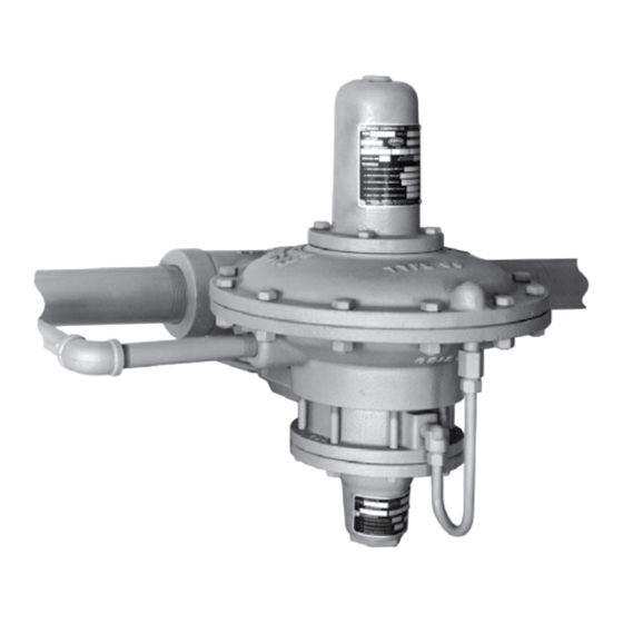
W2676
Figure 1. Type 99 Regulator with Type 61H (High Pressure) Pilot
Introduction
Scope of the Manual
This manual describes and provides instructions for
Installation, startup, adjustment and parts ordering
information of Type 99 pressure reducing regulator
complete with standard P590 Series integral fi lter.
Information on other equipment used with this
regulator can be found in separate manuals.
www.fisherregulators.com
Type 99
Advertisement
Table of Contents

Related Manuals for Emerson Fisher Type 99


Summary of Contents for Emerson Fisher Type 99
- Page 1 ® operated and maintained in accordance Introduction with federal, state and local codes, rules and regulations and Emerson Process Management Regulator Technologies, Scope of the Manual Inc. instructions. This manual describes and provides instructions for If the regulator vents gas or a leak...
- Page 2 Type 99 Specifications Specifications and ratings for various Type 99 constructions are listed in the Specifications section below. Some specifications for a given regulator as it originally comes from the factory are stamped on the nameplates located on the pilot and actuator spring cases. An additional nameplate may be installed on the pilot to indicate a regulator with O-ring stem seal.
- Page 3 Type 99 BLEED vALvE OuTLET PIPE BLEED ORIFICE MAIN vALvE SPRINg MAIN DIAPHRAgM PuSHER POST PILOT ASSEMBLy ORIFICE PILOT DIAPHRAgM ASSEMBLy INLET PILOT DIAPHRAgM A6814 INLET PRESSuRE OuTLET PRESSuRE PILOT CONTROL SPRINg ATMOSPHERIC PRESSuRE LOADINg PRESSuRE Figure 2. Schematic of Type 99 Regulator with Type 61L (Low Pressure) Pilot Principle of Operation The key to the operation of a Type 99 regulator is the In operation, assume the outlet pressure is less than...
- Page 4 Type 99 MAIN vALvE DOWNSTREAM SPRINg CONTROL LINE RELIEF BLEED vALvE ORIFICE BLEED vALvE MAIN DIAPHRAgM RELIEF vALvE DIAPHRAgM BODy yOKE ORIFICE yOKE PuSHER POST INLET ASSEMBLy PRESSuRE TuBINg CONNECTION RELAy yOKE FLANgE vALvE ADAPTOR PILOT DIAPHRAgM 54A2767-a A2505 INLET PRESSuRE PILOT SPRINg OuTLET PRESSuRE ATMOSPHERIC PRESSuRE...
- Page 5 Type 99 DISTRIBuTION PRESSuRE CONTROL LINE INTERMEDIATE PRESSuRE CONTROL LINE TyPE 161AyW MONITORINg PILOT (ALSO REPRESENTATIvE OF TyPE 627-109) WORKINg MONITOR PILOT PILOT SuPPLy LINE LOADINg INTERMEDIATE PRESSuRE PRESSuRE WORKINg OPTIONAL WORKINg REguLATOR PILOT SuPPLy MONITOR REguLATOR REguLATOR OPTIONAL PILOT SuPPLy DISTRIBuTION uPSTREAM REguLATOR...
- Page 6 Type 99 Table 3. Maximum Allowable Pressure Drop and Minimum Differential Pressures MAIN vALvE SPRINg MINIMuM MAXIMuM DIFFERENTIAL MAXIMuM ALLOWABLE PRESSuRE FOR FuLL ORIFICE SIZE (1)(5) Wire Diameter Free Length DISK MATERIAL PRESSuRE DROP Part STROKE Number psig psig 1C277127022 0.148 3.76 6.00...
- Page 7 Type 99 Table 5. Working Monitor Performance MONITORINg PILOT INFORMATION MINIMuM PRESSuRE Pilot Spring AT WHICH WORKINg Spring Range MONITOR REguLATOR Construction Wire Diameter Free Length CAN BE SET Part Number psig 3 in. w.c. / 7 mbar 3 to 12 in. w.c. 7 to 30 mbar 1B653927022 0.105...
- Page 8 Type 99 Clean out all pipelines before installation and check A Type 99 regulator has two 1/2 NPT control line to be sure the regulator has not been damaged or pressure taps on opposite sides of the lower casing collected foreign material during shipping. (key 29, Figure 9).
- Page 9 Type 99 the extra high-pressure pilot of 1000 psig / 69.0 bar The only adjustment on the regulator is the reduced maximum inlet pressure in case the Type 1301F supply pressure setting affected by the pilot control spring regulator fails open, this protection is insufficient if the (key 43, Figure 9, 12, 14 or 18).
- Page 10 Type 99 On reassembly of the regulator, it is recommended Inspect the diaphragm (key 11) and pusher post that a pipe thread sealant be applied to pressure gasket (key 7). Either part must be replaced if it is connections and fittings as indicated in Figures 7 damaged or no longer pliable.
- Page 11 Type 99 diaphragm plate (key 10), pusher post assembly 5. Unscrew the bleed orifice (key 52, Figure 11) from (key 8) and diaphragm rod (key 4) must be mounted the yoke (key 37). Also to be removed with the on the ball of the lever (key 9) so that the pusher bleed orifice are the relay disk assembly (key 48) post (key 8) orientation is as shown in Figure 9.
- Page 12 Type 99 Converting the Pilot 4. Unscrew the diaphragm nut (key 128) and remove a diaphragm plate (key 41A), diaphragm (key 40) Note and another diaphragm plate (key 41B). A complete pilot assembly rather than 5. Unscrew the eight cap screws (key 47) and individual parts may be ordered for remove the pilot body (key 39) and gasket the following conversion procedure.
- Page 13 Type 99 20A7146-B Figure 6. Travel Indicator Assembly Parts Ordering 2. Loosen the union nut (key 14, Figure 9) and remove the lower casing (key 29) with the cap A serial number is assigned to each regulator, and it screw (key 22) or disk and holder assembly is stamped on both the actuator and pilot nameplates.
- Page 14 Type 99 20A7148-B 10A7145 APPLy SEALANT (S) / LuBRICANT (L) Figure 7. O-ring Stem Seal Figure 8. O-ring Sealed Handwheel Travel Indicator Assembly (Figure 6) Description Part Number Description Part Number Main Spring (continued) Complete Assembly (includes individual parts 50 psid / 3.4 bar d maximum allowable listed below) 20A7146X0C2 pressure drop...
- Page 15 Type 99 CONTROL LINE TAP (OTHER TAP 180° OPPOSITE) 1/4 IN. / 6.4 mm VENT SHOWN 90° COUNTERCLOCKWISE FROM NORMAL DJ6642 COMPLETE REguLATOR SHOWINg TyPE 61L PILOT AND DISK SEAT AS – APPLy ANTI-SEIZE COMPOuND PTS – APPLy PIPE THREAD SEALANT APPLy LuBRICANT (L) Figure 9.
- Page 16 Type 99 A.S. A.S. A.S. - APPLy ANTI-SEIZE COMPOuND Figure 10. O-ring Seat Detail for Type 99 Regulator with Type 61L (Low Pressure) or 61H (High Pressure) A.S. DJ6642_B A.S. - APPLy ANTI-SEIZE COMPOuND PTS - APPLy PIPE THREAD SEALANT Figure 11.
- Page 17 Type 99 A.S. 30A6800 A.S. - APPLy ANTI-SEIZE COMPOuND PTS - APPLy PIPE THREAD SEALANT Figure 12. Pilot Relay Assembly for Type 99 Regulator with Type 61H (High Pressure) Pilot Parts A.S. C0289-1C PILOT RELAy AND COvER ASSEMBLy A.S. - APPLy ANTI-SEIZE COMPOuND PTS - APPLy PIPE THREAD SEALANT Figure 13.
- Page 18 Type 99 L. S. A. S. L. S. L. S. 30A6923_D A.S. – APPLy ANTI-SEIZE COMPOuND L.S. – APPLy LEAD SEAL COMPOuND Figure 14. Pilot Relay Assembly for Type 99 Regulator with Type 61L (Low Pressure) Pilot Parts LOCTITE GRADE “A” 10A7151_A Figure 15.
- Page 19 Type 99 Actuator and Main Body Assembly (Figures 7, 9 and 17) (continued) Description Part Number Disk Holder Disk seat Brass 1B884314012 316 Stainless steel 1B884335072 O-ring Seat 7/8 in. / 22 mm orifi ce Brass 1E603214012 316 Stainless steel 1E603235072 1-1/8 in.
- Page 20 Type 99 TYPE 1301F PILOT SUPPLY REGULATOR TYPE H110 POP RELIEF VALVE A6803 Figure 17. 1000 psig / 69.0 bar Maximum Inlet Regulator Partial Detail Actuator and Main Body Assembly Standard P590 Series Filter Assembly (Figures 7, 9 and 17) (continued) (Figure 16) Description Part Number...
- Page 21 Type 99 Pilot and Tubing Parts Low or Description Part Number High-Pressure Pilot (Figures 8, 10, 11, 12, Closing Cap Low-pressure pilot 13, 14 and 15) For use with standard low-pressure pilot, Plastic T11069X0012 For use with standard low-pressure pilot, Steel 1E422724092 Description Part Number...
- Page 22 Type 99 A.S. 54A1905 A.S. – APPLy ANTI-SEIZE COMPOuND Figure 18. Type 61HP (Extra High Pressure) Pilot...
- Page 23 Type 99 Pilot and Tubing Parts Low or Description Part Number High-Pressure Pilot (Figures 8, 10, 11, Spring Case, Cast iron Standard 2P969419012 12, 13, 14 and 15) (continued) Adjusting Screw, Plated steel Standard 1C216032992 Cap Screw, Plated steel (8 required) 1B787724052 Description Part Number...
- Page 24 For further information visit www.fisherregulators.com The Emerson logo is a trademark and service mark of Emerson Electric Co. All other marks are the property of their prospective owners. Fisher is a mark owned by Fisher Controls International LLC, a business of Emerson Process Management.
Need help?
Do you have a question about the Fisher Type 99 and is the answer not in the manual?
Questions and answers