Advertisement
Instruction Manual
D100331X012
Fisherr 1066 and 1066SR Piston Rotary
Actuators with Style F and G Mounting
Adaptations
Contents
. . . . . . . . . . . . . . . . . . . . . . . . . . . . . . . . . . .
. . . . . . . . . . . . . . . . . . . . . . . . . . . . .
. . . . . . . . . . . . . . . . . . . . . . . . . . . . . . . . .
. . . . . . . . . . . . . . . . . . . . . . . . . . . . . . .
. . . . . . . . . . . . . . . . . . . . . . . . .
. . . . . . . . . . . . . . . . . . . . . . . . . . . . . . . . . . . .
. . . . . . . . . . . . . . . . . . . . . . . . . .
. . . . . . . . . . . . . . . . . . . . . . . . . . . . . . . . .
. . . . . . . . . . . . . . . . . . . . . . . . .
. . . . . . . . . . . . . . . . . . . . . . . . . . . . . . . . . .
. . . . . . . . . . . . . . . . . . . . . . . . . . . . . . . .
Assembly
. . . . . . . . . . . . . . . . . . . . . . . . . . . . . . . . . .
. . . . . . . . . . . . . . . . . . . . . . . . . . . . . . .
. . . . . . . . . . . . . . . . . . . . . . . . . . . . . . . . . . . . .
. . . . . . . . . . . . . . . . . . . . . . . . . . . . . . . . . . . . .
Introduction
Scope of Manual
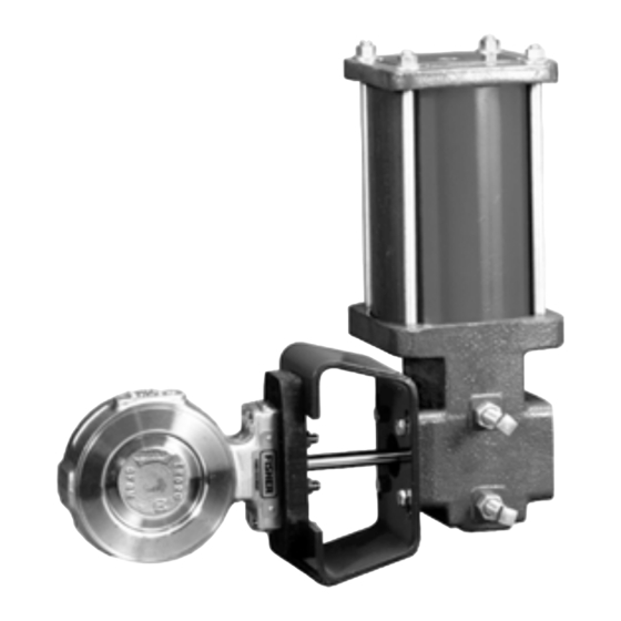
This instruction manual provides installation, operation, maintenance, and parts ordering information for Fisher 1066
and 1066SR piston rotary actuators (see figure 1). Instructions for the control valve and accessories are covered in
separate manuals.
Do not install, operate, or maintain 1066 and 1066SR actuators without being fully trained and qualified in valve,
actuator, and accessory installation, operation, and maintenance. To avoid personal injury or property damage, it is
important to carefully read, understand, and follow all the contents of this manual, including all safety cautions and
warnings. If you have any questions about these instructions, contact your Emerson Process Management sales office
before proceeding.
www.Fisher.com
1
1
3
2
3
4
4
. . . . . . . . . . . . . . . . . .
7
7
8
8
9
10
13
13
14
1066 and 1066SR F & G Actuators
Figure 1. Typical Actuator Assemblies
W6058-1
1066 ACTUATOR WITH FISHER 3710 POSITIONER
W6264-1
1066SR ACTUATOR WITH FISHER 8560 VALVE
October 2012
Advertisement
Table of Contents

Related Manuals for Emerson Fisher 1066


Summary of Contents for Emerson Fisher 1066
-
Page 1: Table Of Contents
To avoid personal injury or property damage, it is important to carefully read, understand, and follow all the contents of this manual, including all safety cautions and warnings. If you have any questions about these instructions, contact your Emerson Process Management sales office before proceeding. - Page 2 1. Pressure/temperature limits in this manual and any applicable code or standard must not be exceeded. 2. Actuator torque available depends on specific construction and cylinder pressure. For information on torque requirements of the valve being considered, contact your Emerson Process...
-
Page 3: Description
Educational Services For information on available courses for 1066 and 1066SR Style F and G actuators, as well as a variety of other products, contact: Emerson Process Management Educational Services, Registration P.O. Box 190; 301 S. 1 Ave. -
Page 4: Installation
Instruction Manual 1066 and 1066SR F & G Actuators October 2012 D100331X012 Installation When an actuator and valve are shipped together, the actuator is normally mounted on the valve. Follow the valve instruction manual when installing the control valve in the pipeline. If it is necessary to mount the actuator on the valve, or if it is necessary to change actuator mounting positions, perform the Actuator Mounting procedure. - Page 5 Instruction Manual 1066 and 1066SR F & G Actuators D100331X012 October 2012 Figure 2. Mounting Positions VALVE SERIES OR DESIGN VALVE SERIES OR DESIGN ACTUATOR BALL/PLUG DISC/BALL ACTION V150, V200 & CV500, 8532, 8560 MOUNTING V250 V250 ROTATION TO ROTATION TO V300 V500 &...
- Page 6 Instruction Manual 1066 and 1066SR F & G Actuators October 2012 D100331X012 1. Isolate the control valve from the line pressure, release pressure from both sides of the valve body, and drain the process media from both sides of the valve. Also, shut off all pressure lines, and release all pressure to the actuator. Use lock-out procedures to be sure that the above measures stay in effect while you work on the equipment.
-
Page 7: Loading Pressure Connection
Instruction Manual 1066 and 1066SR F & G Actuators D100331X012 October 2012 8. Perform the Adjustment procedures before applying actuator loading pressure. Loading Pressure Connection The actuator should have either a loading solenoid, a switching valve, or a positioner connected to the 1/4 NPT pressure connections located at the top of the actuator cylinder. -
Page 8: Principle Of Operation
Instruction Manual 1066 and 1066SR F & G Actuators October 2012 D100331X012 If rotation of either set screw seems difficult, apply lithium grease lubricant (key 35) to the threads of each set screw as shown in figures 5 and 6. Figure 3. -
Page 9: Disassembly
Instruction Manual 1066 and 1066SR F & G Actuators D100331X012 October 2012 D Always wear protective gloves, clothing, and eyewear when performing any maintenance operations to avoid personal injury. D Disconnect any actuator operating lines providing air pressure, electric power, or a control signal to the actuator. Be sure the actuator spring compression cannot suddenly open or close the valve. - Page 10 Instruction Manual 1066 and 1066SR F & G Actuators October 2012 D100331X012 WARNING For 1066SR Only: Avoid personal injury from the sudden release of spring pre-compression by carefully following step 5 below. 5. 1066SR Only: Loosen the cap screw (key 19) a few turns, but do not fully disengage the cap screw threads from the piston rod at this time.
- Page 11 Instruction Manual 1066 and 1066SR F & G Actuators D100331X012 October 2012 Figure 4. Fisher 1066 Assembly Detail TOP LOADING PRESSURE CONNECTION CYLINDER PISTON COVER O-RING (KEY 3) (KEY 2) (KEY 17) PISTON (KEY 5) CYLINDER (KEY 8) HOUSING (KEY 1) LOCKNUT LEVER &...
- Page 12 Instruction Manual 1066 and 1066SR F & G Actuators October 2012 D100331X012 Figure 5. Fisher 1066SR Assembly Detail LOADING PRESSURE CONNECTION PISTON (KEY 3) O-RING CYLINDER (KEY 17) COVER (KEY 2) PISTON (KEY 5) CYLINDER (KEY 8) SPRING (KEY 7) HOUSING LOCK NUT (KEY 1)
-
Page 13: Parts Ordering
October 2012 Parts Ordering When corresponding with your Emerson Process Management sales office about this equipment, refer to the serial number found on the actuator nameplate (key 27, figures 6 and 7). Also, specify the complete 11-character part number from the following parts list when ordering replacement parts. -
Page 14: Parts List
Cap Screw, pl steel (a maximum of 8 req'd for any construction) Part numbers are shown for recommended spares only. For part Travel Indicator Scale, SST numbers not shown, contact your Emerson Process Management sales Travel Indicator, SST office. Flat Washer, pl carbon steel... - Page 15 Instruction Manual 1066 and 1066SR F & G Actuators D100331X012 October 2012 Figure 6. Typical Fisher 1066 Actuator Assembly j APPLY LUB NOTE: KEY 23 IS REQUIRED FOR SIZE 20 ACTUATORS ONLY 48A4468-C...
- Page 16 Responsibility for proper selection, use, and maintenance of any product remains solely with the purchaser and end user. Fisher, Vee-Ball, FIELDVUE, and TopWorx are marks owned by one of the companies in the Emerson Process Management business unit of Emerson Electric Co.
Need help?
Do you have a question about the Fisher 1066 and is the answer not in the manual?
Questions and answers