Table of Contents
Advertisement
Quick Links
Download this manual
See also:
Installation Manual
Advertisement
Table of Contents

Related Manuals for Nibe AMB 30


Summary of Contents for Nibe AMB 30
- Page 1 MOS GB 1341-4 INSTALLATION AND MAINTENANCE INSTRUCTIONS AMB 30 AMB 30 031533 Accessory, F1330...
-
Page 3: Table Of Contents
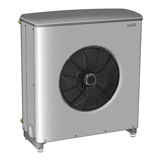
F1330 Technical specifications AMB 30 docked (hybrid operation) to NIBE F1330 Component positions Several AMB 30 docked (outdoor air operation) to several NIBE F1330 Sound pressure levels Several AMB 30 docked (hybrid operation) to several NIBE Dimensions and setting-out coordinates... - Page 4 Maintenance Instruction. AMB 30 is a heat absorbing air module that is an accessory for NIBE F1330. Outdoor air is used as a heat source. AMB 30 is a Swedish-made quality product offering a long life span and reliable operation.
-
Page 5: For The User
System description Principle of operation Outdoor air operation AMB 30 is a heat absorbing air module that is an accessory During outdoor air operation AMB 30 only uses the out- for NIBE F1330. AMB 30 is connected to F1330 only (out-... - Page 6 AMB 30 and ground/rock collector (hy- brid operation). At these temperatures the heat pump can use both the ground/rock collector and AMB 30 to supply the energy as long as the ambient temperature is suffi- ciently much warmer than the brine temperature. This operating mode increases the unit’s efficiency and uses...
-
Page 7: The Control Unit
The display mode shows the temperatures that are read off from the different temperature sensors that are con- nected to AMB 30. The [-] and [+] buttons are used to scroll through the dif- ferent units (if several are connected). -
Page 8: Maintenance Routines General
Check through the cold part of the year to make sure that there isn't a build up of ice or frost under AMB 30. The condens- ation water trough is available for management and re- moval of condensation. -
Page 9: For The Installer
The distance between AMB 30 and the house wall must If AMB 30 is replaced, the installation must be inspected be at least 400 mm. Clearance in front of AMB 30 should again. be at least one metre. AMB 30 must not be placed so For outdoor air systems (not hybrid systems) NIBE F1330 that recirculation of the outdoor air can occur. -
Page 10: Pipe Connections
Pipe installation must be carried out in accordance with All outdoor brine lines must be insulated against current norms and directives. condensation. Because AMB 30 is not equipped with shut off valves, drain valve and vent valve these must be installed to facilitate any future servicing. NOTE... -
Page 11: Dimensioning Of Pressure Expansion Vessel
(XL6) brine in DN40 cu 42 stallation of hybrid operation or outdoor air operation the (XL7) brine out DN40 cu 42 pressure expansion vessel must be dimensioned according to the following diagram. 800 1000 1200 1400 1600 1800 2000 AMB 30... -
Page 12: Connecting The Hose To Condensation Water Trough
Route the pipe downward from AMB 30. Insulate the pipe (at least 19 mm of insulation) all the way outside. Fix the drainage hose to the connection under AMB 30 (recommended dimension 32 mm) with hose clamps. NOTE Hose with heating cable for draining the condensa- tion water trough is not included. -
Page 13: Docking General
For the Installer Docking Docking General Symbol key AMB 30 can be installed in several different ways. The re- Symbol Meaning quisite safety equipment must be installed in accordance with current regulations for all docked options. Venting valve See www.nibe.eu for more docking options. -
Page 14: Abbreviations
QM60 - QM64 Venting valve QN10 Reversing valve, Heating/hot water QN21 Reversing valve, Hybrid operation QN22 Reversing valve, Outdoor air QN51 - QN53 Reversing valve, defrosting in the event of several AMB 30, connected as QN20 in the wiring diagram AMB 30... -
Page 15: Amb 30 Docked (Outdoor Air Operation) To Nibe F1330
For the Installer Docking AMB 30 docked (outdoor air operation) to NIBE F1330 -FL2 -CM4 -EB1 -EB100-BT25 -GP10 -QM40 -QM41 -RN16 -RM5 -EB100-BT1 -EP40-EP17 -EP40-GP5 -RN15 -QM32 -QN10 -AA25 -CP1 -EB100 -AA25-BT28 -EP100 -QM60 -RN10 -EP40 -RM10 -BT27 -QM64 -EB2... -
Page 16: Several Amb 30 Docked (Outdoor Air Operation) To Several Nibe F1330
For the Installer Docking Several AMB 30 docked (outdoor air operation) to several NIBE F1330 AMB 30... -
Page 17: Several Amb 30 Docked (Hybrid Operation) To Several Nibe F1330
For the Installer Docking Several AMB 30 docked (hybrid operation) to several NIBE F1330 AMB 30... -
Page 18: Electrical Connections
NOTE The live external control must be taken into consider- ation when connecting. NOTE The heat pump must not be powered when installing AMB 30. Cover removal and routing the power cable AMB 30... -
Page 19: General
The cables for heavy current and the signal cables should be routed from the side at the folded part of the side panel on the left-hand side of AMB 30. Power supply is routed through the cable grommet UB1, power supply for... -
Page 20: Connection Of Ambient Sensor (Bt28)
Electrical connections Connecting several AMB 30 Connection of ambient sensor (BT28) Up to 9 x AMB 30 can be connected to the same installa- The ambient sensor (BT28) is located in a shaded location tion. near the air intake for the AMB 30. -
Page 21: Connecting The Temperature Sensor For Brine In To The Heat Pump During Hybrid Operation (Bt26)
QN22 NOTE BT26 is only connected to the main unit (on installa- AA6-X4 tion of several AMB 30) and is only connected on in- stallations with hybrid operation. NOTE QN21 and QN22 are only connected to the main unit (with installation of several AMB 30) and only connec- Connecting the circulation pump for the ted during installations with hybrid operation. -
Page 22: Connecting The Control Unit, Bcu 30 (Aa25)
-COM1 on the relay card (AA6) as illustrated. Suitable cable type is for example LiYY 4x0.50 or similar. NOTE The control unit is only connected to the main unit (on installation of several AMB 30). Control unit,BCU 30 AMB 30 COM1... -
Page 23: Connection, Compressor Blocking In Nibe F1330 When Defrosting
Connection to F1330 with two AMB 30 when defrosting Terminal block X6:1 and X6:3 on the relay card (AA6) in AMB 30 (master unit) are connected to F1330 to X4:1 and For NIBE F1330 to know that the compressors must be X4:2 (compressor A). -
Page 24: Connecting Low Pressure Switch To Nibe F1330 (Non-Hybrid System)
For the Installer Electrical connections 2. Use the top clamps provided (AMB 30) to connect the Connecting low pressure switch to NIBE F1330 incoming cables with the cables for the upper low (non-hybrid system) pressure switch (LP2, see image). When installing with NIBE F1330 the low pressure switch 3. -
Page 25: Commissioning And Adjusting Preparations
Adjustment, charge flow 6. Go into menu "BT28 min." (in the sub menu When installing with several AMB 30 the brine flow is ad- "Stop air mode" to menu "Settings" in service mode) justed so that it is evenly divided between the units with and change the preset value to -12. -
Page 26: Sensor Placement Temperature Sensor Data
1.246 0.293 1.061 0.252 BT28 Temperature sensor, ambient 0.908 0.217 BT21 Temperature sensor, extract air 0.779 0.187 BT26 Temperature sensor, brine, collector in to the heat 0.672 0.163 pump during hybrid operation BT27 Temperature sensor, brine, collector out AMB 30... -
Page 27: Control General
[-]. Service Description System type In this menu you can choose what type of system AMB 30 has been docked to. Settings Installation specific settings can be made in this menu. Test manually... - Page 28 [-]. Diff 1,2,3.. Set what difference the differential set Service Settings in the menu "Start" must have between System type different AMB 30 (if several are installed) Defrost Settings Stop air mode for start and stop. Test manually Hybrid Language Setting range: 0.0 –...
- Page 29 BT28 max Here you can set at what ambient tem- between active and passive defrosting. perature the fan in AMB 30 and the compressor in NIBE F1330 must stop Passive defrosting starts at the set tem- because of too warm outdoor air.
- Page 30 Fan low Settings Fan high Test manually Air only Here you select at what ambient temper- QN20 (K12) Compr. ature (BT28) AMB 30 must shift from/to Heater GP5 (K11) exclusively outdoor air during hybrid operation. GP2 (K10) QN21 (K13) QN22 (K14)
- Page 31 (QN21) should be open (on) or closed (off). Setting range: on/off QN22 (K14) Here you set whether the reversing valve for rock/ground collector operation (QN22) should be open (on) or closed (off). Setting range: on/off AMB 30...
-
Page 32: Connecting Several Amb
Communication No communication between display Operation of AMB 30 and com- The alarm resets automatically when and AMB 30 (master unit of several pressor in NIBE F1330 is stopped. the communication is resumed. connected) for more than 3 minutes. The alarm may be due to a cable breakage, fault in the relay card or fault in the display unit. -
Page 33: Electrical Circuit Diagram
Miscellaneous Electrical circuit diagram Electrical circuit diagram AMB 30... -
Page 34: Electrical Circuit Diagram
Miscellaneous Electrical circuit diagram AMB 30... -
Page 35: Electrical Circuit Diagram
Miscellaneous Electrical circuit diagram AMB 30... -
Page 36: Technical Specifications Component Positions
Miscellaneous Technical specifications Technical specifications Component positions EP12 BT21 BT27 AA6-F1 UB2-4 UB5-7 EB12 EB11 AMB 30... - Page 37 UB2-4 Cable grommet, circulation pumps and reversing valves UB5-7 Cable grommet, communication cables Terminal block, incoming supply, neutral and earth Connection, brine in Connection, brine out Designations in component locations according to stand- ard IEC 81346-1 and 81346-2. AMB 30...
-
Page 38: Sound Pressure Levels
The sound pressure levels are further affected by walls, Sound pressure levels bricks, differences in ground level, etc and should therefore AMB 30 is usually placed next to a house wall, which gives only be seen as guide values. a directed sound distribution that should be considered. -
Page 39: Dimensions And Setting-Out Coordinates
Miscellaneous Technical specifications Dimensions and setting-out coordinates Ø700 Elintag Cable gland 1095 1175 Ø 30 1205 Fritt utrymme Serviceutrymme Min. avstånd vid användning av flera AMB30 Fritt utrymme framför AMB 30... -
Page 40: Technical Specifications
17.7/9.3/1.9 23.5/11.6/2.0 34/18.0/1.9 Hybrid system together with F1330 See technical data in the heat pump "Installation and maintenance instructions". Miscellaneous AMB 30 Operating voltage 400 V 3NAC 50Hz Brine, outdoor air operation only Ethylene glycol (40%) Brine, hybrid operation Ethylene glycol (40%) or Ethanol (28%) - Page 41 Working range AMB 30 outdoor air operation (not hybrid) AMB 30 together with NIBE F1330 22 kW AMB 30 together with NIBE F1330 30 - 60 kW Pressure drop AMB 30 outdoor air operation (not hybrid) at ethylene glycol 40% volume percent AMB 30...
-
Page 42: Enclosed Kit
2 x Top clamps Accessories Auxiliary relay HR 10 It requires 2 x reversing valves (NIBE SVH 40/50/65) to use AMB 30 in hybrid operation. The size is determined by the size of the output requirement. SVH 40 Part no.: 067 106 DN 40 (22 –... -
Page 43: Dealing With Malfunctions Checking The Status
Wait until the outdoor temperature is higher NOTE than the set stop value (menu "Low BT28"). As AMB 30 can be connected to a large number of Cause: Outdoor temperature hotter than 50 °C. Indic- external units, these should also be checked. - Page 44 AMB 30...
- Page 45 AMB 30...
- Page 46 AMB 30...
- Page 48 Puh: 09-274 697 0 Fax: 09-274 697 40 E-mail: info@nibe.fi www.nibe.fi AIT France, 10 rue des Moines, 67500 Haguenau Tel : 03 88 06 24 10 Fax : 03 88 06 90 15 E-mail: info@nibe.fr www.nibe.fr NIBE Energy Systems Ltd, 3C Broom Business Park, Bridge Way, Chesterfield S41 9QG Tel: 0845 095 1200 Fax: 0845 095 1201 E-mail: info@nibe.co.uk www.nibe.co.uk...
Need help?
Do you have a question about the AMB 30 and is the answer not in the manual?
Questions and answers