
Related Manuals for Nibe BA-SVM 10-200


Summary of Contents for Nibe BA-SVM 10-200
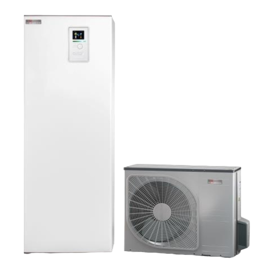
- Page 1 03-03-2021 SERVICE MANUAL Indoor module for air to water split systems NIBE BA-SVM 10-200 21-01-2019...
-
Page 3: Table Of Contents
Heating ______________________________ 20 __________________ Addition _____________________________ 22 Electrical circuit diagram __________________ 77 Dimensions and pipe connections ___________ 86 5 Current circuit Technical data _________________________ 87 __________________ Load monitor __________________________ 40 10 Item Register _________________ Item register __________________________ 89 NIBE BA-SVM 10-200... -
Page 4: Important Information
This appliance can be used by Marking children aged 8 years and above BA-SVM 10-200 is CE marked and and persons with reduced phys- has an IP21 protection rating. ical, sensory or mental capacity or lack of experience and knowl-... - Page 5 The climate system must be inspected before commissioning. The inspection must be carried out by a suitably qualified person. In addition, fill in the page for the installation data in the User Manual. NIBE BA-SVM 10-200 Section 1 | Important information...
-
Page 6: Design Of The Indoor Unit
2 Design of the indoor unit BA-SVM10-200 XL11 XL10 XL13 XL14 AA23 BT30 K1A-K3A AA27 AA2:X15 AA2:X4 BT64 GP12 QN12 BT12 BT15 BT63 BT71 QN10 BT25 NIBE BA-SVM 10-200 Section 2 | Design of the indoor unit... - Page 7 Temp. sensor, hot water charging Miscellaneous Temp. sensor, hot water heater top Energy meter BT12 Temp. sensor, condenser out (Does apply to BA-SVM 10-200 E EM only) BT15 Temp. sensor, liquid line Controller switch BT25 Temp. sensor, heating medium supply...
-
Page 8: System Description
Temp. sensor, cooling operation system supply HVAC components BT71 Temp. sensor, heating medium return Expansion vessel, closed Electric additional heat QN10 Reversing valve, hot water/climate system Display QN12 Reversing valve, heating system/cooling system Section 3 | System description NIBE BA-SVM 10-200... - Page 9 (under floor heating sys- tems) Basic diagram XL19 XL18 XL10 EQ-BT25/BT64 -BT25 -BT12 -GP12 -QN12 -BT63 XL14 -QN10 -BT71 -BT15 -BT3 XL13 HS1 -BP4 -BT7 -GP11 -BT1 BA-SVM 10-200 -EB101 -BT6 NIBE BA-SVM 10-200 Section 3 | System description...
- Page 10 -BT6 Diagram of 4-pipe cooling operation XL19 XL18 -GP13 XL10 EQ-BT25/BT64 -BT64 -BT25 -BT12 -GP12 -QN12 -BT63 XL14 -QN10 -BT71 -BT15 XL13 -BT3 HS1 -BP4 -GP11 -BT7 -BT1 BA-SVM 10-200 -EB101 -BT6 Section 3 | System description NIBE BA-SVM 10-200...
- Page 11 -BT12 -GP12 -QN12 -BT63 XL14 -QN10 -BT71 -BT15 -BT3 XL13 HS1 -BP4 -BT7 -GP11 -BT1 BA-SVM 10-200 -EB101 -BT6 NOTE The maximum power of the additional heat source can- not exceed 15kW. NIBE BA-SVM 10-200 Section 3 | System description...
-
Page 12: Description Of Functions
1.9.5 - cooling settings 1.9.6 - fan return time 1.9.7 - own curve 1.9.7 .1 - heating 1.9.7 .2 - cooling 1.9.8 - point offset The ERS additional equipment is necessary. Section 4 | Description of functions NIBE BA-SVM 10-200... - Page 13 3 - INFO 3.1 - service info 3.2 - compressor info 3.3 - add. heat info 3.4 - alarm log 3.5 - indoor temp. log The AXC 30 additional equipment is necessary. NIBE BA-SVM 10-200 Section 4 | Description of functions...
-
Page 14: Menu 4 - My System
4.9.4 - factory setting user 4.9.5 - schedule blocking 4.9.6 - schedule silent mode The POOL 40 additional equipment is necessary. The SMS 40 additional equipment is necessary. The EME 20 additional equipment is necessary. Section 4 | Description of functions NIBE BA-SVM 10-200... -
Page 15: Menu 5 - Service
The ECS The HTS 40 additional equipment is necessary. additional equipment is necessary. The SOLAR 40 The EMK 300 additional equipment is necessary. The MODBUS 40 NIBE BA-SVM 10-200 Section 4 | Description of functions... -
Page 16: Operating Status
In Auto operating mode the control selects the oper- ating mode based on the following parameters. The temperatures are average temperature during the time it is selected in “filter time” . Section 4 | Description of functions NIBE BA-SVM 10-200... - Page 17 Anti-freeze climate system BA-SVM 10-200 If heating is actively shut-off and it becomes colder outdoors, heating is activated to prevent the heating system from freezing. If heating is blocked and the outdoor temperature (BT1) drops below +3°C, the anti-freeze function activates.
- Page 18 Selecting hot water production. (Yes/No.) and energy measurement. Calibration occurs at start- 2. Alarms are handled in relation to the selected up and every 3 months. If BA-SVM 10-200 restarts alarm action. calibration starts again and the correction value is = 0.
- Page 19 No increase occurs if comfort mode Lux is selected. Menu start temp. stop temp. normal normal 5.1.1 42 °C 46 °C Limited so that the difference between start and stop temperature is at least 3 K. NIBE BA-SVM 10-200 Section 4 | Description of functions...
-
Page 20: Heating
Flow.temp 10 C 26 °C auxiliary heater when the actual value is too high in Flow.temp 20 C 15 °C relation to the set point value. Flow.temp 30 C 15 °C Section 4 | Description of functions NIBE BA-SVM 10-200... - Page 21 Active cooling is produced by the air/water heat Heating can be scheduled with three periods for each pump. The BA-SVM 10-200 can control one cool- climate system. Changing the set point value for the ing-charge pump (-EQ1-GP12) and one cooling re-...
-
Page 22: Addition
When shifting back to heating, the additional heat step must be stepped in as indicated by DM. Function during defrosting If BT6 or EB101-BT3 is less than Tank defrost temp (see image). Section 4 | Description of functions NIBE BA-SVM 10-200... - Page 23 NOTE BA-SVM 10-200 must be filled with water before the AUX outputs phase sequence is detected. The selectable functions on the AUX output AA3 -X7 For the heat pump to disconnect the electrical output (max 2 A) are activated in menu 5.4: in the correct phase, the phase sequence must have been detected during the installation.
- Page 24 • During operation with only internal electric addi- Heating tional heat EB1 is used BT63 for BA-SVM 10-200 and BT3 for EB101 for calculation. 30 % is the A diagram is created for a certain DOT to optimise minimum permitted speed when the internal the energy transfer (in this case -20 °C).
- Page 25 • Rad+under floor -18 °C heating DOT °C DOT °C (-40)-20 Own setting 10.0 dT at DOT 10.0 dT at DOT -18 DOT °C -18 DOT °C Dt at DOT 2-20 NIBE BA-SVM 10-200 Section 4 | Description of functions...
- Page 26 Dimensioned flow for BA-SVM 10-200 is 12 kW at 9 °C. It gives a flow corresponding to 1150 litres. The coil in the water heater can be deemed to correspond to the pressure drop in the radiator circuit.
- Page 27 History means 1 month’s history of a limited amount of parameters depending on the system. Extended history means history since connection of BA-SVM 10-200, of a further 30 parameters depending on the installation. Change settings means in essence full access to the menus”INDOOR CLIMATE” , “HOT WATER” and “HEAT PUMP” (with the excep- tion of certain sub-menus such as “time &...
- Page 28 Requirements Smart Grid (SG) The following is required in order for Uplink to work with your BA-SVM 10-200 installation: Smart Grid is used to control the behaviour of BA- • Compatible system. SVM 10-200 depending on access to the electricity •...
- Page 29 USB drive is not removed cor- rectly. Correct procedure is to deactivate logging and then wait 3 seconds before the USB drive is pulled out of the machine NIBE BA-SVM 10-200 Section 4 | Description of functions...
- Page 30 Logging NIBE Applications Standard parameters Nibe Applications software is used to manage set- The following parameters are logged as standard in a tings files and log files. BA-SVM 10-200: Updating software • Date • Time NIBE supplies updated software and instructions for •...
- Page 31 • The mixing valve is stationary during the waiting period. • The mixing valve closes if DM > start compressor. • At start up the shunt valve closes for 120 secs. NIBE BA-SVM 10-200 Section 4 | Description of functions...
- Page 32 Time when put for blocking is not connected. HWC must be active Period 3 Time when HWC must be active Run time 3 min Downtime 12 min 5.2.4 Activating hot water comfort Section 4 | Description of functions NIBE BA-SVM 10-200...
- Page 33 Room sensor AA5-X9:5 Blue cable Reversing valve motor 5.1.2 Max calculated flow 60 °C (QN19) as well as circulation pump 5.3.3 mixing valve amplifier (GP14) mixing valve step delay 30 secs NIBE BA-SVM 10-200 Section 4 | Description of functions...
- Page 34 LED 4 (-) No function. No function. COM2 No active communication between Modbus 40 and “external control” . SYNC No function. A steady light means that supply voltage is OK. Section 4 | Description of functions NIBE BA-SVM 10-200...
- Page 35 Defrosting inverter controlled compressor When EB 101 initiates defrosting, control is follows: Defrosting first starts after EB 101 has initiated de- Utomhustemp frosting for longer than 40 seconds. Outdoor temp °C °C NIBE BA-SVM 10-200 Section 4 | Description of functions...
- Page 36 T outdoors High output T outdoors -20 climate -12 climate -4 climate -9 to -20 10 to 43 Frequency folder hot water operation and pool: T outdoors High output -9 to 20 Section 4 | Description of functions NIBE BA-SVM 10-200...
- Page 37 5 rps. Compressor control continues as normal. When a blocked frequency is requested, it is initiated and only shows the last permitted frequency. However, the blocked frequency is used as input to the regulator. NIBE BA-SVM 10-200 Section 4 | Description of functions...
- Page 38 EB101 with On/Off control Off and on controls BA-SVM 10-200. Menu Setting Selection Default Description Miscellaneous 5.11.1.1 Setting A4 20-60 minutes 20 min Minimum time See manual interval be- for respective tween start and EB101 stop Setting A5 -15°C to +10°C 0°C...
- Page 39 QN10 is towards hot water and ad- ditional heat (EB1) is used for TankDefrostTemp + 5 °C has been reached. After completed defrosting the compressor resumes to meet the demands it made before defrosting. NIBE BA-SVM 10-200 Section 4 | Description of functions...
-
Page 40: Current Circuit
5 Current circuit Load monitor CAUTION BA-SVM 10-200 must be filled with water before the phase sequence is detected. The current sensors connects to AA3-X4: 1-4. For the heat pump to disconnect the electrical output Function: in the correct phase, the phase sequence must have •... -
Page 41: Component Description
6 Component description Components Component Description Immersion heater Power output: 230V (3x1500W) (EB1) Power output: 400V (3x3000W) NIBE BA-SVM 10-200 Section 6 | Component description... - Page 42 Max. operating pressure: 1.0 MPa system Operating temperature: 5 - 80 °C (90 °C briefly) (QN10), Reversing valve, 97,4 ± heating system/ (113) cooling system (QN12) MOLEX: Mini-Fit Jr. Serial Section 6 | Component description NIBE BA-SVM 10-200...
- Page 43 Component Description Circulation pump (GP12) NIBE BA-SVM 10-200 Section 6 | Component description...
- Page 44 Anode length: 220mm G 3/4 0.3 A DIN 475 SW 20 ß 15 A ß 2 * Only in BA-SVM 10-200/6, BA-SVM 10-200/12, BA-SVM 10-200/6 E EM and BA-SVM 10-200/12 E EM. Section 6 | Component description NIBE BA-SVM 10-200...
-
Page 45: Sensors
10.00 2.245 8.045 2.083 6.514 1.916 5.306 1.752 4.348 1.587 3.583 1.426 2.968 1.278 2.467 1.136 2.068 1.007 1.739 0.891 1.469 0.758 1.246 0.691 1.061 0.607 0.908 0.533 0.779 0.469 0.672 0.414 NIBE BA-SVM 10-200 Section 6 | Component description... -
Page 46: Electronics
Option, KVR KIT AA23-X4-4 Option, next accersory card (AA5) AA23-XJ4 Pressure sensor, high pressure (BP4). AA3-XJ15 Temperature sensor, liquid line (BT15). AA3-XJ12 Temperature sensor, condenser out (BT12). AA3-XJ13 Temperature sensor heating medium return (BT3). Section 6 | Component description NIBE BA-SVM 10-200... - Page 47 AA7-X2-2 Contactor for immersion heater (K1A) AA7-X2-4 Contactor for immersion heater (K2A) AA7-X2-6 Contactor for immersion heater (K3A) Titanium anode board (AA8) (Does not apply to BA-SVM 10-200/6/12 R) Inputs Input Function AA8-X1 Power supply from X1 AA8-X2 Titanium anode...
-
Page 48: Troubleshooting
EP22 - BT2 ed/defective (EP22-BT3) (supply temperature sensor, extra climate system 2) Sensor fault Sensor not connect- Controls the return sensor See troubleshooting page EP23- BT2 ed/defective (EP23-BT3) (supply temperature sensor, extra climate system 3) Section 7 | Troubleshooting NIBE BA-SVM 10-200... - Page 49 Sensor fault. See relevant manual. Compressor blocked. See relevant manual. Defrosting fault. See relevant manual. Compressor blocked. See relevant manual. Short operating See relevant manual. Compressor blocked. See relevant manual. time. NIBE BA-SVM 10-200 Section 7 | Troubleshooting...
- Page 50 This alarm is Sensor fault dis- Compressor blocked. See relevant manual. generated by charge, (E39) the heat pump This alarm is Sensor fault suction, Compressor blocked. See relevant manual. generated by (E53) the heat pump Section 7 | Troubleshooting NIBE BA-SVM 10-200...
- Page 51 Sensor fault detect- Compressor blocked. See relevant manual. EB101-BT12 ed on the slave Off Com-interface Sensor fault on Sensor fault detect- Compressor blocked. See relevant manual. EB101-BT15 ed on the slave Off Com-interface NIBE BA-SVM 10-200 Section 7 | Troubleshooting...
- Page 52 Temporary communica- ing system2 tion fault. See alarm 73. Com. error heat- Temporary communica- ing system3 tion fault. See alarm 74. Com. error heat- Temporary communica- ing system4 tion fault. See alarm 76. Section 7 | Troubleshooting NIBE BA-SVM 10-200...
- Page 53 (AMS 10 additional heat: and been below 85Hz) for at least an hour (corre- sponding) NIBE BA-SVM 10-200 Section 7 | Troubleshooting...
- Page 54 Signal via AUX input None Status AUX-in external blocked The compres- The compressor is None Status AUX-in sor is externally externally blocked blocked Starts Display has restarted The display/product has The display/product has restarted restarted Section 7 | Troubleshooting NIBE BA-SVM 10-200...
-
Page 55: Troubleshooting Guide
(AA3)? (See „Data for temperature sensor” section.) Is the output voltage from the card correct? (See „Data for Check wiring and switches. temperature sensor” section.) Defective input circuit board (AA3). Replace. NIBE BA-SVM 10-200 Section 7 | Troubleshooting... - Page 56 Check wiring and switches. (AA2)? (See the „Wiring diagram” section.) Is the output voltage from the card correct? (See „Data for Check wiring and switches. temperature sensor” section.) Defective base card (AA2). Replace. Section 7 | Troubleshooting NIBE BA-SVM 10-200...
- Page 57 Check wiring and switches. (AA5)? (See „Temperature sensor” section.) Is the output voltage from the card correct? (See „Data for Check wiring and switches. temperature sensor” section.) Defective base card (AA2). Replace. NIBE BA-SVM 10-200 Section 7 | Troubleshooting...
- Page 58 Is the wiring connector (W105) Action. correctly connected on input circuit board (AA3-X2) and on the display card (AA4-X8)? Replace the input circuit board (AA3). Replace the display card (AA4). Has the fault been corrected? Section 7 | Troubleshooting NIBE BA-SVM 10-200...
- Page 59 (AA3-X2) and on the display card (AA4-X8)? Replace the base card (AA2). Has the fault been corrected? Replace the input circuit board (AA3). Has the fault been corrected? Defective base card (AA2). Replace. NIBE BA-SVM 10-200 Section 7 | Troubleshooting...
-
Page 60: Function Check, Components
Function EB22-AA5-K2 Mixing valve, close EB22-AA5-K3 Mixing valve, open EB22-AA5-K4 External circulation pump Climate system 4 (ECS 40/ECS 41) Output Function EB23-AA5-K2 Mixing valve, close EB23-AA5-K3 Mixing valve, open EB23-AA5-K4 External circulation pump Section 7 | Troubleshooting NIBE BA-SVM 10-200... -
Page 61: Component Replacement
When mounting front cover, remeber to connect the PE protective conductor back to the unit. Accessibility, electrical connection After removing the front cover, you gain access to all electrical connections. CABLE LOCK Use a suitable tool to release/lock cables in the indoor module terminal blocks. NIBE BA-SVM 10-200 Section 8 | Component replacement... -
Page 62: Main Components
Set the switch (SF2) to “stand by” mode and wait approx. 30 secs 2. Cut the power supply to BA-SVM 10-200 and EB1. 3. Close the shut-off valves to the heating system and 4. Drain the water by con- necting a hose to the filling valve in the system first. - Page 63 Note. Each time the heat- ing element is replaced, Gasket the gasket should also be replaced. 14. Mount new heater , replace gasket if needed. 15. Reassemble in reverse or- der. NIBE BA-SVM 10-200 Section 8 | Component replacement...
- Page 64 Set the switch (SF2) to “stand by” mode and wait approx. 30 secs 2. Cut the power supply to BA-SVM 10-200 and EB1. 3. Close the shut-off valves to the heating system and 4. Drain the water by con- necting a hose to the filling valve in the system first.
- Page 65 9. Disconnect the connectors. 10. Disconnect connec- tions on the circulation pump GP12. Connection Connection 11. Reassemble new circula- tion pump in reverse order. NIBE BA-SVM 10-200 Section 8 | Component replacement...
- Page 66 Set the switch (SF2) to “stand by” mode and wait approx. 30 secs 2. Cut the power supply to BA-SVM 10-200 and EB1. 3. Close the shut-off valves to the heating system and 4. Drain the water by con- necting a hose to the filling valve in the system first.
- Page 67 9. Disconnect the power cord from the actuator. Power cord 10. Remove the pin and re- move the actuator. 11. Disconnect connec- tions. Connections NIBE BA-SVM 10-200 Section 8 | Component replacement...
- Page 68 Set the switch (SF2) to “stand by” mode and wait approx. 30 secs 2. Cut the power supply to BA-SVM 10-200 and EB1. 3. Close the shut-off valves to the heating system and 4. Drain the water by con- necting a hose to the filling valve in the system first.
-
Page 69: Circuit Board And Electronics
During all the work on circuit boards and electronics ensure that the components are not damaged by electro static discharge (ESD). Replacement of Main board (AA2) Set the switch (SF2) to “off” mode. 2. Cut the power supply to BA-SVM 10-200 and EB1. 3. Remove the front cover using a screwdriver. 4. Remove the control panel wing screws. Screw Screw 5. - Page 70 Replacement of Input circuit board (AA3) Set the switch (SF2) to “off” mode. 2. Cut the power supply to BA-SVM 10-200 and EB1. 3. Remove the front cover us- ing a screwdriver. 4. Remove the connect ca- bles. 5. Remove screw and pins.
- Page 71 Replacement of the display panel (AA4) Set the switch (SF2) to “off” mode. 2. Cut the power supply to BA-SVM 10-200 and EB1. 3. Remove the front cover using a screwdriver. 4. Remove the connect cable. Cable 5. Dismantle the control panel.
- Page 72 Replacement of Relay board (AA7) Set the switch (SF2) to “off” mode. 2. Cut the power supply to BA-SVM 10-200 and EB1. 3. Remove the front cover using a screwdriver. 4. Remove the control panel wing screws. Screw Screw 5. Lean the control panel wing downwards.
- Page 73 Replacement of Titanium anode board (AA8) - BA-SVM 10-200 E and BA-SVM 10-200 E EM ONLY Set the switch (SF2) to “off” mode. 2. Cut the power supply to BA-SVM 10-200 and EB1. 3. Remove the front cover using a screwdriver.
- Page 74 Replacement of Communication board (AA23) Set the switch (SF2) to “off” mode. 2. Cut the power supply to BA-SVM 10-200 and EB1. 3. Remove the front cover us- ing a screwdriver. 4. Remove the connect ca- bles. 5. Remove the pins.
- Page 75 Set the switch (SF2) to “stand by” mode and wait approx. 30 secs 2. Cut the power supply to BA-SVM 10-200 and EB1. 3. Close the shut-off valves to the cold and hot water 4. Remove the water pressure from the tank. This can be...
- Page 76 8. Disconnect cable form the titanium anode. 9 . Unscrew the titanium anode from the tank. 10. Remove the titanium an- ode. Section 8 | Component replacement NIBE BA-SVM 10-200...
-
Page 77: Technical Data
9 Technical data Electrical circuit diagram NIBE BA-SVM 10-200 Section 9 | Technical data... - Page 78 Section 9 | Technical data NIBE BA-SVM 10-200...
- Page 79 NIBE BA-SVM 10-200 Section 9 | Technical data...
- Page 80 Section 9 | Technical data NIBE BA-SVM 10-200...
- Page 81 NIBE BA-SVM 10-200 Section 9 | Technical data...
- Page 82 Section 9 | Technical data NIBE BA-SVM 10-200...
- Page 83 NIBE BA-SVM 10-200 Section 9 | Technical data...
- Page 84 Section 9 | Technical data Section 9 | Technical data NIBE BA-SVM 10-200...
- Page 85 Section 9 | Technical data NIBE BA-SVM 10-200 Section 9 | Technical data...
-
Page 86: Dimensions And Pipe Connections
Dimensions and pipe connections 93.5 92.5 87 63 55 600.5 20-40 Section 9 | Technical data NIBE BA-SVM 10-200... -
Page 87: Technical Data
Maximum hot water capacity in accordance with EN16147 230 litres. 40°C Energy class (in accordance with ErP . at supply temp. 55°C) applies to package AMS 10-12 + BA-SVM 10-200/12 and AMS 10-6 + BA-SVM 10-200/6 Efficiency class / Load profile (hot water) - Page 88 35.5 (32) 39.5 (40) K1+K2+K3 connected (recommended fuse rating) Max. operating current of 4.5 kW immersion heater. contactor K1+K2+K3 connected. compressor not 19.5 (20) 19.5 (20) 19.5 (20) running (recommended fuse rating) Section 9 | Technical data NIBE BA-SVM 10-200...
-
Page 89: Item Register
Troubleshooting 48 Alarm list 48 Function check, components 60 Function check, components 60 Troubleshooting guide 55 Troubleshooting guide 55 Important information 4 Marking 4 Safety information 4 Serial number 4 Symbols 4 NIBE BA-SVM 10-200 Section 10 | Item register... - Page 92 NIBE-BIAWAR Sp. z o.o. 15-703 Białystok, al. Jana Pawła II 57 tel. 85 662 84 90, fax 85 662 84 09 e-mail: sekretariat@biawar.com.pl SERWIS I DORADZTWO TECHNICZNE: tel. 85 662 84 41, 85 662 84 87 serwis.nibe@biawar.com.pl INFOLINIA: 801 003 066...
Need help?
Do you have a question about the BA-SVM 10-200 and is the answer not in the manual?
Questions and answers