Nibe FLM Installer Manual
Exhaust air module
Hide thumbs
Also See for FLM:
- Installer manual (40 pages) ,
- User manual (24 pages) ,
- Installer manual (40 pages)
Table of Contents
Advertisement
Quick Links
Download this manual
See also:
Installation Manual
Advertisement
Table of Contents

Related Manuals for Nibe FLM


Summary of Contents for Nibe FLM
- Page 1 Installer manual NIBE FLM Exhaust air module IHB GB 1518-5 031375...
-
Page 3: Table Of Contents
7 Service Removing the covers Service actions 3 The design of the exhaust air 8 Disturbances in comfort module Info menu Manage alarm (NIBE markvärmepump) 4 Pipe and ventilation connections Troubleshooting General pipe connections Dimensions and pipe connections 9 Accessories Mounting... -
Page 4: Important Information
This symbol indicates tips on how to facilitate using the product. Marking NIBE FLM is CE marked and fulfils IP21. The CE marking means that NIBE ensures that the product meets all regulations that are placed on it based on relevant EU directives. The CE mark is obligat- ory for most products sold in the EU, regardless where they are made. - Page 5 System flushed System vented Antifreeze Expansion vessel Particle filter Safety valve Shut off valves Circulation pump setting Checking the condensation water seal Trim valve Electricity (page 15) Supply connected 230 V Circuit fuses NIBE FLM Chapter 1 | Important information...
- Page 6 NIBE Energy Systems France Sarl, Zone industrielle RD 28, Rue du Pou du Ciel, 01600 Reyrieux Tel : 04 74 00 92 92 Fax : 04 74 00 42 00 E-mail: info@nibe.fr www.nibe.fr NIBE Energy Systems Ltd, 3C Broom Business Park, Bridge Way, Chesterfield S41 9QG Tel: 0845 095 1200 Fax: 0845 095 1201 E-mail: info@nibe.co.uk www.nibe.co.uk...
-
Page 7: Delivery And Handling
Leave a space of 500 mm in front of the exhaust air module. Approximately 50 mm free space is required The bag of supplied items is placed on top of NIBE FLM. on each side in order to open the side hatches. The... -
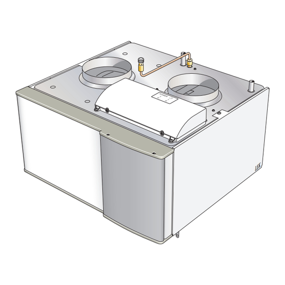
Page 8: The Design Of The Exhaust Air Module
3 The design of the exhaust air module BT21 XL32 QM21 XL31 BT20 PF 1 HQ10 AA100 AA5-S2 BT20 XL31 QM21 XL32 BT26 BT27 HQ10 AA100 BT21 EP16 XL40 BT26 BT27 Chapter 3 | The design of the exhaust air module NIBE FLM... - Page 9 Exhaust air module Electrical components Accessory card NIBE FLM AA5-S2 Dip switch AA100 Joint card Pipe connections Switch, position 0 - 1, main switch Connection, brine in, compression ring Ø 15 Switch, position 0 - 1, circulation pump Potentiometer Connection, brine out, compression ring Ø 15...
-
Page 10: Pipe And Ventilation Connections
Symbol key Symbol Meaning Venting valve Shut-off valve Control valve Trim valve Shunt / shuttle valve Safety valve Expansion vessel Pressure gauge Circulation pump Particle filter Chapter 4 | Pipe and ventilation connections NIBE FLM... - Page 11 (QM21). When venting, the switch for circulation pump (SF2) must be set to ”0”. Standard installation Standard installation, where ventilation air is led to NIBE FLM and then out of the house. NIBE FLM Chapter 4 | Pipe and ventilation connections...
-
Page 12: Dimensions And Pipe Connections
Dimensions and pipe connec- tions Chapter 4 | Pipe and ventilation connections NIBE FLM... -
Page 13: Mounting
1. Remove the front cover from the heat pump. 2. Remove the top panel from the heat pump (in- stalled with 6 x screws). 3. Install NIBE FLM from the top and slide into posi- tion. 4. Secure NIBE FLM with the 2 supplied screws. -
Page 14: Condensation Water Hose
1. Connect the condensation water hose to the drip- pan drain (XL40). 2. Shape the hose into a water seal (see image). If NIBE FLM is connected to F1245/F1255 there is space for the hose and the water seal in the heat pump's insulation. -
Page 15: Installation Alternative
Installation alternative At the same time, FLM circulates air from a substantial exhaust air valve in, for example, a hall to the other rooms where cooling is required, normally two to three Passive cooling bedrooms. Where passive cooling can be prioritised, NIBE FLM can be installed in the brine circuit after the heat pump in the direction of flow. -
Page 16: General Ventilation Connection
General ventilation connection Ventilation flow Ventilation installation must be carried out in accord- Connect NIBE FLM so that all exhaust air except exhaust ance with current norms and directives. air duct air (kitchen fan) passes the heat exchanger (EP1) in the exhaust air module. Lowest ventilation flow To prevent fan noise being transferred to the ventila- must comply with applicable standards. -
Page 17: Electrical Connections
Signal cables to external connections must not be ■ laid close to high current cables. If the supply cable is damaged, only NIBE, its service ■ representative or similar authorised person may re- place it to prevent any danger and damage. - Page 18 X5:7 Yellow/green for NIBE FLM no. 1 on the terminal block in the heat pump. If this is the case, remove the plug on the con- nection cable (W1) and then connect the cable to the...
- Page 19 (AA5-X4) in NIBE FLM no. 2. AA2-X6 F1145 NIBE FLM NIBE FLM F1145/F1155 NIBE FLM no. 4 is connected in a similar way in NIBE FLM no. 3. Use cable type LiYY, EKKX or similar. NIBE markvärmepump AA101:X10 AA2-X6...
- Page 20 The DIP switch (AA5-S2) must be set as follows. Connecting to another heat pump In cases where NIBE FLM is installed together with an- other heat pump, connect the exhaust air module to a grounded single phase wall socket or through a per- manent installation.
- Page 21 If the room sensor is used in a room with underfloor heating, it should only have an indicatory function, not control of the room temperature. AA3-X6 1 2 3 4 5 6 7 8 9 F1245 NIBE FLM RG05 External AA3-X6 BT50 Caution Changes of temperature in accommodation take time.
-
Page 22: Commissioning And Adjusting
6 Commissioning and adjusting Preparations 1. Check that the switch (SF1) for NIBE mark- värmepump is in position "O". 2. Check that the filling valves are fully closed (see QM21 image below). Filling and venting Caution Insufficient venting can damage internal components in NIBE FLM. -
Page 23: Start-Up And Inspection
The start guide can be started later in menu 5.7. The brine flow over NIBE FLM is regulated by the circu- lation pump GP2 and trim valve RN1 so that the tem- perature difference on brine in and out from NIBE FLM Start-up with NIBE markvärmepump... - Page 24 5. Start the heat pump. Starting-up with ventilation only 100% 100% In cases where NIBE FLM is to be run with ventilation only, e.g. before the brine side is ready for connection. In this mode the circulation pump must be switched off.
- Page 25 GP1-SF4 Pressure Capacity circulation pump Tryck (kPa) (kPa) Flöde Flow (l/h) 1000 1200 (l/h) Power output Output circulation pump Effekt Flow Flöde (l/h) (l/h) 1000 1200 NIBE FLM Chapter 6 | Commissioning and adjusting...
-
Page 26: Service
It is usually easier to start the circulation pump with NIBE FLM running, switch (SF1) set to " 1". If the circu- lation pump is helped to start while NIBE FLM is run- ning, be prepared for the screwdriver to jerk when the pump starts. -
Page 27: Disturbances In Comfort
8 Disturbances in comfort If NIBE FLM is not installed together with NIBE mark- NOTE värmepump, go directly to section Troubleshooting. To select aid mode an alarm action must be In most cases, the heat pump NIBE markvärmepump selected in the menu 5.1.4. - Page 28 Choked water seal. ■ Check and adjust the condensation water hose. ■ Chapter 8 | Disturbances in comfort NIBE FLM...
-
Page 29: Accessories
9 Accessories Brackets Wall mounting of NIBE FLM. Part no. 067 083 NIBE FLM Chapter 9 | Accessories... -
Page 30: Technical Data
10 Technical data Dimensions and setting-out coordinates Ø160 Chapter 10 | Technical data NIBE FLM... -
Page 31: Technical Specifications
Sound power level according to EN 12,102 Sound power level (L dB(A) 36-46 W(A) Dimensions and weight Width Depth Height Weight Part No. 067 011 The value varies with the selected fan curve. NIBE FLM Chapter 10 | Technical data... -
Page 32: Electrical Circuit Diagram
Electrical circuit diagram Chapter 10 | Technical data NIBE FLM... - Page 33 NIBE FLM Chapter 10 | Technical data...
-
Page 34: Index
Removing the covers, 5 Start-up and inspection, 21 Condensation water hose, 12 Connecting to another heat pump, 18 Safety information, 2 Connecting to NIBE markvärmepump, 16 Contact information, 4 Contact information, 4 Inspection of the installation, 3 Marking, 2 Serial number, 2... - Page 36 WS name: -Gemensamt WS version: a34 (working edition) Publish date: 2015-06-09 11:33 NIBE AB Sweden Hannabadsvägen 5 Box 14 SE-285 21 Markaryd info@nibe.se www.nibe.eu 031375...
Need help?
Do you have a question about the FLM and is the answer not in the manual?
Questions and answers