Table of Contents
Advertisement
Advertisement
Table of Contents

Related Manuals for Webasto FCF Series


Summary of Contents for Webasto FCF Series
- Page 1 FEEL COOL FAST MARINE AIR CONDITIONER Installation & Operation Manual 8/2018...
-
Page 2: Table Of Contents
Table of Contents INTRODUCTION ..............................5 PACKAGED COMPONENTS ..........................6 OVERVIEW ................................. 6 INSTALLATION ..............................7 Unpacking and Inspection ............................7 Safety Considerations ............................. 7 Placement of System ............................... 8 Blower Assembly ..............................10 Mounting Brackets ..............................10 Supply & Return Air Grilles and Transition Boxes....................10 Ducting ................................... -
Page 3: Introduction
Introduction Thank you for your purchase. No matter which of the following features was the reason for your purchase, we are sure it will meet your needs and give many years of efficient and trouble free use. These air conditioners are designed for marine applications incorporating the following features: •... -
Page 4: Packaged Components
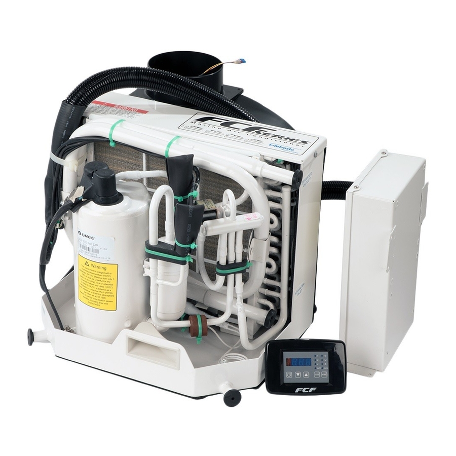
Packaged Components ITEM QUANTITY Air Conditioning unit Mounting Bracket Fuses (3.15 AL 250V) Remote controller with batteries Digital Display / Cable Duct Ring / Hardware Blower Insulation Foam Installation / Operation Manual Overview All units are manufactured without service ports HOW IT WORKS Your self-contained air conditioner consists of four main components and a refrigerant gas circulating through the system. -
Page 5: Installation
Installation Unpacking and Inspection When the equipment is received, all items should be carefully checked according to the packaged components list within this manual to ensure all components have been received. Examine components for shipping damage. If the unit is damaged, the carrier should make the proper notation on the delivery receipt acknowledging the damage. Safety Considerations VERY IMPORTANT: Never install your air conditioner in the bilge or engine room areas. -
Page 6: Placement Of System
Placement of System Selecting a good location for your air conditioner is the most important part of your preparation. Be sure to consider the size of the area you are cooling, the air distribution needs, and the size of the unit you have chosen. Keeping in mind that cool air has a tendency to fall;... - Page 7 Tools required: The unit should be installed as low as possible, BUT NEVER IN THE BILGE • OR ENGINE ROOM AREAS, ENSURE THAT THE SELECTED LOCATION Screws drivers • IS SEALED FROM DIRECT ACCESS TO BILGE AND/OR ENGINE ROOM Pliers •...
-
Page 8: Blower Assembly
Condensate Drains The condensate drain pan is 2” (50mm) deep with four drain locations. During conditions of high humidity, condensate may be produced at a rate of approximately 1/2 gallon per hour (1.9 liters per hour). It is important to route condensate drains downward to a sump pump. -
Page 9: Ducting
Ducting Good airflow is critical for the performance of the entire system. It is highly dependent on the quality of the ducting installation. The ducting should be run as straight, smooth and taut as possible minimizing the number of 90 degree bends (two tight 90°... - Page 10 Summary of the seawater system installation: 1. Install the speed scoop thru-hull inlet as close to the keel and as far below the water line as possible, facing forward. Bed the scoop with a marine sealant designed for underwater use. 2.
-
Page 11: Electrical Connections, Grounding And Bonding
Electrical Connections, Grounding and Bonding Turn off air conditioner power supply circuit breaker before opening electric box. All air conditioner units have a terminal strip mounted inside the electric box. The terminal strip is labeled for proper connections of the electrical supply, ground wires and pump circuits. A wiring diagram is provided in the electrical box and later in this manual. -
Page 12: Digital Display Installation
Digital Display Installation DO NOT turn the unit off and immediately turn it back on. Wait at least 30 seconds for refrigerant pressures to stabilize. Before mounting the digital display, consider the location. The digital display should never be mounted in direct sunlight or exposed to excessive moisture. -
Page 13: Installation Checklist (Review Prior To Installation)
Installation Checklist (Review Prior To Installation) Seawater cooling system: Speed scoop located as far below the water line and as close to the keel as possible Shut off valve (sea cock) and speed scoop properly sealed and tightened Seawater pump is at least 1’ (305mm) below water line and securely mounted Strainer mounted below pump with access to filter Double/reversed stainless steel hose clamps on all hose connections Thread sealer on all threaded connections... -
Page 14: Wiring Diagrams
Wiring Diagrams Power 115V ~ 60Hz 115V ~ 60Hz Line In 115V ~ 60Hz Neutral Cooling Pump Line In Cooling Pump Neutral Power 208V / 230V ~ 60Hz 208V / 230V ~ 60Hz Line In 208V / 230V ~ 60Hz Neutral Cooling Pump Line In Cooling Pump Neutral... - Page 15 Fuse = 3.15 AL 250V...
- Page 16 Fuse = 3.15 AL 250V...
- Page 17 Fuse = 3.15 AL 250V...
- Page 18 Fuse = 3.15 AL 250V...
-
Page 19: Operation
Operation Digital Display Operation • Don't install the digital display in a location where it can get wet. • Don’t knock, throw or open the digital display. 1. Remote receiver 6. Fan control button 2. Display 7. Temp. Setting button (Increasing) 3. -
Page 20: Power On/Off
Power ON/OFF • Press ON/OFF button to turn the unit display on. Press the ON/OFF button a second time to select mode and start operation. • While the display is active press the ON/OFF button once to turn the unit OFF. Press the ON/OFF button a second time if the display has already entered sleep mode to turn the unit OFF. - Page 21 DEHUMIDIFY Mode Operation • In “DEHUMIDIFY” mode, the LED next to the icon will illuminate when mode is selected on the digital display. • In DEHUMIDIFY mode, if the indoor temperature is higher than temperature setting, the unit will run in cooling mode and the fan will run on low speed.
-
Page 22: Remote Control Operation - V1
Remote Control Operation – V1 Wakes up Digital Display... -
Page 23: Remote Control Operation - V1 (Continued)
Remote Control Operation – V1 (continued) Liquid Crystal Display. Opening cover while unit is on will not affect unit operation. NOTE: This is a universal remote; the sleep and timer ON/OFF buttons are not used with this application. - Page 24 Battery Replacement - Remote Control – V1 Remote controller battery requirements: Two AAA alkaline cells. 1. Slide the cell cover downward to take out the worn cells. Replace the worn cells. (Note to the correct polarity). 2. Close the cell cover. 3.
-
Page 25: Remote Control Operation - V2
Remote Control Operation – V2 Version 2 (V2) remote controls are used on FCF models equipped with digital displays from version 30 and newer. If replacing a lost remote control, look on the data tag on the rear of the control panel. For version 29 and older, order version 1 (FCF Classic), for version 30 and newer, order version 2 (FCF Platinum). -
Page 26: Error Codes
Error Codes When there are faults within the system, an error code will be displayed on the display controller: Power off the unit and contact professional service. Error code Description Compressor high pressure protection – check sea water flow Evaporator freezing protection – check air flow and outlets Compressor low pressure protection Communication error Ambient temperature sensor error... - Page 27 No cooling or Seawater temperature too high for cooling or too Seawater temperature will directly affect the air heating low for heating. conditioning unit’s efficiency. This air conditioning unit (continued) can effectively cool your boat in water temperature up to F and heat (if reverse cycle option is installed) in water as low as 40 Coil is iced (in cooling)
-
Page 28: Maintenance
water as low as 40 Improper air sensor location. Check your specific control troubleshooting section, Digital display is 4-pin display cable plugs are not making contact With POWER OFF at the circuit breaker, remove not lit. (unplugged, dirty, bent, or broken pins). connector and inspect. -
Page 29: Return Air Filters
Return Air Filters Check the return air filter about once a month and clean as necessary. To clean the filter, remove it from the unit, rinse with water, air dry and reinstall. (Do not used compressed air) Winterization There are several methods of winterization, some of which work better than others. There are various methods employed using a 50/50 non-polluting biodegradable anti-freeze/water solution. - Page 30 ** Slow Delay Unit Dimensions & Technical Specifications BTU Capacity 5000 9000 12000 16000 24000 Capacity in kW Voltage (V) 115 Soft Frequency (Hz) Running Current (A) 12.4 20.4 12.5 Starting surge (A) 23.5 15.5 13.5 36.5 16.5 54.5 25.5 26.5 Starting Time (ms) 150 160...
-
Page 31: Limited Warranty
This product comes with a 24 month limited warranty from the date of purchase. For warranty policy details, visit http://www.techwebasto.com. To obtain warranty service, contact a customer service representative at: (800) 860-7866 or e-mail at: info-us@webasto.com. Technical Assistance If you require help, check our technical assistance website at http://www.techwebasto.com... - Page 32 Webasto Thermo & Comfort N.A., Inc. Technical Assistance Hotline Phone: (800) 860-7866 Outside U.S. (810) 593-6000 www.webasto.us www.techwebasto.com Original 7/2006 | Rev. L | Date: 8/2018...
Need help?
Do you have a question about the FCF Series and is the answer not in the manual?
Questions and answers