Advertisement
Quick Links
Webasto
F
U
ELETRICAL
CONTROL
N
BOX
C
T
POWER CABLE
I
O
FLEXIBLE AIR DUCT
SELF-CONTAINED CPAC
N
UNIT - 7000 TO 32000 BTU
- BLOWER EXIT TURNED
UPWARDS
I
N
G
P
R
SEA-WATER PUMP
I
N N E E W W E E L L E E C C T T R R O O N N I I C C S S - - 2 2 0 0 0 0 0 0 S S E E R R I I E E S S
N
C
I
P
COOL CYCLE LED
BLOWER LED
L
HEAT CYCLE LED
E
ON/OFF KEY
S
Edition dated 1st January 2004
- AIR CONDITIONING
SELF-CONTAINED UNITS - WBCC SERIES
OPERATION AND INSTALLATION MANUAL
DISPLAY CABLE
TRANSITION BOX + SUPPLY
AIR-GRILLE
STRAINER
SELF CONTAINED UNITS
Operation/Installation Manual - WBCC Series - Page : 1
RETURN AIR-GRILLE
OVER-BOARD DISCHARGE
19.4
Operation/Installation Manual - WBCC Series - Page : 1
DIGITAL CONTROL
PANEL
ROOM TEMPERATURE OR
SET-POINT TEMPERATURE
OR SECONDARY FUNCTION
READ-OUT
F/BLOWER KEY - GIVES
ACCESS TO BLOWER SPEED
CONTROL AND SECONDARY
FUNCTIONS
SET-POINT MODIFICATION
KEYS
Advertisement

Related Manuals for Webasto WBCC Series


Summary of Contents for Webasto WBCC Series
-
Page 1: Air Conditioning
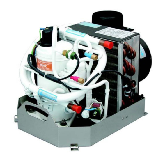
Operation/Installation Manual - WBCC Series - Page : 1 Webasto - AIR CONDITIONING SELF-CONTAINED UNITS - WBCC SERIES OPERATION AND INSTALLATION MANUAL ELETRICAL CONTROL DISPLAY CABLE POWER CABLE TRANSITION BOX + SUPPLY DIGITAL CONTROL AIR-GRILLE PANEL FLEXIBLE AIR DUCT SELF-CONTAINED CPAC... -
Page 2: Table Of Contents
Operation/Installation Manual - WBCC Series - Page : 2 SELF-CONTAINED AIR-CONDITIONING UNITS - WBCC SERIES OPERATION AND INSTALLATION MANUAL C O N T E N T S Page 1) General Information ....................2) Digital Control - Operation Guidelines ..............2.1 - Digital Display <AIR CONTROL> - Basic Commands ........ -
Page 3: General Information
Operation/Installation Manual - WBCC Series - Page : 3 HOW DOES IT WORK ? All air-conditioning units based on her- refrigerant is injected through a small orator coil. metic compressors function on the same nozzle and evaporates. This evaporation While passing through the evaporator the principle : a compressor compresses the process produces the refrigeration effect. - Page 4 Operation/Installation Manual - WBCC Series - Page : 4 2 - DIGITAL WBCC/BLOWER CONTROL - GENERAL PRINCIPLES BASIC COMMANDS : 1 - Press to turn on - press again to turn off. 2 - Press to read set-point temperature - hold to raise set-point temperature.
-
Page 5: Visual Error Codes - Digital Display
Operation/Installation Manual - WBCC Series - Page : 5 B) Calibrate all blower speed settings D) Infra-Red Remote Control : automatically when the display in real time mode. goes back to room temperature Infra-red remote control can be obtained as... -
Page 6: Central Blower Control
Operation/Installation Manual - WBCC Series - Page : 6 code and will be followed by a system halt. water cooling - check sea-water Whenever any of these codes appear the sys- pump. The digital control is initially programmed tem is stopped for approx. 60 seconds and - too much refrigerant in system - by the manufacturer in second - i.e. -
Page 7: Digital Display
Operation/Installation Manual - WBCC Series - Page : 7 6 - DIGITAL DISPLAY <AIR CONTROL> - PROGRAMMING ACCESS PROGRAMMING MODE : To enter programming mode : raise or lower set-point to 29 or 15° C. Turn off system by pressing <Power> key - 14.- Programming Access - Page 8 Operation/Installation Manual - WBCC Series - Page : 8 During low-voltage cut-out the display panel Code <8> : idem speed N° 3 according to the number of compressors will show the 3 letters <AAA>. Code <9> : idem speed N° 2 effectively on line, the TCC controller card Code <A>...
-
Page 9: Routine Checks
Operation/Installation Manual - WBCC Series - Page : 9 Introduce shut-off valves for each unit if 1 2) The digital display shows 3 lettres pump provides cooling for more than 1 <AAA>. This means a persistent state of air-conditioning unit. -
Page 10: Air-Ducting And Ventilation
Operation/Installation Manual - WBCC Series - Page : 10 9 - AIR DUCTING - VENTILA- Also the size of the transition boxe behind maximum possible length to obtain max. the supply air-grille is important. interior smoothness. TION See table here-under to choose correct grille For very long duct sections preference should sections according to BTU rating. - Page 11 Operation/Installation Manual - WBCC Series - Page : 11 10 - W I R I N G D I A G R A M S 10.1 - Wiring diagram WBCC 5000 TO 16000 BTU (Rotary Comp.) - single phase ATT. DIPSWITCH SETTINGS...
- Page 12 Operation/Installation Manual - WBCC Series - Page : 12 10.2 - ELECTRICAL WIRING - WBCC 24 TO 30 - SINGLE-PHASE ATT. DIPSWITCH SETTINGS BLACK = PUSHED DOWN OPEN Operation/Installation Manual - WBCC Series - Page : 12 Edition dated 1st January 2004...
- Page 13 Operation/Installation Manual - WBCC Series - Page : 13 10.3 - ELECTRICAL WIRING - WBCC 7 TO 16 - 1 PHASE - PISTON COMPR. DIPSWITCH SELECTOR ATT. DIPSWITCH SETTINGS BLACK = PUSHED DOWN DISPLAY CABLE CONNECTOR EXTERNAL AIR TEMP. SENSOR EVAPORATOR COIL TEMP.
Need help?
Do you have a question about the WBCC Series and is the answer not in the manual?
Questions and answers