Table of Contents
Advertisement
Advertisement
Table of Contents

Related Manuals for Webasto FCF 5,000


Summary of Contents for Webasto FCF 5,000
- Page 1 MARINE AIR CONDITIONER Installation & Operation Manual...
-
Page 3: Table Of Contents
Table of Contents INTRODUCTION ................................4 OVERVIEW ................................5 INSTALLATION ................................6 UNPACKING AND INSPECTION ..........................6 SAFETY CONSIDERATIONS ..........................6 PLACEMENT OF SYSTEM.............................7 CONDENSATE DRAINS ............................8 BLOWER ASSEMBLY.............................8 MOUNTING BRACKETS ............................8 SUPPLY & RETURN AIR GRILLES AND TRANSITION BOXES ................8 DUCTING ................................9 SEAWATER PUMP AND PLUMBING ........................9 ELECTRICAL CONNECTIONS, GROUNDING AND BONDING ................ -
Page 4: Introduction
Operation / Installation Manual – FCF 5,000, 9,000, 12,000, 16,000 INTRODUCTION Thank you for your purchase. No matter which of the following features was the reason for your purchase, we are sure it will meet your needs and provide many years of efficient and trouble free use. The FCF Series air... -
Page 5: Overview
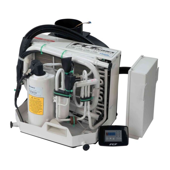
Operation / Installation Manual – FCF 5,000, 9,000, 12,000, 16,000 OVERVIEW HOW IT WORKS Your self-contained air conditioner consists of four main components and a refrigerant gas circulating through the system. The BLOWER draws warm cabin air across the fins on the EVAPORATOR where the heat from the air is transferred to the refrigerant in the evaporator coil. -
Page 6: Installation
Operation / Installation Manual – FCF 5,000, 9,000, 12,000, 16,000 INSTALLATION UNPACKING AND INSPECTION When the equipment is received, all items should be carefully checked against the packing list to ensure all cartons have been received. Move units in the normal "up" orientation as indicated by the arrows on each carton. Examine cartons for shipping damage, removing the units from the cartons if necessary. -
Page 7: Placement Of System
Operation / Installation Manual – FCF 5,000, 9,000, 12,000, 16,000 PLACEMENT OF SYSTEM Selecting a good location for your air conditioner is the most important part of your preparation. Be sure to consider the size of the area you are cooling, the air distribution needs, and the size of the unit you have chosen. Keeping in mind that cool air has a tendency to fall;... -
Page 8: Condensate Drains
Operation / Installation Manual – FCF 5,000, 9,000, 12,000, 16,000 CONDENSATE DRAINS The condensate drain pan is 2” (50mm) high with two drain locations. During conditions of high humidity, condensate may be produced at a rate of approximately a 1/2 gallon per hour (1.9 liters per hour). With this in mind, it is important to route condensate drains downward to a sump pump. -
Page 9: Ducting
Operation / Installation Manual – FCF 5,000, 9,000, 12,000, 16,000 DUCTING Good airflow is critical for the performance of the entire system. It is highly dependent on the quality of the ducting installation. The ducting should be run as straight, smooth and taut as possible minimizing the number of 90°... - Page 10 Operation / Installation Manual – FCF 5,000, 9,000, 12,000, 16,000 tape on all threaded connections. Summary of the seawater system installation: 1. Install the speed scoop thru-hull inlet as close to the keel and as far below the water line as possible, facing forward.
-
Page 11: Electrical Connections, Grounding And Bonding
Operation / Installation Manual – FCF 5,000, 9,000, 12,000, 16,000 ELECTRICAL CONNECTIONS, GROUNDING AND BONDING All a/c units have a terminal strip mounted inside the electric box. The terminal strip is labeled for proper connections of the electrical supply, ground wires and pump circuits. A wiring diagram is provided in the electrical box and later in this manual. -
Page 12: Wired Remote Controller Installation
Operation / Installation Manual – FCF 5,000, 9,000, 12,000, 16,000 WIRED REMOTE CONTROLLER INSTALLATION DO NOT turn the unit off and immediately turn it back on. Wait at least 30 seconds for refrigerant pressures to stabilize. Before mounting the wired display, consider the location. The display panel should be mounted on an inside wall, slightly higher than mid-height of the cabin. -
Page 13: Installation Checklist (Review Prior To Installation)
Operation / Installation Manual – FCF 5,000, 9,000, 12,000, 16,000 INSTALLATION CHECKLIST (Review Prior To Installation) Seawater cooling system: Speed scoop located as far below the water line and as close to the keel as possible Shut off valve (sea cock) and speed scoop properly sealed and tightened Seawater pump is at least 1’... -
Page 14: Wiring Diagrams
Operation / Installation Manual – FCF 5,000, 9,000, 12,000, 16,000 WIRING DIAGRAMS Power 115V ~ 60Hz 115V ~ 60Hz Line In 115V ~ 60Hz Neutral Cooling Pump Line In Cooling Pump Neutral Power 208V / 230V ~ 60Hz 208V / 230V ~ 60Hz Line In... - Page 15 Operation / Installation Manual – FCF 5,000, 9,000, 12,000, 16,000 Wiring Diagram FCF 5,000 (115v/230v) – FCF 9,000 (115v/230v) (FCF 9,000 230v comes with a Panasonic Compressor; all other model are equip with Samsung Compressors) Wiring Diagram FCF 12,000 (115v/230v) – FCF 16,000 (115v/230v)
-
Page 16: Operation
Operation / Installation Manual – FCF 5,000, 9,000, 12,000, 16,000 OPERATION WIRED DISPLAY CONTROL OPERATION Don't install the wired display in a location where it can get wet. 1. Display Receiver 6. Fan Speed Button 2. Digital Display 7. Temp. Setting Button / Increasing 3. -
Page 17: Power On/Off
Operation / Installation Manual – FCF 5,000, 9,000, 12,000, 16,000 Power ON/OFF Press ON/OFF button to turn the unit on Pressing the ON/OFF button a second time will turn the unit off FAN Control Press the FAN button, the fan speed will change in the following order: →... -
Page 18: Display Fahrenheit Or Centigrade
Operation / Installation Manual – FCF 5,000, 9,000, 12,000, 16,000 Display Fahrenheit or Centigrade Pressing the ▲ and ▼ key simultaneously, will switch between Fahrenheit Centigrade modes. Error Codes When there are faults within the system, an error code will be displayed on the display controller: Power off the unit and contact professional service. -
Page 19: Auto -Off Function Of The Manual Controller
Operation / Installation Manual – FCF 5,000, 9,000, 12,000, 16,000 When performing this setup or value change, ensure the wireless remote is not in site of any display as this could potentially change values prior to confirming set value. (Make sure to confirm new values by simultaneously holding the ▲... -
Page 20: Remote Control Operation
Operation / Installation Manual – FCF 5,000, 9,000, 12,000, 16,000 REMOTE CONTROL OPERATION Be sure that there are no obstructions between the remote and controller. ● The remote control signal can be received up to a distance of 33’ (10m). -
Page 21: Button / Function And Description (Cover Open)
Operation / Installation Manual – FCF 5,000, 9,000, 12,000, 16,000 Button / Function and Description (Cover Open) Mode Operations COOL Mode Operation ● According to the difference between room temperature and set temperature, the microcomputer will decide if cooling mode is on or off. -
Page 22: Battery Replacement In Wireless Remote Control
Operation / Installation Manual – FCF 5,000, 9,000, 12,000, 16,000 DEHUMIDIFY mode operation ● In DEHUMIDIFY mode, if the indoor temperature is higher than temperature setting, the unit will operate in cooling mode and the fan will run on low speed ●... -
Page 23: Troubleshooting
Operation / Installation Manual – FCF 5,000, 9,000, 12,000, 16,000 TROUBLESHOOTING FAULT POSSIBLE REASON CORRECTION Will not start A/C circuit breaker is off Turn circuit breaker on at ship's panel, See control operation section in this manual. Display control is not turned on. - Page 24 Operation / Installation Manual – FCF 5,000, 9,000, 12,000, 16,000 Continued: FAULT POSSIBLE REASON CORRECTION Low air flow Air flow is blocked Remove any obstructions in return air stream, Clean return air filter and grille. Check for crushed or restricted ducting, ducting must be as straight, smooth and taut as possible.
-
Page 25: Maintenance
Operation / Installation Manual – FCF 5,000, 9,000, 12,000, 16,000 MAINTENANCE REVERSING VALVES Reverse cycle units have a reversing valve; the valve must be energized periodically to keep the internal parts moving freely. To do this, switch the a/c unit into heat for a few seconds once a month. -
Page 26: Winterization
Operation / Installation Manual – FCF 5,000, 9,000, 12,000, 16,000 WINTERIZATION There are several methods of winterization, some of which work better than others. There are various methods employed using a 50/50 non-polluting biodegradable anti-freeze/water solution. Any method that causes the anti-freeze solution to flow downward is the method of choice. -
Page 27: Unit Dimensions & Technical Specifications
Operation / Installation Manual – FCF 5,000, 9,000, 12,000, 16,000 Unit Dimensions & Technical Specifications Unit Dimensions & Technical Specifications BTU Capacity 5000 9000 12000 16000 Capacity in kW Voltage 115V/230V 115V/230V 115V/230V 115V/230V Frequency 60Hz 60Hz 60Hz 60Hz Aver. Load Amps 4.8A/2.2A... -
Page 28: Limited Warranty
Operation / Installation Manual – FCF 5,000, 9,000, 12,000, 16,000 LIMITED WARRANTY This product comes with a 24 month limited warranty from the date of purchase. To obtain warranty service, contact a customer service representative at: (800) 860-7866 or e-mail at:... - Page 29 Operation / Installation Manual – FCF 5,000, 9,000, 12,000, 16,000 Notes: Page 29...
- Page 30 Webasto Product N.A., Inc. Technical Assistance Hotline Phone: (800) 860-7866 Outside U.S. (810) 593-6000 Rev. B - Date: May 7, 2009...
Need help?
Do you have a question about the FCF 5,000 and is the answer not in the manual?
Questions and answers