
Summary of Contents for Unipulse F159
- Page 1 F159 PLUG-IN WEIGHT MODULE for the OMRON SYSMAC CJ1 SERIES PLC OPERATION MANUAL 07 Nov. 2008 Rev. 1.02...
- Page 2 The applications for the F159 weigh module includes: Hopper scales, Packing scales, Bag filling systems, Rotary filling systems and many other weight based control systems. The F159 can excite up to four (4) 350 ohm load cells while still providing up to 1/40,000 division resolution.
- Page 3 Safety Precautions Safety Precautions Be sure to read for safety. In order to have an F159 Weight Module used safely, notes I would like you to surely follow divide into , and are indicated by the following documents. WARNING CAUTION Notes indicated here are the serious contents related to safety.
- Page 4 Safety Precautions WARNING ● Use F159 with correct supply voltage. ● Do not carry out the direct file of the commercial power supply to a signal input terminal. ● Carefully check wiring, etc. before applying power. ● Do not disassemble the main body for modifications or repair.
- Page 5 Safety Precautions CAUTION ● Be sure to disconnect the power cable when performing the following. - Wiring/connection of cables to terminal blocks. ● Take an interval of more than 5 seconds when repeating ON/OFF. ● Use shielded cables for the connection of strain gauge type sensor or External output. ●...
-
Page 6: Table Of Contents
3-1.High Performance I/O Unit Restart Flag ........... 15 3-2.Relay Area ................... 16 3-2-1 Allocation of Weight and Status Data ..........16 3-2-2 OUT (CPU unit → F159) ..............16 3-2-3 IN (F159 → CPU unit) ............... 19 3-2-4 Register Allocations for Weighing Control ........28... - Page 7 CONTENTS 4.CALIBRATION ..............37 4-1.What is Calibration? ................37 4-2.Actual Load Calibration Procedure ........... 38 4-3.Preparation for Calibration ..............39 4-3-1 LOCK Release .................. 39 4-3-2 Setting Initial Data ................40 4-4.Zero Calibration .................. 44 4-5.Span Calibration ................. 47 5.DISPLAY SETTINGS ............50 5-1.Digital Filter ..................
- Page 8 CONTENTS 6.WEIGHING MODE SETTING AND OPERATION ....59 6-1.Feed Weighing and Discharge Weighing ......... 60 6-1-1 Feed Weighing ................. 60 6-1-2 Discharge Weighing ................ 63 6-1-3 Weighing Mode ................66 6-2.Simple Comparison Control and Sequence Control ....... 67 6-2-1 Simple Comparison Control ............67 6-2-2 Sequence Control ................
- Page 9 CONTENTS 11.DIMENSIONS ..............107 12.INSTALLATION ..............108 12-1.Connection with CJ1 Unit .............. 108 12-2.DIN Rail Installation ................ 110 13.SPECIFICATIONS ............112 13-1.Analog Section ................112 13-2.Display ..................... 113 13-3.Setting ....................113 13-4.General Specifications ..............114 14.STATEMENT OF CONFORMATION TO EC DIRECTIVES 115...
-
Page 10: 1. Appearance Description
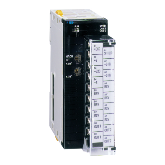
1.APPEARANCE DESCRIPTION 1. APPEARANCE DESCRIPTION 1-1. Front Panel Status LED +EXC SHILD Terminal block Unit number select switch +SIG -EXC -SIG OUT1 OUT2 DIP switch. OUT1 The switch is located OUT2 beneath the terminal block. CAUTION Terminal block can be detached by pulling down the lever. -
Page 11: Status Led
Name State Description Normal operation Operation status (Green) Data exchange with CPU has been aborted Error occurred in F159 Error detected by the unit (Red) Normal operation Error occurred during data exchange with CPU CPU error (Red)... -
Page 12: Unit Number Select Switch
MAC CJ1 series PLC. The data exchange between CPU unit and F159 are carried out by the high performance relay area of I/O and DM area. Relay and DM number used by F159 can be selected by the unit number selection switch located on the front panel. -
Page 13: Dip Switch
Undefined Undefined Undefined When switch 2 is set to ON position, F159 initializes set value whenever F159 is powered on. Switch 3 and 4 are undefined: they should always be set to OFF position. When they are set to ON position, F159 can’t operate normally. -
Page 14: 2.Connection
2-1. F159 Block Terminal +EXC SHIELD +SIG -EXC -SIG OUT1 OUT2 OUT1 OUT2 2-2. Load Cell Connection Connect leads from the load cell to F159 terminal block. Load cell signal F159 6-wire connection 4-wire connection +EXC +EXC +EXC connected to +EXC -EXC -EXC... -
Page 15: 6-Wire Connection
2.CONNECTION 2-2-1. 6-wire Connection F159 input uses an accurate 6-wire load cell connection (remote sense method). Use shielded 6-core cable for this connection and route it apart from noisy lines (power and digital devices) and AC power lines. Load cell +... - Page 16 2.CONNECTION CAUTION ・ F159 supplies 10V excitation voltage. Use a load cell with rated excitation voltage of 10V or higher, otherwise abnormal heating and damage to the cell may result. ・If you use F159 using 4-wire connection configuration, never fail to connect between +EXC and +S, and –EXC and –S.
-
Page 17: Connecting Load Cells In Parallel
Some industrial applications require multiple of load cells connected in parallel to configure, for example, a hopper scales or track scale. A typical parallel connection is shown below. Parallel connection can easily realized using the 4-point multi load cell summing box (e.g. B41X series provided by UNIPULSE). +EXC CAUTION -SIG... - Page 18 2.CONNECTION 2-2-3-1. Power consumption evaluations for parallel connection Power consumed by a F159 can vary depending on the number of load cells connected in parallel. For an each additional 350Ω load cell, power requirement will increase by approx.0.13 A. Power Number of 350Ω...
- Page 19 2.CONNECTION <Connection of single 350Ω load cell> Power unit PA202 Source capacity CPU unit Input unit Output unit F159 F159 F159 End cover 5[V] 2.8[A] CJ1M-CPU11 CJ1W-ID211 CJ1W-OD211 Power consumption → 0.58[A] 0.08[A] 0.10[A] 0.30[A] 0.30[A] 0.30[A] Single load cell connection...
- Page 20 2.CONNECTION <Connection of three 350Ω load cells in parallel> Power unit PA205R Source capacity CPU unit Input unit Output unit F159 F159 F159 End cover 5[V] 5[A] CJ1M-CPU11 CJ1W-ID211 CJ1W-OD211 Power consumption → 0.58[A] 0.08[A] 0.10[A] 0.56[A] 0.56[A] 0.56[A] Three load cells are connected in parallel...
-
Page 21: Output Connection
2.CONNECTION 2-3. Output Connection 2-3-1. Equivalent Circuit F159 uses non-polar MOS FET relays for signal output. Vext Spark arrester F159 Inside DC source Load Relay Varistor Spark arrester Vceo=30V (max) AC source Ic =120mA (max) Load Output data MOS FET relay User must provide an external power unit (Vext <= 30... -
Page 22: Connections To Terminal Block
・ A4 to A7 and B5 to B7 are unnecessary in this specification, please do not connect input and output signal lines to them. Do not apply the voltage from the outside, or do not short-circuit with parts. It may cause malfunction of F159 and external equipment. -
Page 23: 3.Data Exchange With Cpu
Weighing setting data Settings for performing Weight measurement. One F159 is allocated, based on its unit number, to a selected DM area for high performance I/O unit (inside CPU unit). Data is written to the DM area in synchronization with: power-on, refresh start, and request bit (On-edge). Data is also read out using the request bit’s On-edge: the bit can be used both for reading... -
Page 24: High Performance I/O Unit Restart Flag
3.DATA EXCHANGE WITH CPU CJ series CPU unit F159 【High performance I/O unit relay area】 【Weight data, status data】 2000 + n × 10 Weight data Weight value, 10CH status info,… I/O refresh Status data 2000 + n × 10 + 9 【Data memory (DM) area】... -
Page 25: Relay Area
3.DATA EXCHANGE WITH CPU 3-2. Relay Area 3-2-1. Allocation of Weight and Status Data OUT (CPU unit → F159) Digital Soft TARE TARE Feed/ n CH Judge HOLD tare LOCK STOP CPS. Discharge START subtraction n+1 CH Span Zero... - Page 26 3.DATA EXCHANGE WITH CPU TARE OFF ON edge (0 → 1) disables tare subtraction function. Set value for tare subtraction remains intact. DZ ON ON edge (0 → 1) triggers Digital Zeroing (Gross weight is zero cleared). Allowable range of digital zeroing is within the range set by DZ regulation value.
- Page 27 3.DATA EXCHANGE WITH CPU Judge This bit is used for two purposes: If Over/Under decision is to be triggered by Judge input, this signal triggers Over/ Under judgment. If Upper/Lower limit decision is to be triggered by Judge input, this signal triggers Upper/Lower limit judgment.
-
Page 28: In (F159 → Cpu Unit)
ON, or a preceding calibration process is still underway. Request ON edge (0 → 1) in this signal triggers F159 to exchange the set of weighing settings (m – m+19 CH in DM area) with CPU unit. Direction of data transfer (CPU →... - Page 29 3.DATA EXCHANGE WITH CPU Near zero “1” when Weight <= Near zero setting. Weight : Weight value Near zero SP1, SP2, SP3 Simple comparison mode SP1: “1” if Weight >= Final setting – Set point 1 setting SP2: “1” if Weight >= Final setting – Set point 2 setting SP3: “1”...
- Page 30 ・ I f t h e v a l u e f o r F i n a l i s s e t t o “ 0 ” , C o m p l e t e m a y spontaneously change to “1” when the F159 is powered.
- Page 31 3.DATA EXCHANGE WITH CPU Under, Go, Over Simple comparison mode Judgment criteria is selected in Over/Under comparison mode (Weighing function 2) Under: “1” if Weight < Final setting – Under setting Over: “1” if Weight > Final setting + Over setting “1”...
- Page 32 3.DATA EXCHANGE WITH CPU CZ (Center Zero) bit helps the user find out the center of scale interval. The Minimum scale division is divided into four sub-divisions, and CZ bit becomes “1” if reading falls within the central two sub-divisions. 1/4 of Minimum scale division Minimum scale division CZ bit “1”...
- Page 33 This bit becomes “1” while Span calibration is in progress. NOV RAM This bit becomes “1” when NOV RAM is being accessed. Do not remove power from F159 while this bit is “1”. Cyclic bit This bit toggles between “1” and “0” in approx. one second interval.
- Page 34 3.DATA EXCHANGE WITH CPU Error assistance code Combination of this bit and Error Code bit identify the nature of the error. Error Assistance Code “0” indicates that the system is currently error free. For detailed information about Error Code and Error Assistance Code, see Section 9-1.
- Page 35 3.DATA EXCHANGE WITH CPU EXC ALM This bit changes to “1” when the load cell excitation voltage falls below the scecified level. Calibration error This bit turns on “1” when one or more irregularities were found during zero/ Span calibration and the process did not complete normally. TARE ON response Returns the state of TARE ON bit.
- Page 36 3.DATA EXCHANGE WITH CPU Judge response Returns the state of Judge bit. SEQ START response Returns the state of SEQ START bit. SEQ STOP response Returns the state of SEQ STOP bit. Soft LOCK response Return the state of Soft LOCK bit. Zero calibration response Returns the state of Zero Calibration bit.
-
Page 37: Register Allocations For Weighing Control
3.DATA EXCHANGE WITH CPU 3-2-4. Register Allocations for Weighing Control Upper limit 00000 - 99999 Lower limit 00000 - 99999 Near zero 00000 - 99999 Set point 1 00000 - 99999 Set point 2 00000 - 99999 Free fall m+10 0000 - 9999 compensation Over... -
Page 38: Register Allocations For Initial Settings
3.DATA EXCHANGE WITH CPU 3-2-5. Register Allocations for Initial Settings m+20 Comparison inhibit time 0.00 - 9.99 m+21 Compare time 0.00 - 9.99 m+22 Complete output time 0.00 - 9.99 m+23 Auto jog timer 0.00 - 9.99 Auto zero times/ m+24 Judging times m+25... - Page 39 Undefined Undefined CAUTION F159 and CPU unit exchange data in BCD format. Violation of this rule will cause an unexpected operational failure. Data in “undefined” area is ignored: it is strongly recommended that these areas are filled up with “0”s.
- Page 40 3.DATA EXCHANGE WITH CPU Auto zero times /Judging times Judging times 00 - 99 AZ times 00 - 99 Weighing function 1 Near zero comparison 4:ON when |Net weight| <= Near zero set value 3:ON when |Gross weight| <= Near zero set value 2:Comparison OFF 1:ON when Net weight <= Near zero set value 0:ON when Gross weight <= Near zero set value...
- Page 41 3.DATA EXCHANGE WITH CPU Weighing function 2 Sign convention for discharge control 1:Sign of Net weight not reversed 0:Sign of Net weight reversed Completion signal output mode 2:Complete signal turns on when SP3 turns on, and remains on until Compare time expires, or, Complete signal turns on when reading becomes “stable”...
- Page 42 3.DATA EXCHANGE WITH CPU Weighing function 3 Digital tare subtraction 2:Relay selection 1:Digital tare subtraction ON 0:Digital tare subtraction OFF Avg. count of free fall compensation Number of averaging: 1-9 Free fall compensation 2:Relay selection 1:Free fall compensation enabled 0:Free fall compensation disabled Free fall compensation coefficient 3:1/4 2:2/4...
- Page 43 3.DATA EXCHANGE WITH CPU Output selection OUT1 selection OUT2 selection 8:Near zero 7:Lower limit 6:Upper limit 5:Under 4:Go 3:Over 2:SP3 1:SP2 0:SP1 Undefined Undefined Restriction on the tare subtraction Undefined Digital tare subtraction (expansion) 1:inhibit 0:don’t care Range of tare subtraction 1:0 <...
- Page 44 3.DATA EXCHANGE WITH CPU Sequence mode At start weight value confirmation 1:ON 0:OFF At start near zero confirmation 1:ON 0:OFF Auto jog 1:Enabled 0:Disabled Mode selection 1:Sequence control mode 0:Simple comparison mode Motion detection Range : 00-99 count Period : 0.0-9.9 sec Filer Digital filter :...
- Page 45 3.DATA EXCHANGE WITH CPU Stable mode Motion detection mode 1:Checker mode 0:Stable mode Digital filter 2 1:Not used (bypass) 0:Use (128 samplings) Undefined Undefined Function selection 1/4 scale division 1:ON 0:OFF Decimal place 3:0.000 2:0.00 1:0.0 0:0 Undefined Undefined...
-
Page 46: 4.Calibration
Calibration designates a procedure to adjust F159 so that it indicates correct reading corresponding to the actual weight placed on the load cell. That is, F159 must be properly adjusted to indicate 100 kg when an actual load (Weight) of 100 kg is placed on the load cell (sensing device). -
Page 47: Actual Load Calibration Procedure
MACH No. Register initial setting data to F159. To do this, either F159 Power on, power on the F159, or restart it by toggling restart flag in or restart the following sequence: OFF → ON → OFF. Set Soft LOCK bit (13th bit of n CH) to “0”. -
Page 48: Preparation For Calibration
M A C N o . Pulling down the lever releases the terminal block 2.Set DIP switch 1 to OFF position Set DIP SW-1 to OFF position 3.Turn on F159 and set Soft LOCK bit (13th bit of n CH) to “0”. -
Page 49: Setting Initial Data
Minimum data items required for performing proper calibration are: Decimal place, Balance weight value, Capacity, and Minimum scale division. Initial setting data are registered when F159 is powered on or it restarts. Decimal place Decimal place specifies numerical format used for reading display and setting parameters. - Page 50 4.CALIBRATION Minimum scale division Defines the Minimum scale division or scale interval (Input range: 1 – 100) Minimum scale division m+43 Gravitational acceleration This factor compensates regional difference in Gravitational acceleration. This factor needs not be specified if the system is used in the same area where actual load calibration took place.
- Page 51 4.CALIBRATION Amsterdam 9.813m/s Ottawa 9.806m/s Athens 9.800m/s Paris 9.809m/s Auckland NZ 9.799m/s Rio de janeiro 9.788m/s Bangkok 9.783m/s Rome 9.803m/s Birmingham 9.813m/s San Francisco 9.800m/s Brusseles 9.811m/s Singapore 9.781m/s Buenos Aires 9.797m/s Stockholm 9.818m/s Calcutta 9.788m/s Sydney 9.797m/s Capetown 9.796m/s Taichung 9.789m/s Chicago...
- Page 52 4.CALIBRATION 1/4 Scale Division This function facilitates finding the central portion within the Minimum scale division. If this function is enabled, the width of Minimum scale division is further divided into four equal width portions. If reading falls within the central two portions, CZ bit (11th bit of n+5 CH) will be set to “1”.
-
Page 53: Zero Calibration
(Calibration procedures must be performed while reading is stable) 3. Toggle the Zero calibration bit (0th bit of n+1 CH) from “0” to “1”. 4. F159 starts Zero calibration procedures when it acknowledges an ON edge (0 → 1) of the Zero calibration bit. - Page 54 4.CALIBRATION Calibration Error 2 Initial dead load exceeds the zero adjustable range of the F159. Check if the cell is loaded with any extra object. If the Calibration Error 2 persists while the system is loaded correctly, Zero calibration must be performed again after inserting a resistor between +EXC and –SIG terminals of the load cell for shifting zero point.
- Page 55 4.CALIBRATION Calibration Error 3 Initial dead load overshoots to negative range. Check if the cell is loaded in opposite direction, or +SIG and –SIG of the load cell are connected in reverse order. If Calibration Error 3 persists while load direction and cable connections are correct, Zero calibration must be performed again after inserting a resistor between +EXC and –SIG terminals of the load cell for shifting zero point.
-
Page 56: Span Calibration
(Calibration procedures must be performed while reading is stable) 4. Toggle the Span calibration bit (1st bit of n+1 CH) from “0” to “1”. 5. F159 starts Zero calibration procedures when it acknowledges an ON edge (0 → 1) of the Span calibration bit. - Page 57 Balance weight value is preset to “00000”. Select a proper non-zero value. Calibration Error 6 The load cell output falls short of the F159’s allowable span adjustment range. Check if the load cell is loaded properly, and if its output specification meets...
- Page 58 Calibration Error 8 Load cell output is outside the F159’s allowable span adjustment range. Check if the load cell is properly loaded, and the its rated output falls within the F159’s span adjustable range. Perform Span calibration again. Then, perform Span...
-
Page 59: 5.Display Settings
5.DISPLAY SETTINGS 5. DISPLAY SETTINGS 5-1. Digital Filter This filter calculates moving average of A/D converter output to reduce reading fluctuation. Averaging width (number of data points) can be any between 0 (averaging OFF) to 256. Larger averaging width will enhance reading stability, but reduce response performance. -
Page 60: Digital Filter 2
Motion detection mode Digital filter 2 1:Not used (bypass) 0:Use (128 samplings) Undefined Undefined Bypass ( Stable bit is “0”, or Filet in Stable Condition is disabled) F159 Analog Digital Digital Load cell filer filter filer converter Sampling Stable bit is “1”:... -
Page 61: Motion Detection (Md)
5.DISPLAY SETTINGS 5-4. Motion Detection (MD) MD(Motion detection)evaluates stability of weight reading and set a value to the criteria parameter accordingly. When weight reading remains within a specified range for a specified period of time, the system considers the reading stabilized and set Stable bit (10th bit of n+5 CH) to “1”. - Page 62 5.DISPLAY SETTINGS Checker mode Each A/D conversion data is compared with three previously acquired data (D1- D3, see diagram below). If any one of the three difference values falls out of the specified range, Stable bit is immediately turns off “0”. * D1 represents the weight difference between current data and the data 0.09 second before.
-
Page 63: Zero Tracking (Zt)
5.DISPLAY SETTINGS 5-5. Zero Tracking (ZT) Zero tracking automatically compensates slow system drift, as well as small zero-point shift due to residue objects on the sale such as debris, dirt and dust. m+34 Zero tracking period 0.0-9.9 sec m+35 Zero tracking range 0-9999 ・... -
Page 64: Digital Zero (Dz)
5.DISPLAY SETTINGS 5-6. Digital Zero (DZ) Digital Zero forces Gross weight to be zero-cleared. Net weight varies according to the following expression: Net weight = Gross weight - Tare If Digital zero operation is performed while Gross weight exceeds DZ regulation value, Zero Error bit (13th bit of n+7 CH) is set to notify that an irregular operation has been done. -
Page 65: One-Touch Tare Subtraction
5.DISPLAY SETTINGS 5-9. One-Touch Tare Subtraction This function clears Net weight by equalizing Gross weight and Tare. Note this function is activated only if reading is stable: stability criteria are defined in Restriction on Tare Subtraction Function. Allowed range of Tare subtraction: All range or zero < Tare <= Capacity. * In case where Net weight is not zero-cleared after One-Touch Tare Subtraction, check the following: Cause... -
Page 66: Digital Tare Subtraction
Specifies condition for reading in tare value. F159 can read in tare value anytime. Always: Stable: F159 read in tare value only when stable bit (10th bit of n+5 CH) is raised “1”. Range of Tare Subtraction Specifies allowable tare range for subtraction. -
Page 67: Sign Reversal During Discharge Control
5.DISPLAY SETTINGS Digital tare subtraction (expansion) Using this function, the user can inhibit two tare subtraction related actions while tare subtraction is enabled: modification of tare set value and ON/OFF toggling of Digital tare subtraction. Select “1” in the relevant bit in the following register to inhibit these two actions while tare subtraction is enabled. -
Page 68: 6.Weighing Mode Setting And Operation
6.WEIGHING MODE SETTING AND OPERATION 6. WEIGHING MODE SETTING AND OPERATION Weighing mode is a method to draw specified amount of material accurately from the raw material storage (e.g. hopper, tank). Quite an exact amount of material can be drawn from the source vessel by using a combination of such parameters and techniques including: Final, Set point 1, Set point 2, Free fall compensation, Over/Go/Under criteria, timers for Comparison Inhibit, and Judge. -
Page 69: Feed Weighing And Discharge Weighing
Final-SP2, respectively. The feeding valves are to be completely closed at the time of Final-FF CPS.. The weighed raw materials are to be discharged to a container by opening the Discharge valves. Raw material tank Feeding valves (SP1, SP2, SP3) Metering tank Summing Load cell Discharge valve F159 Container Belt conveyer... - Page 70 Completion of discharge can be confirmed by checking Near zero signal (8th bit of n+3 CH). Repeat steps (1) to (5) for the next container. Use CJ1 or appropriate relay sequencers to open/close the Feed/ Discharge valves, and these sequencers are controlled by F159.
- Page 71 6.WEIGHING MODE SETTING AND OPERATION Over Final Final – FF CPS. Under Final – SP2 Final – SP1 Near zero Time Tare subtraction SP1 output SP2 output SP3 output Comparison inhibit time Compare time Near zero Judge (Go/Over/Under)
-
Page 72: Discharge Weighing
Raw material tank Feeding valve Metering tank Summing Load cell Discharge valve F159 (SP1, SP2, SP3) Container Belt conveyer... - Page 73 (8) When raw material in the metering tank decreases to the Lower limit, Lower limit signal (8th bit of n+5 CH) turns ON, opening the raw material tank valve to replenish metering tank. Use CJ1 or appropriate relay sequencers to open/close the Feed/ Discharge valves, and these sequencers are controlled by F159.
- Page 74 6.WEIGHING MODE SETTING AND OPERATION Gross weight is used for Upper/Lower limit comparison. Net weight is used for Final, SP2, and Near zero comparison. (For evaluation of discharged weight, Net weight takes GROSS negative value and compared as such) Raw material feeding continues u n t i l U p p e r l i m i t s i g n a l changes its state.
-
Page 75: Weighing Mode
6.WEIGHING MODE SETTING AND OPERATION 6-1-3. Weighing Mode This register defines settings for Feed/Discharge control. You can select one of three options (Feed, Discharge, or Relay selection). m+27 Near zero comparison Upper/Lower limit comparison Over/Under comparison Weighing mode 2:Relay selection 1:Discharge control 0:Feed control If you choose “2: Relay selection”, specify the type of Weighing mode by... -
Page 76: Simple Comparison Control And Sequence Control
6.WEIGHING MODE SETTING AND OPERATION 6-2. Simple Comparison Control and Sequence Control 6-2-1. Simple Comparison Control The simple comparison method compares the measured weight value with the discharge setting at a regular interval. The system outputs “1” when the preset condition is satisfied. - Page 77 6.WEIGHING MODE SETTING AND OPERATION ・Triggering schedule of Over/Under comparison is determined by parameter settings for the Over/Under comparison mode (Weighing function 2 parameters for m+28CH). The figure illustrates operation with “Regularly” selected. ・ “Complete" is output according to the conditions specified for the complete signal output mode (Weighing function 2 parameters for m+28CH).
-
Page 78: Sequence Control
6.WEIGHING MODE SETTING AND OPERATION 6-2-2. Sequence Control Sequence control starts comparing the measured value (weight) with the weigh- ing parameters when the system receives a start signal. SP1, SP2, and SP3 outputs are all initialized to "1", and one of these outputs subsequently changes to "0"... - Page 79 6.WEIGHING MODE SETTING AND OPERATION ① Normal sequence control (with Over/Under comparison) Over Final Under Final - FF. CPS Final - SP2 Final - SP1 Near zero Time Tare subtraction Start Stop Complete Judge (Over, Go, or Under) Comparison inhibit time Compare time Complete output time...
- Page 80 6.WEIGHING MODE SETTING AND OPERATION ・ Scheduling of "Complete" signal output is determined by parameter settings for the complete signal output mode (Weighing function 2 parameters for m+28CH). ・ Over/Under comparison is performed when complete output 1 is sent out and the weight value at that moment is held.
- Page 81 6.WEIGHING MODE SETTING AND OPERATION ② Normal sequence control (without Over/Under comparison) Start Stop Complete Comparison inhibit time Complete output time ・ Over/Under determination is skipped if Judging times (m+24CH) is set to "00". ・ Complete signal output is triggered by the transition of Final signal (OFF- edge: 1 →...
- Page 82 6.WEIGHING MODE SETTING AND OPERATION ③ Sequence with Auto jog Start Stop Complete Judge ( Over/Go ) Comparison inhibit time Compare time Auto jog timer Complete output time Hold ・ Set Auto jog (m+32CH Sequence mode) to "ON" ・ Scheduling of Complete output is determined by the settings for complete signal output mode (Weighing function 2 for m+28CH).
-
Page 83: Mode Selection
6.WEIGHING MODE SETTING AND OPERATION Stop signal Start Stop Sequence error ・ When the stop signal turns "ON", three output signals (SP1, SP2, and SP3) are simultaneously brought to "0". ・ Sequence error occurs if the start signal changes to "ON" while the stop signal is "ON". -
Page 84: Ff Cps. Regulation Value / Free Fall Compensation / Avg. Count Of Ff Cps. / Ff Cps. Coefficient
In Free fall compensation, acquisition of compensation sample is triggered by Over/Under Judge signal. Therefore, if Judging times is set to zero, F159 can not acquire compensation samples, disabling compensation. The user must set larger than zero value to Judging times to use Free fall compensation function. - Page 85 6.WEIGHING MODE SETTING AND OPERATION Example) Final 20.000 FF CPS. regulation value 0.100 Count Of FF CPS FF CPS. Coefficient 2 / 4 Count Measured value Error FF CPS. counter FF CPS. ← Power ON 20.050 +0.050 0.500 20.040 +0.040 0.500 20.070 +0.070...
- Page 86 6.WEIGHING MODE SETTING AND OPERATION m+25 FF CPS. regulation value 0 - 99999 m+26 m+29 Digital tare subtraction Avg. count of free fall compensation Number of averaging: 1-9 Free fall compensation 2:Relay selection 1:Free fall compensation enabled 0:Free fall compensation disabled Free fall compensation coefficient 3:1/4 2:2/4...
-
Page 87: Final / Set Point 2 / Set Point 1 / Ff Cps. / Over / Under
6.WEIGHING MODE SETTING AND OPERATION 6-4. Final / Set Point 2 / Set Point 1 / FF CPS. / Over / Under These parameters are used as target and reference values for Final discharge control. Weight Over Final Under Final - FF CPS. Final –... -
Page 88: Near Zero / Upper Limit / Lower Limit
6.WEIGHING MODE SETTING AND OPERATION m+13 Final 00000 - 99999 m+14 00000 - 99999 00000 - 99999 m+10 FF CPS. 0000 - 9999 Over m+11 000 - 999 m+12 Under 000 - 999 * If the control does not use SP1 and SP2 signal, the values for these two parameters must be set equal to that of Final. -
Page 89: U/L Limit Comparison / U/L Limit Comparison Mode/Near Zero Comparison / Over/Under Comparison / Over/Under Comparison Mode
6.WEIGHING MODE SETTING AND OPERATION Upper limit 00000 - 99999 Lower limit 00000 - 99999 6-6. U/L Limit Comparison / U/L Limit Comparison Mode/ Near zero Comparison / Over/Under Comparison / Over/Under Comparison Mode The user uses these parameters to specify the type of weight (Net/Gross) and timing for comparing Upper/Lower, Near zero, and Over/Under. - Page 90 6.WEIGHING MODE SETTING AND OPERATION m+27 Near zero comparison 4:ON when |Net weight| <= Near zero set value 3:ON when |Gross weight| <= Near zero set value 2:Comparison OFF 1:ON when Net weight <= Near zero set value 0:ON when Gross weight <= Near zero set value Upper/Lower limit comparison 2:Comparison OFF...
-
Page 91: Complete Signal Output Mode / Complete Output Time
6.WEIGHING MODE SETTING AND OPERATION 6-7. Complete Signal Output Mode / Complete Output Time / Compare Time / Comparison Inhibit Time Comparison inhibit time and Compare time Proper operation of control systems can be adversely affected by mechanical vibration induced by on/off actions of the valve. To avoid this effect, these two parameters inhibit comparison operatio for a specific period of time. -
Page 92: Judging Times / Az Times / At Start Nz Confirmation / At Start Wv Confirmation /Auto Jog (On/Off) / Auto Jog Timer
At Start WV Confirmation /Auto Jog (ON/OFF) / Auto Jog Timer Judging times F159 can perform Over/Go/Under comparison when the measuring process is completed (synchronized with Complete signal). This two-digit number (00-99) specifies the frequency at which the comparison takes place. - Page 93 FF CPS. reads in and stores samples for compensation synchronized with Over/Under comparison signal. Selecting “00” for Judging times inhibits F159 to collect these sample data, thus disabling Free fall compensation. Select a non-zero value for Judging times to enable Free fall compensation.
- Page 94 Upper Limit / Lower Limit" , page79. At start WV confirmation You can enable/disable the F159 to check if the weight is equal or larger than SP1 point (Final – SP1 set value). “Sequence Error 5” is generated if the initial weight is equal or larger then SP1 point.
- Page 95 6.WEIGHING MODE SETTING AND OPERATION Auto jog This parameter enable/disable (ON/OFF) the Auto jog function. Auto jog timer This parameter specifies the Auto jog timer (allowable range: 0.00-9.99) Auto Jogging is allowed only in the Sequence mode. If Over/Under check decides that the weight is stll short of the desired value (Under), SP3 will turns ON again until Auto jog timer expires.
-
Page 96: Net Weight Over / Gross Weight Over
6.WEIGHING MODE SETTING AND OPERATION 6-9. Net Weight Over / Gross Weight Over This function is used to generate alarm if Net weight/Gross weight exceeds the user specified limit. Allowable input and output range are as follows: Net weight Over (input range: 0-99999) Gross weight Over ... -
Page 97: 7.Ladder Diagram
7.LADDER DIAGRAM 7. LADDER DIAGRAM The following is a sample ladder program using a F159 (unit No.0) and CJ1 series. This program sets initial values to parameters required to carry out weighing process, and writes and reads Final using R/W and request signal. - Page 98 7.LADDER DIAGRAM (021) D20013 Final (lower 4 digits) (021) D20014 Final (upper 1 digit) (021) D20015 Preset tare value (lower 4 digits) (021) D20016 Tare set value (upper 1 digit) A200.11 000001 Initial settig write (021) (000018) P_First_Cycle #0050 ON flag is set to allow D20020 Compariton Inhibit Time single cycle execution...
- Page 99 7.LADDER DIAGRAM (021) #0000 D20032 Sequence mode (021) #1505 D20033 Motion detection (021) #0000 D20034 Zero tracking (Period) (021) #0000 D20035 Zero tracking (Range) (021) #2064 D20036 Filter (021) #0011 D20037 Stable mode (021) #0021 D20038 Function selection (021) #0000 D20039 Balance weight (lower 4 digits)
- Page 100 7.LADDER DIAGRAM (021) #0200 D20048 DZ regulation (lower 4 digits) (021) #0000 D20049 DZ regulation (upper 1 digit) (021) #0009 D20050 Gravitational acceleration (Area number) (021) #9798 D20051 Gravitational acceleration (Acceleration) 100.00 XFER 000002 (070) (000051) Final write Final write data (lower 4 digits) D113 Final (lower 4 digits)
- Page 101 7.LADDER DIAGRAM 100.03 I : 2009.12 RSET 000005 (000068) Write complete Request Q2001.14 RSET Request Q2001.12 (021) Reference data set #FFFF for comparison Final (lower 4 digits) D20013 RSET Write complete 100.03 Read start 100.04 100.04 I : 2009.12 000006 (000075)...
- Page 102 To repeat the scan 50 times, this program uses decrement counters (step 000004 and 000007) for counting “Write complete” and “Read complete”. To trigger FINS command for exchanging data with CPU unit, F159 sends “Request” bit to CPU. This is required because no flag is available that directly indicates the completion of data exchange by the FINS command.
- Page 103 Final read data D213 CHANNEL Read data (lower 4 digits) D300 CHANNEL Wait for write complete Used as a wait time counter D301 CHANNEL Wait for read complete D20000 DM area for allocating F159’s CHANNEL weighing settings and initial setting data D20051...
-
Page 104: 8.Setting Values List
8.SETTING VALUES LIST 8. SETTING VALUES LIST Weighing Setting Data DM Area Initial Refer Name Address Value , m+1 Upper limit 00000 P. 79 m m+2 , m+3 Lower limit 00000 P. 79 m+4 , m+5 Near zero 00000 P. 79 m+6 , m+7 Set point 1 00000 P. - Page 105 8.SETTING VALUES LIST Initial Data DM Area Initial Refer Name Address Value m+20 Comparison inhibit time P. 82 m+21 Compare time P. 82 m+22 Complete output time P. 82 m+23 Auto jog timer P. 83 m+24 AZ times / Judging times 0101 P.
-
Page 106: 9.Error Code
Description Error Code Zero calibration must be performed again Calibration Error 1 Initial Tare value exceeds the F159’s zero adjustable range Calibration Error 2 Initial Tare value is in negative territory Calibration Error 3 Balance weight is larger than Capacity Calibration Error 4 Balance weight is set to zero “00000”... -
Page 107: Error Description
Zero calibration must be performed again. In standard calibration procedures, Zero calibration is performed first, followed by Span calibration. However, if the result of the Span calibration is significantly off the target, F159 displays “Calibration Error 1”. If this happens you must perform Zero calibration. - Page 108 9.ERROR CODE Calibration Error 2 Initial dead load exceeds the zero adjustable range of the F159. Check if the cell is loaded with any extra object. If the Calibration Error 2 persists while the system is loaded correctly, Zero calibration must be performed again after inserting a resistor between +EXC and –SIG terminals of the load cell for shifting zero point.
- Page 109 9.ERROR CODE Calibration Error 3 Initial dead load overshoots to negative range. Check if the cell is loaded in opposite direction, or +SIG and –SIG of the load cell are connected in reverse order. If Calibration Error 3 persists while load direction and cable connections are correct, Zero calibration must be performed again after inserting a resistor between +EXC and –SIG terminals of the load cell for shifting zero point.
- Page 110 Calibration Error 8 Load cell output is outside the F159’s allowable span adjustment range. Check if the load cell is properly loaded, and the its rated output falls within the F159’s span adjustable range. Perform Span calibration again. Then, perform Span...
-
Page 111: Weight Error
[ mV/V ] Span adjustable range 9-2-2. Weight Error EXC ALM The load cell excitatio voltage is too low. Check all the cables for proper connection between F159 and the load cell, and if any of the cables are overloaded. - Page 112 -LOAD (A/D converter scale under) Magnitude of signal from the load cell falls below the F159’s adjustable range. Check if the load cell output is properly within the range of Span calibration, or if any of the cables are broken. This error can also occur when the terminal block connections are all open.
-
Page 113: Sequence Error
9.ERROR CODE 9-2-3. Sequence Error Sequence Error 1 This error occurs when you try to start measuring sequence (Start signal turned ON) while Stop signal is still ON. Remove this error by changing stop signal OFF → ON → OFF, then re-start weighing sequence with the stop signal OFF. Sequence Error 2 Sequence Error 2 occurs when stop signal turns on while a measuring process using sequence control is underway. - Page 114 9.ERROR CODE Sequence Error 5 This error occurs when you try to start measuring sequence while Set point 1 signal is still ON “1”. (Note that you can select a setting to ignore weight when the sequence starts.) First, check the relation between the set values for SP1 and Final, and then check the following: ・...
-
Page 115: Block Diagram
10.BLOCK DIAGRAM 10. BLOCK DIAGRAM... -
Page 116: 11.Dimensions
11.DIMENSIONS 11. DIMENSIONS Unit: mm... -
Page 117: 12.Installation
12.INSTALLATION 12. INSTALLATION 12-1. Connection with CJ1 Unit Multiple of CJ1 units can be connected by simply engaging connectors and locking the slider. Add an end cover to the unit installed to the right most unit. 1 Engage the connector properly to connect units. Fooking hole Fook Connector... - Page 118 12.INSTALLATION 2 Slide the two yellow sliders on the upper and lower end of the unit until they “clicks” to lock securely. Slide the slider towards the back of the unit until it “clicks”. PA205 R Locked POWER SYSMAC ERR/ALM CJ1G-CP U44 PROGRAMMAB LE PRPHL...
-
Page 119: Din Rail Installation
12.INSTALLATION 12-2. DIN Rail Installation CJ series can only be mounted to DIN type rail. It can no be installed using screws. 1 Set the DIN rail pins on the rear of the unit to “Released” position. Released” position DIN rail pin 2 Hook the CJ unit’s upper protrusions on the DIN rail ( ①... - Page 120 12.INSTALLATION 3 Lock all the DIN rail pins by pushing upwards. DIN rail pin 4 Secure the unit by installing a end plate. End plate To fix CJ1 assembly securely, sandwitch the assembly using a pair of endplates from both sides. Fook lower notch of the end plate to the lower plate of the rail ( ①...
-
Page 121: 13.Specifications
13.SPECIFICATIONS 13. SPECIFICATIONS 13-1. Analog Section Input 6-wire input (+EXC, +S, -S, -EXC, SHIELD, +SIG, -SIG), remote sensing Load cell source DC10V ± 5%, source current max.120 mA (up to four 350Ω load cells can be connected in parallel) Zero adjustment 0-2 mV/V Coarse: Digital control using the coarse adjustment circuit... -
Page 122: Display
13.SPECIFICATIONS 13-2. Display Front panel LED Turns on when Normal operation Turns on when an error in initial settings, CPU related error, and unit error is detected (compliant to CJ1 specification). WERR Turns on when Weight Error status turns ON. OUT1 OUT1 status turns ON. -
Page 123: General Specifications
13.SPECIFICATIONS Setting item ・Upper limit / Lower limit /Near zero / SP1/ SP2 / FF CPS. / Over / Under / Final / Tare ・Comparison inhibit time/Compare time/ Complete output time/Auto jog timer / Auto zero times / Judging times /FF CPS. regulation / Weighing function 1 (Weighing mode, Over/Under comparison, Upper/Lower limit comparison, Near zero comparison) / Weighing function 2 (Over/Under comparison mode, Upper/... -
Page 124: 14.Statement Of Conformation To Ec Directives
EMC-related performance will vary depending on the configuration, wiring, and other conditions of the machine or device in which the F159 is installed. The customer must, therefore, perform final checks to confirm that the overall machine or device conforms to EMC standards. - Page 125 14.STATEMENT OF CONFORMATION TO EC DIRECTIVES M E M O...
- Page 126 Unipulse Corporation 9-11 Nihonbashi Hisamatsucho, Chuo-ku, Tokyo 103-0005 Tel. +81-3-3639-6120 Fax: +81-3-3639-6130...
Need help?
Do you have a question about the F159 and is the answer not in the manual?
Questions and answers