
Related Manuals for Vega VEGASEL 643


Summary of Contents for Vega VEGASEL 643
- Page 1 Level and Pressure Operating Instruction VEGASEL 643 – – max. – – min. VEGASEL 643 10 11 12 13 14...
-
Page 2: Table Of Contents
5.3 Failure removal ................. 13 Safety information The described module must only be inserted and oper- ated as described in this operating instruction. Please note that other action can cause damage for which VEGA does not take responsibility. VEGASEL 643... -
Page 3: Product Description
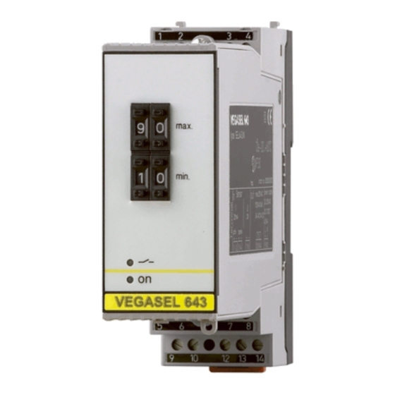
Product description 1 Product description 1.1 Function and configuration VEGASEL 643 auxiliary level switch is a build-in instru- ment with terminal socket, suitable for carrier rail – – mounting (DIN 46 277). Together with a sensor or a max. VEGAMET… signal conditioning instrument it is used –... -
Page 4: Types And Versions
Product description 1.3 Types and versions Level VEGASEL 643 Two-point auxiliary level switch with selectable mode; mode A (overfill protection) or mode B (protection against dry running of pumps) Max. adjustable switching hysteresis Inputs: - passive current input 0/4 … 20 mA - active current input (connections of a sensor 4 …... - Page 5 Functions Mode overfill protection (A) protection against dry running of pumps (B) Adjustments of the inputs 0 … 20 mA or 4 … 20 mA 0 … 10 V or 2 … 10 V VEGASEL 643...
- Page 6 EMVG Emission EN 50 081 - 1 Immission EN 50 082 - 2 EN 61 010 Carrier rail 35 x 7,5 or 35 x 15 acc. to EN 50 022 Transparent cover VEGA 10 11 12 13 14 VEGASEL 643...
-
Page 7: Mounting And Installation Instructions
Never use the bridges with single instrument or at the end of an instrument row. They may come in touch with the operating voltage or cause a shortcircuit. VEGA Instrument coding VEGASEL 643 (pin 4) Direct connection for 0…10 V voltage input 0 … 10 V Direct connection for... -
Page 8: Electrical Connection
VEGA-overvoltage arresters the connection must be made according to the appropriate national installation standards (e.g. in VEGASEL 643 Germany according to VDE-regulations). passive voltage input for connection to the voltage output of a signal conditioning + –... - Page 9 Extension example 2 Instrument 1: VEGAMET 601 or 602 Ex Instrument 2 up to max. instrument 10: VEGASEL 643 each switched to passive voltage input (parallel switching) Note: Current inputs (3, 4) must not be used when the voltage inputs are switched.
-
Page 10: Set-Up
– Terminals voltage input max. 10 Terminals supply and relay output – – min. VEGASEL 643 10 11 12 13 14 Top view, laterally 11 Bar code, series number 12 DIL-switch block 13 Screws 14 Ventilation opening 15 Transparent cover... -
Page 11: Set-Up Sequence
• The auxiliary level switch is hence ready for opera- tion. Please cover with the transparent cover (15). Pre-requirement: VEGASEL 643 auxiliary level switch is connected with a measuring system (sensor and VEGAMET…) or directly with a sensor (4 … 20 mA). - Page 12 60 % of 10 V = 6 V 13,6 mA Switch point 20 % corresponds to 2 V Switch point 60 % corresponds to 6 V The calculation and information examples are valid in the same way for the single point control. VEGASEL 643...
-
Page 13: Diagnosis
Occurring faults, possible reasons and their removals 5.2 Repair are stated under „5.3 Failure removal“. For safety and guarantee reasons repairs on the instrument must only be carried out by VEGA-staff. 5.3 Failure removal Failure Removal / Measure Instrument does not... - Page 14 Notes VEGASEL 643...
- Page 15 Notes VEGASEL 643...
- Page 16 VEGA Grieshaber KG Am Hohenstein 113 D-77761 Schiltach Phone (0 78 36) 50 - 0 Fax (0 78 36) 50 - 201 Fax (0 78 36) 50 - 203 ISO 9001 Technical data subject to alterations 2.19 955 / Sept. 1996...
Need help?
Do you have a question about the VEGASEL 643 and is the answer not in the manual?
Questions and answers