
Subscribe to Our Youtube Channel
Related Manuals for Festo CMMO-ST


Summary of Contents for Festo CMMO-ST
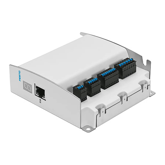
- Page 1 Motor controller CMMO-ST Description Motor controller CMMO-ST-C5-1-DIO 8022056 1301a...
- Page 2 Essential or useful accessories. Information on environmentally sound usage. Text designations: • Activities that may be carried out in any order. 1. Activities that should be carried out in the order stated. – General lists. Festo – GDCP-CMMO-ST-EA-SY-EN – 1301a –...
-
Page 3: Table Of Contents
..........Festo – GDCP-CMMO-ST-EA-SY-EN – 1301a – English... - Page 4 ............. . . Festo – GDCP-CMMO-ST-EA-SY-EN – 1301a – English...
- Page 5 ........... Festo – GDCP-CMMO-ST-EA-SY-EN – 1301a – English...
- Page 6 ..............Festo – GDCP-CMMO-ST-EA-SY-EN – 1301a – English...
- Page 7 CMMO-ST Instructions on this documentation This documentation is intended to help you safely work with the motor controller CMMO-ST. Please note the error correction at page 18 of tis documentation. Product identification, versions The hardware version indicates the version status of the CMMO-ST’s electronics. The firmware version indicates the version status of the operating system.
- Page 8 Requirements for observing the certified UL conditions if the product is operated in the USA or Canada. Operating instructions e.g. for electric cylinder Installing and commissioning the drive type EPCO Tab. 2 Documentation on the CMMO-ST Festo – GDCP-CMMO-ST-EA-SY-EN – 1301a – English...
-
Page 9: Safety And Requirements For Product Use
• Switch off the supply voltage before mounting and installation work. Switch on supply voltage only when mounting and installation work are completely finished. • Never unplug or plug in a product when powered! • Observe the handling specifications for electrostatically sensitive devices. Festo – GDCP-CMMO-ST-EA-SY-EN – 1301a – English... -
Page 10: Intended Use
1.1.2 Intended use The CMMO-ST motor controller is used for controlling stepper motors in accordance with the Festo catalogue, and is especially intended for use with EPCO electric drives. This description documents the basic functions of the CMMO-ST and the I/O interface. -
Page 11: Requirements For Product Use
The product may only be placed in operation by a qualified electrotechnician who is familiar with: – installation and operation of electrical control systems – the applicable regulations for operating safety-engineered systems – the applicable regulations for accident protection and industrial safety – the documentation for the product Festo – GDCP-CMMO-ST-EA-SY-EN – 1301a – English... -
Page 12: Range Of Application And Certifications
– Rules for observing the UL certification can be found in the separate UL special documentation. The technical data stated therein take priority. – The technical data in this documentation may show values deviating from this. Festo – GDCP-CMMO-ST-EA-SY-EN – 1301a – English... -
Page 13: Overview
Higher order controller level: PLC Controller level: CMMO-ST Parameterisation and commissioning level: Drive level: Festo Configuration Tool (FCT) for example Electric cylinder with stepper - or - motor web browser Fig. 2.1 System overview Festo – GDCP-CMMO-ST-EA-SY-EN – 1301a – English... -
Page 14: Overview Of Cmmo-St
– With the integrated web server, using a mechanical drive of the OMS series (optimised motion series): diagnostics and parameterisation via standard web browser, simple positioning section 5.3) – with FCT, the Festo Configuration Tool: convenient, full function range ( section 5.4) Control via Ethernet (CVE): It is possible to start records from a PC programme via the Ethernet interface. -
Page 15: Closed Loop Versus Open-Loop Operation
Overview of CMMO-ST operating modes Records Orders are stored in a record table in CMMO-ST in the form of parameter records. Each record contains all of the information required for a specific function depending on the selected mode. During operation, the higher-order controller (PLC) then makes a successive selection from the records that are saved in the CMMO-ST (“record selection”). -
Page 16: Overview Of Drive Functions
When setting the release (ENABLE), the time set for the switch-on delay starts to run (e.g. 150 ms) and the position controller of the CMMO-ST assumes control of the connected drive. The brake opens simultaneously. The CMMO-ST only accepts positioning jobs after expiration of the switch-on delay. -
Page 17: Comparators & Messages
If the CMMO-ST needs to be replaced, you can simply import the parameter file from the old CMMO-ST into the new CMMO-ST. The new CMMO-ST is then ready for immediate use. An example of creating a parameter backup file with the web server section 5.3.4. -
Page 18: Flash Memory
Overview 2.4.11 Flash memory The integrated FLASH memory of the CMMO-ST includes the parameter files and the firmware. In principle, the number of possible write cycles is limited. Entries are written into the FLASH memory by the following procedures: – teaching with automatic storage ( section 5.5.3) -
Page 19: Number Of Connections
Usable Stroke The distance between the two software limits. Maximum stroke by which the axis can move with the set parameterisation. Festo – GDCP-CMMO-ST-EA-SY-EN – 1301a – English... -
Page 20: Calculation Rules
= AZ + c = REF + a + c Target position/actual position TP, AP = PZ + g = AZ + d + g = REF + a + d + g Festo – GDCP-CMMO-ST-EA-SY-EN – 1301a – English... -
Page 21: Prefix And Direction Of Rotation
– Homing methods to a fixed stop section 2.7.2) – Homing methods to reference switch with/without index section 2.7.3) – Homing method “current position” section 2.7.4) – Automatic homing (valve profile) section 2.7.5) – Movement to zero section 2.7.6) Festo – GDCP-CMMO-ST-EA-SY-EN – 1301a – English... -
Page 22: Homing Methods To A Fixed Stop
If the system does not have a stop (axis of rotation), the homing run will never be com- pleted, i.e. the drive will run continuously at the parameterised search speed. Festo – GDCP-CMMO-ST-EA-SY-EN – 1301a – English... -
Page 23: Homing Methods To Switch With/Without Index Search
3. The drive moves against a stop before a switch is found. In this case, the drive reverses and searches for the switch in the reverse direction. If a switch is found, the drive moves through the complete switching range. Festo – GDCP-CMMO-ST-EA-SY-EN – 1301a – English... -
Page 24: Homing Method "Current Position
This is executed automatically if the drive is not referenced at the start of a position record. The started position record is then executed. The automatic homing run is aborted if the position record input is reset again before the automatic homing run has been executed completely. Festo – GDCP-CMMO-ST-EA-SY-EN – 1301a – English... -
Page 25: Movement To Zero
A complex system of sensors and monitoring functions ensures operational reliability: – Voltage monitoring: detection of undervoltages and overvoltages in the logic and load voltage supply. – Temperature monitoring: output stage and CPU temperature in the CMMO-ST. – I t monitoring/overload protection –... -
Page 26: Safety Aspects
Quick Stop deceleration. As soon as the drive has come to a standstill, the brake output is reset: the brake/clamping unit closes. Simultaneously, the switch-off delay time begins to run. The CMMO-ST still controls the position. The controller end stage is switched off after the switch-off delay. -
Page 27: Mounting
• Observe the IP protection class of the controller and the connectors/cables. Also observe the operating instruction(s) for the drive and the instructions provided with any additional components (e.g. assembly instructions for the cables concerning bending radii or suitability for use with energy chains). Festo – GDCP-CMMO-ST-EA-SY-EN – 1301a – English... -
Page 28: Dimensions Of The Controller
Mounting Dimensions of the controller 108 mm 113 mm 39 mm Fig. 3.1 Dimensions of the controller Festo – GDCP-CMMO-ST-EA-SY-EN – 1301a – English... -
Page 29: Mounting The Controller
Mounting with screws When mounting on the side ( 2 ): To exchange the controller, you only need to loosen the 3 screws by a few rotations, after which the controller can be tilted out. Festo – GDCP-CMMO-ST-EA-SY-EN – 1301a – English... -
Page 30: H-Rail Mounting
• by inserting the top into the hooks in the clip first, then • press the H-rail downwards until the CMMO clicks into place. max. 5 mm H-rail clip Maximum screw-in depth Fig. 3.3 H-rail mounting Festo – GDCP-CMMO-ST-EA-SY-EN – 1301a – English... -
Page 31: Electrical Installation
The project engineering performance data relates to a maximum cable length of 10 m. To ensure compliance with the IP protection class (if required): • Please note that the specified IP protection class is only achieved with a full plug and cable assignment. Festo – GDCP-CMMO-ST-EA-SY-EN – 1301a – English... - Page 32 – NEBM-S1W9-E-…-Q5: for motors with 9-pin plug – NEBM-M12G8-E-…-Q5: for size 28 motors 1) Specifications status August 2012. Only the current specifications in the Festo catalogue are relevant: www.festo.com Tab. 4.1 Overview of cables (accessories) Festo – GDCP-CMMO-ST-EA-SY-EN – 1301a – English...
-
Page 33: Power Supply [X9]
Electrical installation Observe the tightening torques specified in the documentation for the cables and plugs used. The assortment of plugs supplied with the CMMO-ST is also available under the type code NEKM-C-10. Power supply [X9] Port Function – Do not connect! –... -
Page 34: Functional Earth
Technical data of the voltage supply: ( appendix A.1). Functional earth The metal sub-base of the CMMO-ST is used as a functional earth. It is galvanically isolated from the power supply and, among other things, ensures EMC safety. Note • Connect the metal sub-base of the CMMO-ST to the earth potential with low impedance (short cable with large cross section). -
Page 35: I/O Interface [X1]
Damage to the device Pin 24 and pin 25 are not short circuit proof. The functional description of the I/O interface, dependent on the selected profile, can be found in the Commissioning chapter. Festo – GDCP-CMMO-ST-EA-SY-EN – 1301a – English... -
Page 36: Electrical Specifications Of [X1]
(depending on switch type). Reference potential Tab. 4.5 Connection X1A reference switch The types listed in the Festo catalogue for the respective drive are suitable for use as reference switches ( www.festo.com). Festo – GDCP-CMMO-ST-EA-SY-EN – 1301a – English... -
Page 37: Sto [X3]
Diagnostics 1 The diagnostic contacts are potential-free. The diagnostic contact is low Diagnostics 2 impedance if the STO function has been requested and activated via two channels. Tab. 4.6 Connection X3 STO Festo – GDCP-CMMO-ST-EA-SY-EN – 1301a – English... -
Page 38: Encoder [X2]
String B/ Connection of the holding brake Short circuit and overload-proof. 24 V, max. 1.4 A 33 W. BR– BR– = GND, BR+ is switched (24 V load) Tab. 4.8 Connection X6 motor Festo – GDCP-CMMO-ST-EA-SY-EN – 1301a – English... -
Page 39: Commissioning
Unexpected movement of the drive due to incorrect or incomplete parametrisation! When the CMMO-ST is switched on, the I/O control interface is activated as standard. • Make sure that there is no active ENABLE signal when switching on the CMMO-ST on the I/O control interface. - Page 40 Commissioning Note The CMMO-ST does not carry out any positioning jobs/records if it is not referenced. • Carry out a homing run in the following cases to anchor the measuring reference system to the reference point: – every time the logic voltage supply is switched on or after every failure –...
-
Page 41: Ethernet Interface (Rj-45)
255.255.255.0. A gateway is not assigned. Additional configuration options DHCP client The CMMO-ST can also be configured as a DHCP client. It then obtains its IP address from a DHCP server in your network. Specifying a fixed IP address Alternatively you can also assign a fixed IP address to the CMMO-ST. -
Page 42: Safety In The Network
5.2.4 Timeout The CMMO-ST detects if the connection to the FCT software has been interrupted and it behaves in accordance with the settings parameterised in FCT under “Error management” (error number 0x32). The timeout period is typically 1 s, but it can be longer in slow networks, as the timeout period is dynamically adapted to the transmission rate. -
Page 43: Initial Start-Up Via Ethernet
5.2.5 Initial start-up via Ethernet The CMMO-ST will need to be connected directly to a computer/laptop for the initial start-up phase. The CMMO-ST cannot be connected immediately to a network during the initial start-up phase, as its active DHCP server could result in network malfunctions. -
Page 44: Commissioning Via Web Server
Parameter files Uploading and downloading parameter files for initial start-up or for use as backup files. Homing Starting a homing run in accordance with the homing method parameterised in the CMMO-ST (default settings: Tab. 5.2). The homing run can only be started; a change of the homing method must take place in FCT. - Page 45 1) The maximum values for speed, acceleration, force, etc. depend on the mechanical system used and can be read via FCT if required. Tab. 5.2 Valve profile: default values (EPCO) All other settings of the parameter files can be read in FCT as needed. Festo – GDCP-CMMO-ST-EA-SY-EN – 1301a – English...
-
Page 46: Initial Start-Up With The Web Server
Commissioning 5.3.3 Initial start-up with the web server If you have accessed the CMMO-ST website in accordance with section 5.2.5, you will initially be presented with the diagnostics page: Fig. 5.2 Website: diagnostics Festo – GDCP-CMMO-ST-EA-SY-EN – 1301a – English... - Page 47 2. Enter the type code of your EPCO drive in the uppermost text box in accordance with the rating plate, and click <Search> to download a suitable parameter file from the Festo website (Internet access required). Caution: Incomplete entry of the code may result in malfunctions, uncontrolled behaviour and damage.
- Page 48 Fig. 5.10 Teach 11.Move to a different position and teach this position to position record no. 2. 12.Enter the additional positions. Relative target positions can be entered by hand, but they cannot be taught. Festo – GDCP-CMMO-ST-EA-SY-EN – 1301a – English...
- Page 49 Commissioning Fig. 5.11 Website: Parameters – Record Sets (1) 13.Adjust the values for travel speed, acceleration and force limit. Fig. 5.12 Website: Parameters – Record Sets (2) Festo – GDCP-CMMO-ST-EA-SY-EN – 1301a – English...
-
Page 50: Creating A Parameter Backup File
When parameterisation is complete you can create a backup copy of your parameters by using the web browser. If you ever need to replace the CMMO-ST, you can import this parameter file into the new CMMO-ST. Re-parameterisation is therefore no longer required. -
Page 51: Commissioning With Fct (Festo Configuration Tool)
– A framework as program start and entry point with uniform project and data management for all supported device types. – A plug-in for the special requirements of each device type (e.g. CMMO-ST) with the necessary descriptions and dialogues. The plug-ins are managed and started from the framework. -
Page 52: Starting The Fct
– or – In the Windows menu [Start], select the entry [Festo Software] [Festo Configuration Tool]. 3. Create a project in the FCT or open an existing project. Add a CMMO-ST to the project: menu [Components] [Insert]. Instructions on parameterising and commissioning... - Page 53 FCT help ...(FCT installation directory)\Help\ – FCT_de.pdf (framework) PlugIn help ...(FCT installation directory)\HardwareFamilies\ – CMMO-ST_de.pdf (CMMO-ST) Festo\CMMO-ST\V...\Help\ In order to use the printed version in Adobe PDF format, you will require Adobe Reader. Festo – GDCP-CMMO-ST-EA-SY-EN – 1301a – English...
-
Page 54: I/O Interface
I/O interface 5.5.1 Profiles for selection Two profiles are available for control of the CMMO-ST via the I/O interface: Valve profile (7) The valve profile is based on the control of pneumatic valves and is very easy to configure. Use this profile if 7 position records are sufficient (simple positioning operation only). -
Page 55: Properties Of The Valve Profile (7)
Automatic homing A homing run can be executed automatically in the valve profile if the drive is not referenced at the start of a position record, section 2.7.5. Festo – GDCP-CMMO-ST-EA-SY-EN – 1301a – English... - Page 56 (prevention of brake wear as a result of faulty application). ENABLE After setting this enable signal the CMMO-ST assumes control of the connected drive. RESET A reported error is reset (if possible).
- Page 57 (e.g. load voltage is present, ENABLE is set, no serious error). Torque Limit reached The parameterised torque/force limit has been reached. Tab. 5.4 Valve profile: Assignment of outputs Electrical specification of the inputs and outputs: section 4.4.1. Festo – GDCP-CMMO-ST-EA-SY-EN – 1301a – English...
- Page 58 1) Valve profile: Switching on, homing Pos1 Pos2 ENABLE RESET Ready Referenced OnPos1 OnPos2 >1s ENABLE Homing run ended Start homing Reset REF Fig. 5.16 Timing diagram: Valve profile – switching on, homing Festo – GDCP-CMMO-ST-EA-SY-EN – 1301a – English...
- Page 59 Start homing via REF input. Homing run ended Following successful completion of the homing run the Referenced output is set. Reset REF The REF input may only be reset after successful completion of the homing run. Festo – GDCP-CMMO-ST-EA-SY-EN – 1301a – English...
- Page 60 Pos1 Pos2 ENABLE RESET Ready Referenced OnPos1 OnPos2 Start record 1 Start record 2 Cancel record 1 Destination 2 reached Fig. 5.17 Timing diagram: Valve profile – terminate record 1, start record 2 Festo – GDCP-CMMO-ST-EA-SY-EN – 1301a – English...
- Page 61 Start record 2 Record 2 is started by setting input Pos2. Destination 2 reached After reaching the parameterised target position window and after expiration of the parameterised damping time, the output OnPos2 is set. Festo – GDCP-CMMO-ST-EA-SY-EN – 1301a – English...
- Page 62 Commissioning 3) Valve profile: Record switching Pos1 Pos2 ENABLE RESET Ready Referenced OnPos1 OnPos2 Start record 1 Destination 2 reached Switching Fig. 5.18 Timing diagram: Valve profile – record switching Festo – GDCP-CMMO-ST-EA-SY-EN – 1301a – English...
- Page 63 While record 1 is being executed, input Pos2 is set. The drive switches immediately to record 2. Destination 2 reached After reaching the parameterised target position window and after expiration of the parameterised damping time, the output OnPos2 is set. Festo – GDCP-CMMO-ST-EA-SY-EN – 1301a – English...
- Page 64 4) Valve profile: Acknowledging errors Pos1 Pos2 ENABLE RESET Ready Referenced OnPos1 OnPos2 Start record 1 Restart record 1 Error Destination 1 reached Acknowledge error Fig. 5.19 Timing diagram: Valve profile – acknowledging errors Festo – GDCP-CMMO-ST-EA-SY-EN – 1301a – English...
- Page 65 When the input Pos1 has been reset, record 1 can be restarted by setting this input again. Destination 1 reached After the parameterised target position window is reached and the parameterised damping time has expired, the output OnPos1 is set. Festo – GDCP-CMMO-ST-EA-SY-EN – 1301a – English...
-
Page 66: Properties Of The Binary Profile (31)
Pause (intermediate stop) An “intermediate stop” is triggered on the CMMO-ST via the I/O interface. This works as follows: 1. If the signal at digital input no. 7 “PAUSE” is removed during a record (= physical 0 signal), the drive brakes at the braking ramp that has been parameterised for this record and remains stationary. - Page 67 Acknowledge error - or - delete remaining path (if a position record has been interrupted with input 7). Tab. 5.5 Binary profile: Inputs … 31 … … … … … Tab. 5.6 Binary coding of the records Festo – GDCP-CMMO-ST-EA-SY-EN – 1301a – English...
- Page 68 The drive is ready for operation. Torque limit reached Target force reached. Only for positioning and speed mode. 1) The output is inverted, i.e. the message is issued through logic 0. Tab. 5.7 Binary profile: Outputs Festo – GDCP-CMMO-ST-EA-SY-EN – 1301a – English...
- Page 69 1) Switching on, homing RECORD ENABLE PAUSE START RESET Ready Referenced Error Pause >1s PAUSE Reset START ENABLE Homing run ended Start homing Fig. 5.20 Timing diagram: Binary profile – switching on, homing Festo – GDCP-CMMO-ST-EA-SY-EN – 1301a – English...
- Page 70 After the outputs Ack and MC have been reset, the START input can also be reset again. Homing run ended Following successful completion of the homing run, the outputs MC and Referenced are set. Festo – GDCP-CMMO-ST-EA-SY-EN – 1301a – English...
- Page 71 Ready Referenced Error Halt Record 1 PAUSE Pre-select record 3 Delete remaining path Start record 3 Drive is ready Record 1 Fig. 5.21 Timing diagram: Binary profile – switch, pause, delete remaining path Festo – GDCP-CMMO-ST-EA-SY-EN – 1301a – English...
- Page 72 MC is set (MC = 1). Drive is ready Set the input PAUSE again. The outputs Pause and Ready are also set again. The drive is ready to ac- cept new orders. Festo – GDCP-CMMO-ST-EA-SY-EN – 1301a – English...
- Page 73 Commissioning 3) Acknowledging errors RecNr ENABLE HALT START RESET Ready Referenced Error Halt Start record Acknowledge error Error Restart Fig. 5.22 Timing diagram: Binary profile – acknowledging errors Festo – GDCP-CMMO-ST-EA-SY-EN – 1301a – English...
- Page 74 After setting this input the parameterised time for the switch-on delay of the holding brake starts to run. When this time has expired the outputs Ready and Error are set again. Restart The record is restarted with a START signal and it travels the remaining path. Festo – GDCP-CMMO-ST-EA-SY-EN – 1301a – English...
- Page 75 Commissioning 4) Jogging ENABLE HALT START Jog- - Jog+ RESET Ready Referenced Error Halt Start jogging End jogging Fig. 5.23 Timing diagram: Binary profile – jogging Festo – GDCP-CMMO-ST-EA-SY-EN – 1301a – English...
- Page 76 After the input Jog– has been set, the drive starts moving in a negative direction. Motion complete (MC) is reset. End jogging When the jogging signal is removed the drive brakes and remains stationary. MC is set upon expiration of the MC damping time. Festo – GDCP-CMMO-ST-EA-SY-EN – 1301a – English...
-
Page 77: Structure Of The Records In The Record Table
Comments (max. 32 characters per record) Applied load (linear axis: workpiece mass; axis of rotation: inertia) Other CVE objects: #31 record number preselection; #141 current record number Tab. 5.8 Parameters for record table in positioning mode Festo – GDCP-CMMO-ST-EA-SY-EN – 1301a – English... - Page 78 The drive continues to run with the end speed of the position record in a speed-controlled manner. The speed is not monitored (speed regulation, but no monitoring of the deviation). The force is limited to the maximum value defined in the position record. Festo – GDCP-CMMO-ST-EA-SY-EN – 1301a – English...
-
Page 79: Speed Mode (Binary Profile Only)
– In open-loop operation: As long as no other drive function is executed, the drive will continue to run with the parameterised current. Stroke limitation remains active. Deviations from the nominal speed are not detected. Festo – GDCP-CMMO-ST-EA-SY-EN – 1301a – English... -
Page 80: Force Mode (Only In Binary Profile)
Applied load (linear axis: workpiece mass; axis of rotation: inertia) Other CVE objects: #31 record number preselection; #141 current record number. 1) These parameters always have a positive prefix. Tab. 5.10 Parameters for record table in force mode Festo – GDCP-CMMO-ST-EA-SY-EN – 1301a – English... -
Page 81: Record Switching By Plc (Binary Profile)
– Delay: The current record is completed. The subsequent record addressed by the START signal is started after the current record has ended (immediately after the MC signal). – Interrupt: The current record is interrupted immediately and the newly addressed record is executed directly. Festo – GDCP-CMMO-ST-EA-SY-EN – 1301a – English... -
Page 82: Record Linking (Binary Profile Only)
Waiting time in [ms]: The time between the appearance of Motion Complete (MC) for a record with record linking and the start of the subsequent positioning record. Number of the subsequent record Feedback Via the MC signal to the I/O interface. Tab. 5.11 Parameters for record linking Festo – GDCP-CMMO-ST-EA-SY-EN – 1301a – English... -
Page 83: Comparators
“–50 mm” must be entered as the minimum value and “–40 mm” as the maximum value. Tab. 5.12 Parameters for position comparators The position limits are always specified in absolute values, even for relative position records. Festo – GDCP-CMMO-ST-EA-SY-EN – 1301a – English... -
Page 84: Speed Comparators
1) The limit values can be both positive and negative. The prefix here indicates the direction of the force. If the minimum value is greater than the maximum value, the condition for the force comparator is never fulfilled. Tab. 5.14 Parameters for force comparators Festo – GDCP-CMMO-ST-EA-SY-EN – 1301a – English... -
Page 85: Time Comparators
1) The limit values can only be positive. If the minimum value is greater than the maximum value, the condition for the time comparator is never fulfilled. Tab. 5.15 Parameters for time comparators Festo – GDCP-CMMO-ST-EA-SY-EN – 1301a – English... -
Page 86: Instructions On Operation
FCT online help for the plug-in). This password is also valid for the web browser. Maintenance and care CMMO-ST motor controllers are maintenance-free. However, follow the maintenance instructions for the drive and the additional components. Disposal and environment Note •... -
Page 87: Diagnostics
“Search” button in the “FCT Interface” dialogue window to start the “Festo Device Tool”. Then use the context menu of the CMMO-ST that has been located by the network scan to select the option “Identification On/Off ”. - Page 88 7-segment display, it may be the case that not all malfunctions are displayed. Read out the dia- gnostic memory to display all messages. Festo – GDCP-CMMO-ST-EA-SY-EN – 1301a – English...
-
Page 89: Diagnostic Memory
If the memory is full, the oldest element will be overwritten (ring buffer). Fig. 6.3 Diagnostic memory in FCT The diagnostic memory can also be read via the CMMO-ST website ( section 5.3): Fig. 6.4 Diagnostic memory on the website Deleting the diagnostic memory You can erase the diagnostic memory via FCT. -
Page 90: Malfunctions: Causes And Remedy
Restart controller” in the FCT menu. Error reaction(s) The list of error responses can be found in section 6.4.1. The factory setting is in bold. You can parameterise the error messages in FCT (“Error Management” panel). Festo – GDCP-CMMO-ST-EA-SY-EN – 1301a – English... - Page 91 An error has occurred during evaluation of the encoder. The current position values may be incorrect. • Conduct a software reset with a commutation angle search and homing procedure. – Acknowledgement option: Cannot be acknowledged, software reset required. Parameterisable error response(s): A Festo – GDCP-CMMO-ST-EA-SY-EN – 1301a – English...
- Page 92 Inspection with the trace function in FCT (active current actual value). – Acknowledgement option: Cannot be acknowledged, software reset required. Parameterisable error response(s): A Festo – GDCP-CMMO-ST-EA-SY-EN – 1301a – English...
- Page 93 Movements in a negative direction are blocked. – Acknowledgement option: Error can only be acknowledged after eliminating the cause. Parameterisable error response(s): A, B, C, E, F Festo – GDCP-CMMO-ST-EA-SY-EN – 1301a – English...
- Page 94 • If the error is still present after a reset has been conducted, it means there is an internal defect and the device has to be replaced. – Acknowledgement option: Error can be acknowledged. Parameterisable error response(s): A, B Festo – GDCP-CMMO-ST-EA-SY-EN – 1301a – English...
- Page 95 – For parameterisation as an error: The error can be acknowledged. Parameterisable error response(s): A – For parameterisation as a warning: The warning disappears if the load voltage is back within the permissible range. Festo – GDCP-CMMO-ST-EA-SY-EN – 1301a – English...
- Page 96 The error may be caused by the actual velocity or the actual acceleration being too high at the switching point. – Acknowledgement option: Error can only be acknowledged after eliminating the cause. Parameterisable error response(s): A Festo – GDCP-CMMO-ST-EA-SY-EN – 1301a – English...
- Page 97 • During download of a parameter file: Does the version of the parameter file fit the firmware version? If the error continues to occur, please contact Festo Service – Acknowledgement option: Error can only be acknowledged after eliminating the cause.
- Page 98 • Ascertain the version of your hardware. You can ascertain the compatible firmware versions and download the appropriate firmware from the Festo website. – For parameterisation as an error: The error can only be acknowledged after eliminating the cause.
- Page 99 • Check parameterisation of the downtime window. – For parameterisation as a warning: The warning disappears if the actual position is within the standstill window again or a new record has been started. Festo – GDCP-CMMO-ST-EA-SY-EN – 1301a – English...
- Page 100 The start-up event does not occur if the preceding entry in the diagnostic memory has already been a start-up event. • This event is only used for improved documentation of the malfunctions. Festo – GDCP-CMMO-ST-EA-SY-EN – 1301a – English...
- Page 101 There is no longer a connection to the FCT, e.g. the cable was disconnected. • Check the connection and perform a reset if necessary. – For parameterisation as a warning: The warning disappears if the connection to the FCT is re-established. Festo – GDCP-CMMO-ST-EA-SY-EN – 1301a – English...
- Page 102 • Enter a valid parameter set in the device. – For parameterisation as a warning: The warning disappears if a new parameter file is successfully written. Tab. 6.3 Table of error messages Festo – GDCP-CMMO-ST-EA-SY-EN – 1301a – English...
-
Page 103: Problems With The Ethernet Connection
• Check whether the devices are accessible in the same subnet. Contact your network adminis- trator if necessary. • You can also use the Ping program to determine whether the CMMO-ST is accessible in the network. For Windows XP/Windows 7: •... - Page 104 Diagnostics If the IP address of the CMMO-ST is unknown or if you need to change the network settings of the CMMO-ST You can run a network scan by using the FCT plug-in for the CMMO-ST. See menu [Component] [FCT Interface] [“Search…” button].
-
Page 105: Other Problems And Remedies
FCT plug-in for the correct settings of the controller parameters. • Error in the power supply. Observe the tolerance values in accordance with the chapter “Technical data”. Tab. 6.4 Other problems and remedies Festo – GDCP-CMMO-ST-EA-SY-EN – 1301a – English... -
Page 106: Malfunction "Index Pulse Too Close On Proximity Sensor" (2Eh)
2. Then move the proximity sensor a few tenths of a mm up to several millimetres (depending on axis type). Switching range of the proximity sensor Recommended position: centrally between Index pulse two index pulses Festo – GDCP-CMMO-ST-EA-SY-EN – 1301a – English... -
Page 107: Technical Appendix
Key safety data and certifications can be found in the separate STO documentation for the CMMO-ST. Requirements for observing the certified UL conditions if the product is operated in the USA or Canada can be found in the separate special UL documentation. Festo – GDCP-CMMO-ST-EA-SY-EN – 1301a – English... - Page 108 In open-loop operation (i.e. without an encoder) the controller uses the same resolution. Maximum speed and torque of the operating instructions for the drives used, motors e.g. type EPCO. Festo – GDCP-CMMO-ST-EA-SY-EN – 1301a – English...
-
Page 109: B Control Via Ethernet (Cve)
(client-server principle). The TCP connection is typically established once and remains in effect for as long as communication is required with the CMMO-ST. If the drive is in motion when the connection is ended, a Quick Stop func- tion is triggered. -
Page 110: Cve Protocol
Each object has one of the data types listed in Tab. B.1. The byte order is little endian. Read object In order to read a CVE object, a request must be sent to the CMMO-ST in accordance with Tab. B.2. This sends back a response Tab. B.3. - Page 111 0x0D 0x0E Object index UINT16 Index of the CVE object to be read. 0x0F 0x10 Object subindex UINT08 Always 0 0x11 Reserved UINT08 Placeholder (initialise with 0). Tab. B.2 Request “Read CVE object” Festo – GDCP-CMMO-ST-EA-SY-EN – 1301a – English...
- Page 112 Data type UINT08 Data type of the CVE object. 0x12 Data byte 1 corresponding Object value to data type of … Data byte K the CVE object Tab. B.3 Response “Read CVE object” Festo – GDCP-CMMO-ST-EA-SY-EN – 1301a – English...
- Page 113 Data type of the CVE object to be written. 0x12 Data byte 1 corresponding Object value to data type of … Data byte K the CVE object Tab. B.4 Request “Write CVE object” Festo – GDCP-CMMO-ST-EA-SY-EN – 1301a – English...
- Page 114 Data type of the written CVE object. If an attempt has been made to write an object with an invalid data type, the correct data type is returned here. Tab. B.5 Response “Write CVE object” Festo – GDCP-CMMO-ST-EA-SY-EN – 1301a – English...
- Page 115 The CVE object cannot be written, as the Correct the data type. specified data type is incorrect. 0xAD The CVE object cannot be written, as it is Remove password protection via FCT. password protected. Tab. B.6 Confirmation (acknowledge) Festo – GDCP-CMMO-ST-EA-SY-EN – 1301a – English...
-
Page 116: Controlling The Drive
B.1.3 Controlling the drive The CMMO-ST has a finite state machine that executes the operating modes of the drive in accordance with the user’s specifications. Fig. B.1 shows the possible states. These are described in detail in Tab. B.7. Tab. B.8 shows the possible transitions between the states. - Page 117 Fig. B.1 Finite state machine of the CMMO-ST Festo – GDCP-CMMO-ST-EA-SY-EN – 1301a – English...
- Page 118 (e.g. via the fieldbus). After executing the startup code the machine automatically reverts to status B. Not ready to In this status CMMO-ST self tests are carried out. The output Closed switch on stage remains switched off.
- Page 119 Ready to switch on CW.QS (Quick Stop) = 1 CW.EV (Enable Voltage) = 1 CW.SO (Switch on) = 0 Operation enabled CW.FR (Error Reset) = 0 Switch on disabled CW.EV (Enable Voltage) = 0 Festo – GDCP-CMMO-ST-EA-SY-EN – 1301a – English...
- Page 120 CW.SO (Switch on) = 1 Ready to switch on CW.FR (Error Reset) = 0 Operation enabled CW.EO (Enable Operation) = 1 CW.QS (Quick Stop) = 1 CW.EV (Enable Voltage) = 1 CW.SO (Switch on) = 1 Festo – GDCP-CMMO-ST-EA-SY-EN – 1301a – English...
- Page 121 Start Must always be 0. CW.PSOn Power stage on after reset (Output stage on after error reset) CW.FR Error reset CW.STP STOP 9 … 31 Must always be 0. Tab. B.9 Control word Festo – GDCP-CMMO-ST-EA-SY-EN – 1301a – English...
- Page 122 Referenced. The drive is referenced. SW.DPB Direction positive blocked. The drive cannot be moved in a positive direction. SW.DNB Direction negative blocked. The drive cannot be moved in a negative direction. Tab. B.10 Status word Festo – GDCP-CMMO-ST-EA-SY-EN – 1301a – English...
- Page 123 STO input (i.e. CVE object #358 exhibits value 255). Nothing is connected to the I/O interface of the CMMO-ST. The “Switch on disabled” status is active; the status word exhibits the value 0x00800440. 1. Activate the higher-order controller for the CVE connection by writing the value 2 into CVE object #3.
-
Page 124: Explanation Of Increments
Parameterise the drive completely in FCT and then read objects #218 “Unit of measure- ment” and #217 “Power of ten”. EXAMPLE: #218 = 1, i.e. Metre –6 #217 = –6, i.e. 10 1 mm = 1000 SINC Festo – GDCP-CMMO-ST-EA-SY-EN – 1301a – English... -
Page 125: List Of Cve Objects
Error with top priority acknowledgement ability Error handler Warning with top priority Error handler Power of ten conversion factor Drive functions Unit of measurement conversion factor Drive functions Current target position Drive functions Hardware enable System Festo – GDCP-CMMO-ST-EA-SY-EN – 1301a – English... - Page 126 0x03 Web server The master control may be changed by an interface that does not have this only if it is not blocked via object #4 Block master control. Values: 0 … 255 Festo – GDCP-CMMO-ST-EA-SY-EN – 1301a – English...
- Page 127 Default: 1 Actual force System SINT16 R/-/-/-/- Current actual force in one-tenth of one percent of the maximum motor current (calculated from the measured current) Unit: ‰ Values: –32768 … 32767 Default: 0 Festo – GDCP-CMMO-ST-EA-SY-EN – 1301a – English...
- Page 128 Actual acceleration System SINT32 R/-/-/-/- Current, calculated actual acceleration Unit: SINC/s² Values: –2147483648 … 2147483647 Default: 0 Nominal acceleration System SINT32 R/-/-/-/- Current nominal acceleration Unit: SINC/s² Values: –2147483648 … 2147483647 Default: 0 Festo – GDCP-CMMO-ST-EA-SY-EN – 1301a – English...
- Page 129 0: No operating mode selected 1: Positioning mode 3: Speed mode 4: Force mode/torque mode 6: Homing mode –3: Jog positive –4: Jog negative Values: 0, 1, 3, 4, 6, –3, –4 Default: 0 Festo – GDCP-CMMO-ST-EA-SY-EN – 1301a – English...
- Page 130 0xFFFF means that no warning is present. Values: 0 … 65535 Default: 65535 #217 Power of ten conversion factor Drive functions SINT08 R/W1/-/-/- Example in section B.2 Unit: 10 Values: < 0 Default: 0 Festo – GDCP-CMMO-ST-EA-SY-EN – 1301a – English...
- Page 131 Bits 1 … 7: reserved Only if all bits are 1 can the finite state machine be switched to the status “Operation enabled” through the control word. Unit: Bit field Values: 0 … 255 Default: 254 Festo – GDCP-CMMO-ST-EA-SY-EN – 1301a – English...
-
Page 132: C Glossary
CMMO-ST if the cause has been eliminated beforehand). Auto MDI(X) In the network cable between the CMMO-ST and your computer, the individual wires between the two RJ-45 plugs can be connected in a straight or cross-over configuration. This is detected automatically. MDI = Medium Dependent Interface. - Page 133 (dependent on the operating mode). Reference point section 2.6 (= REFerence point) Software limit Overview of measuring reference system section 2.6 Teach mode Overview of drive functions section 2.4.2 Tab. C.1 Product-specific terms and abbreviations Festo – GDCP-CMMO-ST-EA-SY-EN – 1301a – English...
- Page 134 Copyright: Festo AG & Co. KG Postfach D-73726 Esslingen Phone: +49 711 347-0 Fax: +49 711 347-2144 e-mail: service_international@festo.com Reproduction, distribution or sale of this document or communica- Internet: tion of its contents to others without express authorization is www.festo.com prohibited.
Need help?
Do you have a question about the CMMO-ST and is the answer not in the manual?
Questions and answers