baltur SPARK 18 DSGW Manual Instructions For Use
Hide thumbs
Also See for SPARK 18 DSGW:
- Instruction manual (55 pages) ,
- Instructions manual (56 pages)
Table of Contents
Advertisement
Available languages
Available languages
EN
Manual instructions for use
Manuale
istruzioni per l'uso
SP
Manual de instrucciones
SPARK 18 DSGW
SPARK 26 DSG / DSGW
SPARK 35 DSG / DSGW
FR
Notice d'instructions
ISTRUZIONI ORIGINALI (IT)
ORIGINAL INSTRUCTIONS ARE (IT)
INSTRUCCIONES ORIGINALES (IT)
ISTRUCTIONS ORIGINALES (IT)
PL
Instrukcja obsługi
0006080404_201711
Advertisement
Table of Contents

Related Manuals for baltur SPARK 18 DSGW


Summary of Contents for baltur SPARK 18 DSGW
- Page 1 Instrukcja obsługi Manual de instrucciones Notice d'instructions Manual instructions for use Manuale istruzioni per l'uso SPARK 18 DSGW SPARK 26 DSG / DSGW SPARK 35 DSG / DSGW ISTRUZIONI ORIGINALI (IT) ORIGINAL INSTRUCTIONS ARE (IT) INSTRUCCIONES ORIGINALES (IT) ISTRUCTIONS ORIGINALES (IT)
-
Page 3: Table Of Contents
SOMMARIO AVVERTENZE PER L'USO IN CONDIZIONI DI SICUREZZA ........................5 CARATTERISTICHE TECNICHE ................................8 APPLICAZIONE DEL BRUCIATORE ALLA CALDAIA ..........................12 IMPIANTO DI ALIMENTAZIONE CON POMPA AS 47 ..........................13 IMPIANTO DI ALIMENTAZIONE CON POMPA AS 67 ..........................14 APPARECCHIATURA DI COMANDO E CONTROLLO LMO......................15 PREPARAZIONE PER L’ACCENSIONE ..............................17 ACCENSIONE E REGOLAZIONE ................................17 USO DEL BRUCIATORE ...................................17... - Page 4 DICHIARAZIONE DI CONFORMITÀ CE0085: DVGW CERT GmbH, Josef-Wirmer Strasse 1-3-53123 Bonn (D) Dichiariamo che i nostri bruciatori ad aria soffiata di combustibili luquidi, gassosi e misti, domestici e industriali, serie: BPM...; BGN…; BT…; BTG…; BTL…; TBML...; Comist…; GI…; GI…Mist; Minicomist…; PYR…; RiNOx…; Spark...; Sparkgas...; TBG...;TBL...; TS…;...
-
Page 5: Avvertenze Per L'uso In Condizioni Di Sicurezza
AVVERTENZE PER L'USO IN CONDIZIONI DI persone (bambini compresi) le cui capacità fisiche, sensoriali o mentali siano ridotte, oppure con mancanza di esperienza o di SICUREZZA conoscenza. • l'uso dell'apparecchio è consentito a tali persone solo nel caso SCOPO DEL MANUALE in cui possano beneficiare, attraverso l'intermediazione di una Il manuale si propone di contribuire all'utilizzo sicuro del prodotto a cui persona responsabile, di informazioni relative alla loro sicurezza,... - Page 6 • In caso di guasto e/o di cattivo funzionamento dell’apparecchio, effettuare da personale professionalmente qualificato le seguenti disattivarlo, astenendosi da qualsiasi tentativo di riparazione operazioni: o di intervento diretto. Rivolgersi esclusivamente a personale - Tarare la portata di combustibile del bruciatore secondo la professionalmente qualificato.
- Page 7 Avvertenze particolari per l’uso del gas. terra. In caso di controllo della corrente di ionizzazione con neutro • Verificare che la linea di adduzione e la rampa siano conformi alle non a terra è indispensabile collegare tra il morsetto 2 (neutro) e la norme e prescrizioni vigenti.
-
Page 8: Caratteristiche Tecniche
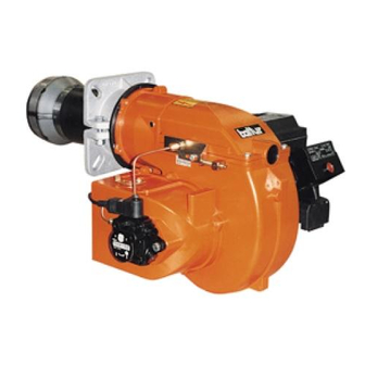
CARATTERISTICHE TECNICHE SPARK SPARK SPARK SPARK SPARK 26 DSG 35 DSG DSGW DSGW DSGW Portata Kg/h Kg/h 18,0 Potenza termica Pressione pompa Motore 230V-50Hz 250 W 370 W Viscosità max. combustibile (gasolio) 1,5° E - a/at 20° C Alimentaz. elettrica 1N 230V - 50Hz Trasformatore 10kV - 20mA - 230V - 50Hz... - Page 9 SPARK 18 DSGW SPARK 26 DSGW SPARK 35 DSGW SPARK 26DSG SPARK 35DSG Pompa gasolio Apparecchiatura Pulsante sblocco Motore ventola Interruttori manuali Connettori Trasformatore d’accensione Fotoresistenza Visore fiamma 10.1) Servomotore serr. aria Testa di combustione Guarnizione isolante Flangia attacco bruciatore...
- Page 10 DIMENSIONI MOD. Ø Ø SPARK 18 DSGW 450 220 230 355 262.5 92.5 710 105 300 117 114 170 200 M10 135 SPARK 26 DSG 450 220 230 355 262.5 92.5 710 105 300 139 114 170 200 M10 150...
- Page 11 CAMPO DI LAVORO I campi di lavoro sono ottenuti su caldaie di prova rispondenti alla norma EN267 e sono orientativi per gli accoppiamenti bruciatore-caldaia. Per il corretto funzionamento del bruciatore le dimensioni della camera di combustione devono essere rispondenti alla normativa vigente; in caso contrario vanno consultati i costruttori.
-
Page 12: Applicazione Del Bruciatore Alla Caldaia
APPLICAZIONE DEL BRUCIATORE ALLA CALDAIA Il bruciatore è dotato di flangia attacco scorrevole sulla testa di combustione. I componenti a corredo vanno montati come da disegno. Anello lamiera Cordone isolante Flangia isolante Flangia in alluminio Quando si applica il bruciatore alla caldaia occorre posizionare correttamente detta flangia affinché la testa di combustione penetri nel focolare nella quantità... -
Page 13: Impianto Di Alimentazione Con Pompa As 47
IMPIANTO DI ALIMENTAZIONE CON POMPA AS 47 IMPIANTO DI ALIMENTAZIONE PER GRAVITA’ 1 Serbatoio combustibile Tubo di aspirazione 2 Tubazione di alimentazione Tubo di ritorno del bruciatore 3 Filtro a rete Dispositivo automatico intercettazione 4 Bruciatore a bruciatore fermo 5 Degasificatore Valvola unidirezionale L. -
Page 14: Impianto Di Alimentazione Con Pompa As 67
IMPIANTO DI ALIMENTAZIONE CON POMPA AS 67 IMPIANTO DI ALIMENTAZIONE PER GRAVITA’ 1 Serbatoio combustibile Tubo di aspirazione 2 Tubazione di alimentazione Tubo di ritorno del bruciatore 3 Filtro a rete Dispositivo automatico intercettazione 4 Bruciatore a bruciatore fermo 5 Degasificatore Valvola unidirezionale L. -
Page 15: Apparecchiatura Di Comando E Controllo Lmo
APPARECCHIATURA DI COMANDO E CONTROLLO A MICROPROCESSORE CON FUNZIONAMENTO INTERMITTENTE. LMO... Funzionamento Il pulsante di sblocco «EK...» è l’elemento principale per poter accedere a tutte le funzioni di diagnostica (attivazione e disattivazione), oltre a sbloccare il dispositivo di comando e controllo. Il «LED»... - Page 16 Diagnosi delle cause di malfunzionamento e blocco In caso di blocco bruciatore nel pulsante di blocco sarà fissa la luce rossa. Premendo per più di 3 sec. la fase di diagnosi verrà attivata (luce rossa con lampeggio rapido), nella tabella sottostante viene riportato il significato della causa di blocco o malfunzionamento in funzione del numero di lampeggi (sempre di colore rosso).
-
Page 17: Preparazione Per L'accensione
PREPARAZIONE PER L’ACCENSIONE Accertarsi che gli ugelli applicati siano adatti alla potenzialità della caldaia. Nella tabella riportiamo i valori di erogazione in kg/h di gasolio in funzione della grandezza dell’ugello e della pressione della pompa (normalmente 12 bar per la 1 fiamma). -
Page 18: Controlli Di Sicurezza
CONTROLLI DI SICUREZZA Controllare: L’arresto del bruciatore aprendo i termostati. Il “blocco” oscurando la fotoresistenza. Per sbloccare premere l’apposito pulsante. IRREGOLARITÀ DI FUNZIONAMENTO NATURA DELL’IRREGO- CAUSA POSSIBILE RIMEDIO LARITA’ 1) Insufficenza di aria comburente. Fiamma non ben conformata 1) Aumentare l’aria di combustione. 2) Ugello inefficente perché... -
Page 19: Schema Di Principio Circuito Idraulico
SCHEMA DI PRINCIPIO CIRCUITO IDRAULICO SPARK 18 DSGW - 26 DSGW - 26 DSG - 35 DSG - 35 DSGW aspirazione ritorno 1) VALVOLA DI FONDO 2) SERVOMOTORE REG. ARIA 3) UGELLO 2 FIAMMA 4) UGELLO 1 FIAMMA 5) VALVOLA NORMALMENTE CHIUSA 1... -
Page 20: Tabella Portata Ugelli Per Gasolio
TABELLA PORTATA UGELLI PER GASOLIO Ugello Pressione pompa Ugello G.P.H. Portata all’uscita dell’ugello G.P.H. 0,40 1,27 1,36 1,44 1,52 1,59 1,67 1,73 1,80 1,86 1,92 1,98 2,04 2,10 2,15 2,20 0,40 0,50 1,59 1,70 1,80 1,90 1,99 2,08 2,17 2,25 2,33 2,40 2,48... -
Page 21: Schema Di Principio Regolazione Aria E Disposizione Disco-Elettrodi
SCHEMA DI PRINCIPIO REGOLAZIONE ARIA E DISPOSIZIONE DISCO-ELETTRODI B = - vite di regolazione disco testa (avvitare per aprire il passaggio aria tra disco e testa, svitare per chiudere) 19 / 24 0006080404_201711... -
Page 22: Schema Di Regolazione Per Servomotore
SCHEMA DI REGOLAZIONE PER SERVOMOTORE SERVOMOTORE BERGER STA 5 B0. 36/8 4N 22 PREVENTILAZIONE CON ARIA APERTA IN POSIZIONE 2 FIAMMA PER MODIFICARE LA REGOLAZIONE DELLE CAMME, AGIRE SULLE RISPETTIVE VITI. L’INDICE DELL ‘ANELLO ROSSO INDICA SULLA RISPETTIVA SCALA DI RIFERIMENTO L’ANGOLO Dl ROTAZIONE IMPOSTATO PER OGNI CAMMA. -
Page 23: Schema Elettrico
SCHEMA ELETTRICO 21 / 24 0006080404_201711... - Page 24 22 / 24 0006080404_201711...
- Page 25 SPIA BLOCCO ESTERNA / LAMPADA FUNZIONAMENTO RESISTENZE AUSILIARIE SPIA DI FUNZIONAMENTO “SPIA FUNZIONAMENTO OLIO“ “SPIA DI BLOCCO“ Y1/Y2 - V1/V2 ELETTROVALVOLE 1° / 2° STADIO B1/FR FOTORESISTENZA / ELETTRODO DI IONIZZAZIONE / FOTOCELLULA UV INTERRUTTORE MARCIA ARRESTO INTERRUTTORE 1° - 2° STADIO TRASFORMATORE D’ACCENSIONE TERMOSTATO CALDAIA TERMOSTATO DI SICUREZZA...
- Page 26 24 / 24 0006080404_201711...
- Page 27 1 / 22 0006080404_201611...
- Page 28 DECLARATION OF CONFORMITY CE0085: DVGW CERT GmbH, Josef-Wirmer Strasse 1-3-53123 Bonn (D) We hereby declare under our own responsibility, that our domestic and industrial blown air burners fired by gas, oil and dual fuel, series: BPM...; BGN…; BT…; BTG…; BTL…; TBML...; Comist…; GI…; GI…Mist; Minicomist…; PYR…; RiNOx…; Spark...; Sparkgas...; TBG...;TBL...; TS…;...
- Page 29 INSTRUCTIONS FOR USE IN SAFE the device. • This appliance should only be used for the purpose it has been CONDITIONS designed for. Any other use is to be considered improper and therefore dangerous. PURPOSE OF THE MANUAL • The equipment must be installed in accordance with current The manual purpose is to contribute to the safe use of the product, regulations, following the manufacturer’s instructions and by indicating the conduct and behaviour required to prevent alterations to...
- Page 30 • If there is any fault and/or if the equipment is not working properly, - Check for the correct operation of the combustion products de-activate the equipment and do not attempt to repair it or tamper exhaust duct. with it directly. Contact only qualified personnel. - Check for the seal of fuel supply pipes in their internal and •...
- Page 31 Special instructions for using gas. • The use of any components that use electricity means that certain • Check that the feed line and the train comply with current standards fundamental rules have to followed, including the following: and regulations. - do not touch the equipment with parts of the body that are wet •...
-
Page 32: Spark 26 Dsg
TECHNICAL SPECIFICATIONS SPARK SPARK SPARK SPARK SPARK 26 DSG 35 DSG DSGW DSGW DSGW Burner output Kg/h Kg/h 18,0 Thermic capacity Pump pressure Motore 230V-50Hz 250 W 370 W Fuel max. viscosity (light-oil) 1,5° E - a/at 20° C Electrical feeding 1N 230V - 50Hz Tranformer 10kV - 20mA - 230V - 50Hz... -
Page 33: Spark 35 Dsg
SPARK 18 DSGW SPARK 26 DSGW SPARK 35 DSGW SPARK 26DSG SPARK 35DSG Light oil pump Control box Reset button Fan motor Manual switch Connectors Ignition trasformer Photoresistant cell Flame inspection window 10.1) Air gate servomotor Combustion head Insulating gasket... - Page 34 Ø Ø 450 220 230 355 262.5 92.5 710 105 300 117 114 170 200 M10 135 SPARK 18 DSGW SPARK 26 DSG 450 220 230 355 262.5 92.5 710 105 300 139 114 170 200 M10 150 SPARK 26 DSGW...
- Page 35 WORKING FIELD The working fields are obtained from test boilers corresponding to the standard EN267 and are indicative for the combination burner-boiler. For correct working of the burner, the size of the combustion chamber must correspond to current regulations; if not the manufacturers must be consulted.
- Page 36 FITTING THE BURNER TO THE BOILER The burner is fitted with a sliding attachment flange on the combustion head. All the components supplied must be mounted following the burner instructions. Sheet metalring Insulating Cord Insulating flange Aluminium flange When the burner is being mounted on the boiler it is necessary to place this flange in the right position to have the combustion head enter the combustion chamber according to the boiler manufacturer’s requirements.
- Page 37 FEED PLANT PUMP AS 47 GRAVITY SUPPLY SYSTEM 1 Tank 6 Suction pipe 2 Feeding pipe 7 Return pipe 3 Wire-net filter 8 Automatic fuel interception 4 Pump device at burner shut off 5 Degasifier 9 Non-return valve Total lenght L. meters meters Ø...
- Page 38 FEED PLANT PUMP AS 67 GRAVITY SUPPLY SYSTEM 1 Tank 6 Suction pipe 2 Feeding pipe 7 Return pipe 3 Wire-net filter 8 Automatic fuel interception 4 Pump device at burner shut off 5 Degasifier 9 Non-return valve Total lenght L. meters meters Ø...
- Page 39 MICROCONTROLLER-BASED OIL BURNER CONTROLS FOR THE STARTUP, SUPERVISION AND CON- TROL OF FORCED DRAFT OIL BURNERS IN INTERMITTENT OPERATION. Funzionamento Lockout reset button «EK...» is the key operating element for resetting the burner control and for activating / deactivating the diagnostic func-tions.
- Page 40 Diagnostics of the cause of fault After lockout, the red fault signal lamp remains steady on. In that condition, the visual diagnostics of the cause of fault according to the error code table can be activated by pressing the lockout reset button for more than 3 seconds. Pressing the reset button again for at least 3 seconds, the interface diagnostics will be activated.
- Page 41 PREPARATIONS FOR START UP Control that the nozzle (60° spray angle) applied is suitable for the boiler potentiality. The table shows the delivery rates in kg/h of light oil with respect to the nozzle size and the pump pressure (normally 12 bar). It should be remembered that 1 kg of light oil is equivalent to approximately 10.200 kcal).
- Page 42 OPERATING ANOMALY TYPE OF IRREGULARITY PROBABLE CAUSE RIMEDY Not well-shaped flame with 1) Insufficient combustion air. 1) Increase combustion air. smoke and soot. 2) Insufficient nozzie since it is dirty or worn out. 2) Clean or replace it. 3) Clogged boiler pipe or chimney. 4) Low spraying pressure.
- Page 43 HYDRAULIC DIAGRAM SPARK 18 DSGW - 26 DSGW - 26 DSG - 35 DSG - 35 DSGW suction return 1) FOOT VALVE 2) AIR REGULATION MOTOR 3) 2nd FLAME NOZZLE 4) 1st FLAME NOZZLE 5) VALVE 1st FLAME NORMALLY CLOSED...
- Page 44 NOZZLE FLOW-RATE TABLE FOR LIGHT OIL Nozzle Pump pressure Nozzle G.P.H. Nozzle output flow-rate G.P.H. 0,40 1,27 1,36 1,44 1,52 1,59 1,67 1,73 1,80 1,86 1,92 1,98 2,04 2,10 2,15 2,20 0,40 0,50 1,59 1,70 1,80 1,90 1,99 2,08 2,17 2,25 2,33 2,40...
- Page 45 AIR REGULATION PRINCIPLE DIAGRAM AND DISK-ELECTRODES SETTING B = - head disk adjustment screw (tighten to open the head- disk air passage, loosen to shut) 19 / 22 0006080404_201611...
- Page 46 ADJUSTMENT DIAGRAM FOR SERVOMOTOR BERGER STA 5 B0. 36/8 4N 22 PREVENTILATION WITH AIR OPEN IN 2ND FLAME POSITION TO MODIFY THE ADJUSTMENT OF THE CAMS USE THEIR SCREWS. THE MARK OF THE RED RING INDICATES THE ROTATION ANGLE ON THE REFERENCE SCALE. SET FOR EACH CAM.
- Page 47 21 / 22 0006080404_201611...
- Page 48 22 / 22 0006080404_201611...
- Page 49 1 / 22 0006080404_201611...
- Page 50 DECLARACIÓN DE CONFORMIDAD CE0085: DVGW CERT GmbH, Josef-Wirmer Strasse 1-3-53123 Bonn (D) Declaramos que nuestros quemadores de aire impulsado de combustibles líquidos, gaseosos y mixtos, domésticos e industriales, serie: BPM...; BGN…; BT…; BTG…; BTL…; TBML...; Comist…; GI…; GI…Mist; Minicomist…; PYR…; RiNOx…; Spark...; Sparkgas...; TBG...;TBL...; TS…;...
- Page 51 ADVERTENCIAS PARA EL USO EN • el aparato sólo puede ser utilizado por dichas persona si han recibido la información relativa a su seguridad y al uso del aparato CONDICIONES DE SEGURIDAD y bajo la supervisión de una persona responsable. •...
- Page 52 • En caso de avería y/o mal funcionamiento del aparato hay que normas vigentes. desactivarlo, absteniéndose de realizar cualquier intento de • Antes de poner en marcha el quemador y por lo menos una vez al reparación o intervención directa. Diríjase exclusivamente al año, el personal cualificado profesionalmente tiene que realizar las personal cualificado profesionalmente.
- Page 53 Advertencias particulares para el uso del gas. el neutro no conectado a tierra es indispensable conectar entre el • Comprobar que la línea de abastecimiento de combustible y la borne 2 (neutro) y la tierra el circuito RC. rampa se ajusten a las normativas vigentes. •...
- Page 54 CARACTERISTICAS TECNICAS SPARK SPARK SPARK SPARK SPARK 26 DSG 35 DSG DSGW DSGW DSGW Caudal Kg/h Kg/h 18,0 Potencia termica Presión de la bomba Motor 230V-50Hz 250 W 370 W Viscosidad max. combustible (gasoleo) 1,5° E - a/at 20° C Alimentación electrica 1N 230V - 50Hz Transformador...
- Page 55 SPARK 18 DSGW SPARK 26 DSGW SPARK 35 DSGW SPARK 26DSG SPARK 35DSG Bomba gasóleo Caja electrónica Pulsador de desbloqueo Motor del ventilador Interruptores manuales Conectores Transformador de encendido Fotoresistencia Mirilla de la llama 10.1) Motor eléctrico clapeta del aire Cabeza de combustión...
- Page 56 Ø Ø 450 220 230 355 262.5 92.5 710 105 300 117 114 170 200 M10 135 SPARK 18 DSGW SPARK 26 DSG 450 220 230 355 262.5 92.5 710 105 300 139 114 170 200 M10 150 SPARK 26 DSGW...
- Page 57 RANGO DE TRABAJO Los rangos de trabajo se obtienen en calderas de prueba conformes a la norma EN267 y son indicativos para los acoplamientos quemador- caldera. Para el funcionamiento correcto del quemador las dimensiones de la cámara de combustión deben ser conformes con la normativa vigente;...
- Page 58 APLICACIÓN DEL QUEMADOR A LA CALDERA El quemador está dotado de brida de enlace deslizante sobre la cabeza de combustión. Los componentes de equipo van montados como en el diseño. Anillo chapa Cordòn aislante brida aislante brida aluminio Cuando se acopla el quemador a la caldera es necesario que la brida se coloque correctamente para que la cabeza de combustión entre en la cámara de combustión en la medida que solicita el fabricante de la caldera.
- Page 59 INSTALACIÓN DE ALIMENTACIÓN BOMBA AS 47 INSTALACIÓN DE ALIMENTACIÓN POR GRAVEDAD Depósito de combustible Tubo de retorno del quemador Tubo de alimentación Válvula automática de aislamiento Filtro de rejilla con el quemador non funcionante Quemador Válvula de retención Desgasificador Tubo de aspiración Longitud total metros metros...
- Page 60 INSTALACIÓN DE ALIMENTACIÓN BOMBA AS 67 INSTALACIÓN DE ALIMENTACIÓN POR GRAVEDAD Depósito de combustible Tubo de retorno del quemador Tubo de alimentación Válvula automática de aislamiento Filtro de rejilla con el quemador non funcionante Quemador Válvula de retención Desgasificador Tubo de aspiración Longitud total metros metros...
- Page 61 CENTRALITAS DE MANDO Y CONTROL CON MICROPROCESADOR PARA QUEMADORES DE FUEL DE AIRE FORZADO CON FUNCIONAMIENTO INTERMITENTE. Funcionamiento El botón de desbloqueo «EK...» es el elemento principal para poder acceder a todas las funciones de diagnóstico (activación y desactivación), y para desbloquear la centralita de mando y control El «LED»...
- Page 62 Diagnóstico de las causas de mal funcionamiento y bloqueo Si se bloquea el quemador se encenderá la luz roja fija en el botón de bloqueo. Si se pulsa durante más de 3 segundos la fase de diagnóstico se activa (luz roja con parpadeo rápido); en la tabla de abajo se indica el significado de la causa de bloqueo o de mal funcionamiento según el número de parpadeos (de color rojo también).
- Page 63 PREPARACIÓN PARA EL ENCENDIDO Asegúrense de que los pulverizadores que han puesto sean adecuados para la potencia de la caldera. En la tabla les indicamos los valores de suministro en kg/h de gasóleo en función del tamaño del pulverizador y de la presión de la bomba (normalmente 15 bar para la 1ª y la 2ª llama). Tengan en cuenta que 1 kg de gasóleo equivale aproximadamente a 10.200 kcal.
- Page 64 CONTROLES DE SEGURIDAD Controlen: La parada del quemador abriendo los termostatos. “El bloqueo” obscureciendo la fotoresistencia. Para desbloquear presionen el pulsador correspondiente. IRREGULARIDADES EN EL FUNCIONAMIENTO SOLUCIÓN NATURALEZA CAUSA POSIBLE IRREGULARIDAD 1) Aumentar el aire de combustión. Llama incorrecta 1) Insuficiente airede combustión con homo y hollin.
- Page 65 ESQUEMA DE PRINCIPIO DEL CIRCUITO HYDRÁULICO SPARK 18 DSGW - 26 DSGW - 26 DSG - 35 DSG - 35 DSGW aspiraciòn retorno 1) VÀLVULA DE PIE 2) SERVOMOTOR REGULACIÒN AIRE 3) TOBERA 2° LLAMA 4) TOBERA 1° LLAMA 5) VALVULA NORMALMENTE CERRADA 1° LLAMA 6) BOMBA 12 BAR 7) VALVULA NORMALMENTE CERRADA 2°...
- Page 66 TABLA CAUDAL BOQUILLAS PARA GASÓLEO Presión bomba Boquilla Boquilla G.P.H. Caudal a la salida de la boquilla G.P.H. 0,40 1,27 1,36 1,44 1,52 1,59 1,67 1,73 1,80 1,86 1,92 1,98 2,04 2,10 2,15 2,20 0,40 0,50 1,59 1,70 1,80 1,90 1,99 2,08 2,17...
- Page 67 ESQUEMA DE PRINCIPIO DE REGULACIÓN DE AIRE Y DISPOSICIÓN DISCO-ELECTRODO = tornillo de regulación disco-cabeza (atornillen para abrir el paso de aire entre disco y cabeza, desatornillen para cerrarlo) 19 / 22 0006080404_201611...
- Page 68 ESQUEMA DE REGULACIÓN PARA EL MOTOR ELÉCTRICO BERGER STA 5 B0. 36/8 4N 22 PREVENTILACIÓN CON AIRE ABIERTO EN LA POSICIÓN DE 2 LLAMA PARA MODIFICAR LA REGULCIÓN DE LAS LEVAS HAY QUE INTERVENIR EN LOS RESPECTIVOS TORNILLOS. EL INDICE DEL ANILLO ROJO INDICA EL ANGULO DE ROTACIÓN QUE SE HA ESTABLECIDO PARA CADA LEVA EN LA RESPECTIVA ESCALA DE REFERENCIA.
- Page 69 21 / 22 0006080404_201611...
- Page 70 22 / 22 0006080404_201611...
- Page 71 1 / 22 0006080404_201611...
- Page 72 DÉCLARATION DE CONFORMITÉ CE0085: DVGW CERT GmbH, Josef-Wirmer Strasse 1-3-53123 Bonn (D) Nous déclarons sous notre responsabilité que nos brûleurs à air soufflé de combustibles liquides, gazeux et mixtes, domestiques et industriels, séries : BPM...; BGN…; BT…; BTG…; BTL…; TBML...; Comist…; GI…; GI…Mist; Minicomist…; PYR…; RiNOx…; Spark...; Sparkgas...; TBG...;TBL...; TS…;...
- Page 73 RECOMMANDATIONS POUR UNE compris) dont les capacités physiques, sensorielles ou mentales seraient réduites, ou bien inexpérimentées ou ne possédant que UTILISATION EN TOUTE SÉCURITÉ peu ou pas de connaissances. • l'utilisation de l'appareil n'est consentie à ces personnes que BUT DU MANUEL si elles peuvent disposer, par l'intermédiaire d'un responsable, Le manuel vise à...
- Page 74 • En cas de panne et/ou de mauvais fonctionnement de l’appareil, le professionnellement qualifié : désactiver et ne tenter aucune action de réparation ou d’intervention - Étalonner le débit du combustible du brûleur selon la puissance directe. Faire appel exclusivement à un personnel professionnel et requise par le générateur de chaleur.
- Page 75 Recommandations particulières pour l’utilisation du gaz. d'entrer en contact avec des pièces métalliques. • Vérifier que la ligne d’arrivée et la rampe sont conformes aux • L’alimentation électrique du brûleur doit prévoir le neutre à la terre. normes et prescriptions en vigueur. En cas de contrôle du courant d’ionisation avec neutre non relié...
- Page 76 CARACTERISTIQUES TECHNIQUES SPARK SPARK SPARK SPARK SPARK 26 DSG 35 DSG DSGW DSGW DSGW Débit Kg/h Kg/h 18,0 Puissance thermiqhe Presson de la pompe Moteur 230V-50Hz 250 W 370 W Viscosite maxi combustible (gas-oil) 1,5° E - a/at 20° C Tension 1N 230V - 50Hz Transformateur...
- Page 77 SPARK 18 DSGW SPARK 26 DSGW SPARK 35 DSGW SPARK 26DSG SPARK 35DSG Pompe du gas-oil Appareillage Bouton-poussoir de déblocage Moteur ventilateur Interrupteurs manuels Connecteurs Trasformateur d’allumage Photorésistance Lucarne d’ispection flamme 10.1) Servomoteur volet d’air Tête de combustion Joint isolant Bride de fixation brûleur...
- Page 78 Ø Ø 450 220 230 355 262.5 92.5 710 105 300 117 114 170 200 M10 135 SPARK 18 DSGW SPARK 26 DSG 450 220 230 355 262.5 92.5 710 105 300 139 114 170 200 M10 150 SPARK 26 DSGW...
- Page 79 Les champs de fonctionnement sont obtenus sur des chaudières d’essai conformes à la norme EN267 et ils servent d’orientation pour les accouplements brûleur-chaudière. Pour un fonctionnement correct du brûleur, les dimensions de la chambre de combustion doivent correspondre à la norme en vigueur ; dans le cas contraire, il est nécessaire de contacter les fabricants. Le brûleur ne doit pas fonctionner au delà...
- Page 80 APPLICATION DU BRÛLEUR A LA CHAUDIERE Le brûleur est équipé d’une bride de fixation coulissante sur la tête de combustion. Les composantes comme nécessaire vont monté second le design. Anneau de métal Cordòn isolante bride isolante bride en aluminium Lors de l’application du brûleur sur la chaudière, il est nécessaire de positionner correctement cette bride afin que la tête de combustion pénètre dans le foyer en respectant la dimension requise per le Fabricant de la chaudière.
- Page 81 INSTALLATION D’ALIMENTATION POMPE AS 47 INSTALLATION D’ALIMENTATION PAR GRAVITE Rèservoir du combustible Tuyau d’aspiration Canalisation d’alimentation Tuyau de retour du brûleur Filtre à filet Dispositif automatique d’arrêt Brûleur avec le brûleur arrêté Dègazeur Soupape unidirectionelle L. Totale métres métres Axe de la pompe Ø...
- Page 82 INSTALLATION D’ALIMENTATION POMPE AS 67 INSTALLATION D’ALIMENTATION PAR GRAVITE Rèservoir du combustible Tuyau d’aspiration Canalisation d’alimentation Tuyau de retour du brûleur Filtre à filet Dispositif automatique d’arrêt Brûleur avec le brûleur arrêté Dègazeur Soupape unidirectionelle L. Totale métres métres Ø i. 12 mm. Axe de la pompe Pression maximum sur aspiration et retour = 1,5 bar IINSTALLATION A CHUTE AVEC ALIMENTATION DU SOMMET DU RESERVOIR...
- Page 83 COFFRETS DE SÉCURITÉ COMMANDÉS PAR MICROPROCESSEUR POUR BRÛLEURS FIOUL, POUR LASURVEILLANCE, LA MISE EN SERVICE ET LA COMMANDE DE BRÛLEURS À AIR SOUFFLÉ ÀFON- CTIONNEMENT INTERMITTENT. Commande La touche de déverrouillage «EK...» est l’élément central de commandepour le déverrouillage et l’activation / désactivation du diagnostic.
- Page 84 Diagnostic de cause depanne Après une mise sous sécurité, la lampe témoin rouge reste allumée de façon continue.Dans cet état, on peut activer le diagnostic visuel de la cause de panne, selon le tableaudes codes de panne, en appuyant sur la touche de déverrouillage pendant > 3 s.En appuyant à...
- Page 85 PREPARATION POUR L’ALLUMAGE puissance de la chaudière. Le tableau indique les valeurs de distribution en kg/h de fioul Vérifier que les gicleurs appliqués soient adaptés à la en fonction de la grandeur du gicleur et de la pression de la pompe (normalement 15 bar pour la 1ère et la 2ème flamme). Ne pas oublier qu’1 kg de fioul équivaut à...
- Page 86 CONTROLES DE SECURITE Contrôler : L’arrêt du brûleur en ouvrant les contacts des thermostats. Le “blocage” en assombrissant la photorésistance. Pour débloquer, appuyer sur le bouton-poussoir approprié. IRRÉGULARITÉS DE FONCTIONNEMENT CAUSE INCONVENIENT REMEDE 1) Air conburant insuffisant. Flamme irrèguliére avec 1) Augmenter la quatitè d’air. 2) Gilcleur inefficace (sale ou abimè). fuméè et filaments. 2) Nettoyer ou remplacer.
- Page 87 SCHEMA DE PRINCIPE CIRCUIT HYDRAULIQUE SPARK 18 DSGW - 26 DSGW - 26 DSG - 35 DSG - 35 DSGW aspiration retour 1) CLAPET DE PIED 2) SERVOMOTEUR DE RÉGULATION AIR 3) GLICEUR 2eme ÈTAGE 4) GLICEUR 1ere ÈTAGE 5) SOUPAPE NORMALEMENT FERMEE 1ere ÈTAGE 6) POMPE 12 BAR 7) SOUPAPE NORMALEMENT FERMEE 2eme ÈTAGE...
- Page 88 TABLEAU DE DEBIT DES GICLEURS FIOUL Gicleur Pression de la pompe Gicleur Pression a la sortie du gicleur G.P.H. G.P.H. 0,40 1,27 1,36 1,44 1,52 1,59 1,67 1,73 1,80 1,86 1,92 1,98 2,04 2,10 2,15 2,20 0,40 0,50 1,59 1,70 1,80 1,90 1,99...
- Page 89 SCHEMA DI PRINCIPE POUR LE REGLAGE DE L’AIR ET LA DISPOSITION DE DISQUE-ELECTRODES = vis de reglage disque-tete (visser pour ouvrir le passage de l’air entre le disque et la tete, devisser pour le fermer). 19 / 22 0006080404_201611...
- Page 90 SCHEMA DE REGLAGE POUR SERVOMOTEUR BERGER STA 5 B0. 36/8 4N 22 PREVENTILATION AVEC AIR OUVVERT EN POSITION DE 2EME FLAMME POUR MODIFIER LE REGLAGE DES CAMES, AGIR SUR LES VIS RESPECTIVES. L’INDICE DE LA BAGUE ROUGE INDIQUE L’ANGLE DE ROTATION ETABLIT POUR CHAQUE CAME SUR L’ECHELLE RESPECTIVE DE REFERENCE.
- Page 91 21 / 22 0006080404_201611...
- Page 92 22 / 22 0006080404_201611...
- Page 93 1 / 24 0006080404_201611...
- Page 94 DEKLARACJA ZGODNOŚCI CE0085: DVGW CERT GmbH, Josef-Wirmer Strasse 1-3-53123 Bonn (D) Deklarujemy, ze produkowane przez nas palniki nadmuchowe na paliwo płynne, gazowe i dwupaliwowe, do użytku domowego i przemysłowego serii: BPM...; BGN…; BT…; BTG…; BTL…; TBML...; Comist…; GI…; GI…Mist; Minicomist…; PYR…; RiNOx…; Spark...; Sparkgas...; TBG...;TBL...;...
- Page 95 OSTRZEŻENIA DOTYCZĄCE w przypadku możliwości skorzystania z pomocy osoby odpowiedzialnej, informacji dotyczących ich bezpieczeństwa, BEZPIECZNEGO UŻYTKOWANIA nadzoru i instrukcji dotyczących obsługi. • Należy pilnować dzieci, aby nie bawiły się urządzeniem. CEL INSTRUKCJI • Niniejsze urządzenie należy wykorzystywać wyłącznie w celu, Instrukcja pomaga w bezpiecznym użytkowaniu produktu, poprzez do którego zostało wyraźnie przeznaczone.
- Page 96 • W razie awarii i (lub) nieprawidłowego działania urządzenia, - Wyregulować przepływ paliwa palnika zgodnie z mocą należy je wyłączyć, nie podejmując żadnej próby naprawy oraz wymaganą przez wytwornicę ciepła. bezpośrednich interwencji. Należy się wtedy zwrócić do personelu - Przeprowadzić kontrolę spalania regulując natężenie przepływu posiadającego odpowiednie uprawnienia.
- Page 97 Szczególne zalecenia dotyczące stosowania gazu. kontakt z metalowymi częściami. • Sprawdzić, czy instalacja doprowadzania i ścieżka spełniają • Zasilanie elektryczne palnika musi być wyposażone w przewód obowiązujące normy i przepisy. ochronny połączony z uziemieniem. W razie sprawdzania prądu • Sprawdzić, czy wszystkie połączenia gazu są szczelne. jonowego, gdy przewód ochronny nie jest połączony z uziemieniem, •...
- Page 98 DANE TECHNICZNE SPARK 18 SPARK SPARK 26 SPARK SPARK 35 DSGW 26 DSG DSGW 35 DSG DSGW Natężenie przepływu MIN. kg/h MAKS. kg/h 18,0 Moc cieplna MIN. MAKS. kW Ciśnienie pompy Silnik 230V-50Hz 250 W 370 W Maks. lepkość paliwa (olej lekki) 1,5°...
- Page 99 SPARK 18 DSGW SPARK 26 DSGW SPARK 35 DSGW SPARK 26DSG SPARK 35DSG Pompa oleju lekkiego Sterownik Przycisk zwolnienia blokady Silnik wentylatora Wyłączniki ręczne Łączniki Transformator zapłonowy Fotokomórka Wizjer płomienia 10.1) Serwomotor przepustnicy powietrza Głowica spalania Uszczelka izolująca Kołnierz montażowy palnika 14) Pokrywa palnika 15) Elektrozawór...
- Page 100 Ø Ø 450 220 230 355 262.5 92.5 710 105 300 117 114 170 200 M10 135 SPARK 18 DSGW SPARK 26 DSG 450 220 230 355 262.5 92.5 710 105 300 139 114 170 200 M10 150 SPARK 26 DSGW...
- Page 101 ZAKRES PRACY Zakresy pracy zostały odczytane na kotłach próbnych zgodnych z normą EN267 i są podane orientacyjnie dla dopasowania połączeń palnik- kocioł. Aby zapewnić poprawne działanie palinka, wymiary komory spalania muszą odpowiadać obowiązującym normom, w przeciwnym razie należy skonsultować się z producentem. Palnik nie może pracować...
- Page 102 MONTAŻ PALNIKA NA KOTLE Palnik jest wyposażony w przesuwny kołnierz montażowy na głowicy spalania. Znajdujące się w wyposażeniu komponenty należy zainstalować w sposób wskazany na rysunku. Pierścień blachy Sznur izolacyjny Kołnierz izolujący Aluminiowy kołnierz Podczas instalacji palnika na kotle należy prawidłowo ustawić kołnierz, aby głowica spalania wchodziła do komory spalania na tyle, na ile wymaga tego producent kotła.
- Page 103 INSTALACJA ZASILAJĄCA Z POMPĄ AS 47 GRAWITACYJNA INSTALACJA ZASILAJĄCA 1 Zbiornik paliwa Przewód ssania 2 Przewody rurowe zasilania Przewód powrotny palnika 3 Filtr siatkowy Automatyczne urządzenie odcinające paliwo, 4 Palnik gdy palnik nie pracuje 5 Odgazowywacz Zawór jednokierunkowy Dł. całkowita metrów metrów Ø...
- Page 104 INSTALACJA ZASILAJĄCA Z POMPĄ AS 67 GRAWITACYJNA INSTALACJA ZASILAJĄCA 1 Zbiornik paliwa Przewód ssania 2 Przewody rurowe zasilania Przewód powrotny palnika 3 Filtr siatkowy Automatyczne urządzenie odcinające paliwo, 4 Palnik gdy palnik nie pracuje 5 Odgazowywacz Zawór jednokierunkowy Dł. całkowita metrów metrów Ø...
- Page 105 URZĄDZENIE STERUJĄCE I KONTROLUJĄCE Z MIKROPROCESOREM O DZIAŁANIU IMPULSOWYM. LMO... Działanie Oprócz odblokowywania urządzenia sterująco-kontrolnego, p r z y c i s k o d b l o k o w a n i a „ E K ...” j e s t p o d s t a w o w y m e l e m e n t e m u m o ż...
- Page 106 Diagnoza przyczyn nieprawidłowego funkcjonowania i zablokowania W przypadku zablokowania palnika, przycisk blokowania będzie się świecił stałym czerwonym światłem. Naciśnięcie i przytrzymanie przycisku przez ponad 3 sekundy spowoduje uruchomienie fazy diagnostyki (szybko migające czerwone światło); poniższa tabela przedstawia przyczyny blokady lub nieprawidłowego funkcjonowania w zależności od ilości migotań (zawsze w kolorze czerwonym).
- Page 107 PRZYGOTOWANIE DO WŁĄCZENIA Upewnić się, że zamontowane dysze są odpowiednie do mocy kotła. W tabeli wskazano wartości dopływu oleju lekkiego w kg/h w zależności od wielkości dyszy i ciśnienia pompy (zazwyczaj 12 barów dla 1 i 2 stopnia). Należy pamiętać, że 1 kg oleju lekkiego odpowiada około 10200 kcal.
- Page 108 KONTROLE BEZPIECZEŃSTWA Sprawdzić: Wyłączenie palnika otwierając termostaty. „Zablokowanie” zasłaniając fotokomórkę. Aby odblokować, należy wcisnąć odpowiedni przycisk. NIEPRAWIDŁOWOŚCI W DZIAŁANIU NIEPRAWIDŁOWE DZIA- MOŻLIWA PRZYCZYNA ROZWIĄZANIE ŁANIE Płomień nieprawidłowo ukształtowany, 1) Niedobór powietrza podtrzymującego spalanie. 1) Zwiększyć powietrze podtrzymujące spalanie. wydziela się dym i sadza. 2) Dysza niesprawna, ponieważ...
- Page 109 SCHEMAT ZASADNICZY OBWODU HYDRAULICZNEGO SPARK 18 DSGW - 26 DSGW - 26 DSG - 35 DSG - 35 DSGW ssanie powrót 1) ZAWÓR STOPOWY 2) SERWOMOTOR REG. POWIETRZA 3) DYSZA 2 STOPNIA 4) DYSZA 1 STOPNIA 5) ZAWÓR BEZPIECZEŃSTWA NORMALNIE ZAMKNIĘTY 1 STOPNIA 6) POMPA 12 BARÓW...
- Page 110 TABELA NATĘŻENIA PRZEPŁYWU DYSZ OLEJU LEKKIEGO Ciśnienie pompy Dysza Dysza G.P.H. Przepływ na wyjściu z dyszy G.P.H. 0,40 1,27 1,36 1,44 1,52 1,59 1,67 1,73 1,80 1,86 1,92 1,98 2,04 2,10 2,15 2,20 0,40 0,50 1,59 1,70 1,80 1,90 1,99 2,08 2,17 2,25...
- Page 111 SCHEMAT REGULACJI POWIETRZA I ODLEGŁOŚĆ TARCZA SPIĘTRZAJĄCA - ELEKTRODY B = - Śruba regulacji tarczy głowicy (przykręcić, aby otworzyć przepływ powietrza między tarczą a głowicą; odkręcić, aby zamknąć przepływ) 19 / 24 0006080404_201611...
- Page 112 SCHEMAT REGULACJI SERWOMOTORU SERWOMOTOR BERGER STA 5 B0. 36/8 4N 22 WENTYLACJA WSTĘPNA POWIETRZEM OTWARTYM NA POZYCJI 2 STOPNIA ABY ZMIENIĆ REGULACJĘ KRZYWEK NALEŻY UŻYĆ ODPOWIEDNICH ŚRUB. WSKAŹNIK CZERWONEGO PIERŚCIENIA WSKAZUJE NA ODPOWIEDNIEJ SKALI ODNIESIENIA KĄT OBROTU USTALONY DLA KAŻDEJ KRZYWKI. 1) SCHEMAT ELEKTRYCZNY ŚRUBA REGULACYJNA 3) KRZYWKA REGULACJI POWIETRZA 1 STOPNIA...
- Page 113 SCHEMAT ELEKTRYCZNY 21 / 24 0006080404_201611...
- Page 114 22 / 24 0006080404_201611...
- Page 115 ZEWNĘTRZNA KONTROLKA BLOKADY / LAMPKA FUNKCJONOWANIA GRZAŁEK POMOCNICZYCH KONTROLKA FUNKCJONOWANIA „KONTROLKA DZIAŁANIA NA OLEJ” „KONTROLKA BLOKADY“ Y1/Y2 - V1/V2 ELEKTROZAWORY 1 / 2 STOPNIA FOTOKOMÓRKA / ELEKTRODA JONIZACYJNA / FOTOKOMÓRKA UV PRZEŁĄCZNIK WŁ / WYŁ PRZEŁĄCZNIK 1 / 2 STOPNIA TRANSFORMATOR ZAPŁONOWY TERMOSTAT KOTŁA TERMOSTAT BEZPIECZEŃSTWA...
- Page 116 24 / 24 0006080404_201611...
- Page 118 - Ce manuel revêt caractère purement indicatif. La maison se reserve la possibilité de modifier des données tecniques et de tous autres informationes dans celui a indiquées. Dane zawarte w niniejszej instrukcji służą tylko i wyłącznie celom informacyjnym. Firma Baltur zastrzega sobie możliwość zmiany danych i cen zawartych w niniejszym dokumencie...
Need help?
Do you have a question about the SPARK 18 DSGW and is the answer not in the manual?
Questions and answers