Sign In
Upload
Manuals
Brands
Rockwell Automation Manuals
Controller
ArmorStart Bulletin 284G
Rockwell Automation ArmorStart Bulletin 284G Manuals
Manuals and User Guides for Rockwell Automation ArmorStart Bulletin 284G. We have
1
Rockwell Automation ArmorStart Bulletin 284G manual available for free PDF download: User Manual
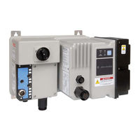
Rockwell Automation ArmorStart Bulletin 284G User Manual (324 pages)
Distributed Motor Controller
Brand:
Rockwell Automation
| Category:
Controller
| Size: 7 MB
Table of Contents
Table of Contents
5
Chapter 1 Introduction
11
Description
11
Introduction
11
Product Overview
11
Safety Armorstart
11
Mode of Operation
12
Bulletin 280G/281G - Full-Voltage Start
12
Bulletin 284G - Sensorless Vector Control
12
Operation
12
Description of Features
13
Overload Protection
13
LED Status Indication
15
Fault Diagnostics
15
Inputs
16
Gland Plate Entrance
16
Armorstart with Devicenet Network Capabilities
16
Devicelogix
16
Peer to Peer Communications (ZIP)
16
EMI Filter
16
Dynamic Brake Resistor
17
Control Brake Contactor
17
Inspecting
19
Installation and Wiring
19
Receiving
19
Storing
19
Chapter 2 Receiving
19
Unpacking
19
General Precautions
20
Precautions for Bulletin 280G/281G Applications
20
Precautions for Bulletin 284G Applications
21
Dimensions
22
Bulletin 280G/281G
22
Bulletin 284G
24
Bulletin 1000
26
Ground Wiring
31
Terminal Designations
32
Bulletin 280G Safety Product
33
Bulletin 281G Safety Product
34
Bulletin 284G Safety Product
35
Bulletin 1000 Safety Product
37
Safety Terminal Designations
44
Armorconnect Power Media
47
Description
47
Armorstart with Armorconnect Connectivity
49
Terminal Designations
50
Armorstart Safety with Armorconnect Connectivity
50
Armorconnect Cable Ratings
50
Branch Circuit Protection Requirements for Armorconnect Three-Phase Power Media
51
Group Motor Installations for USA and Canada Markets
51
Wiring and Workmanship Guidelines
51
Devicenet Network Installation
52
Other Devicenet System Design Considerations
52
Electromagnetic Compatibility (EMC)
53
General Notes (Bulletin 284G Only)
53
Grounding
53
Wiring
53
Introduction
55
Parameter Programming
55
Devicelogix™ Group
56
Parameter Group Listing
56
Devicenet Group
61
Starter Protection Group
64
Misc. Group
68
User I/O
68
ZIP Parameters
70
Starter Display
77
Starter Setup
78
Parameter Programming
81
Chapter 4 Bulletin 284G Programmable Parameters for Sensorless Vector Controllers
82
Parameter Group Listing
82
Devicelogix Group
83
Devicenet Group
88
Starter Protection Group
92
User I/O
95
Miscellaneous Group
96
Bits 3-15 Reserved
97
Drive Devicenet Group
98
Bulletin 284G Programmable Parameters for Sensorless Vector Controllers
98
Parameter Number
99
Minimum Value Maximum Value
99
Display Group
100
Default Value
102
Parameter Number
102
Access Rule GET
102
Minimum Value Maximum Value
102
Basic Program Group
105
Advanced Program Group
108
Bulletin 284G Programmable Parameters for Sensorless Vector Controllers/Related Parameters
117
Bulletin 284G Programmable Parameters for Sensorless Vector Controllers
118
Figure 4.1
118
Clear an Overvoltage, Undervoltage, or Heatsink Ovrtmp Fault Without Restarting the Drive
122
Related Parameters
123
Access Rule GET/SET
123
Maximum Value
123
Minimum Value Maximum Value
124
Default Value
125
How Step Logic Works
135
Step Logic Settings
135
Establishing a Devicenet Node Address
139
Node Commissioning Using Hardware
139
Node Commissioning Using Software
140
Building and Registering an EDS File
141
Using the Node Commissioning Tool Inside Rsnetworx for Devicenet
143
System Configuration
144
Default Input and Output (I/O) Assembly Formats (Bulletin 280G/281G)
145
Using Automap Feature with Default Input and Output (I/O) Assemblies (Bulletin 280G/281G)
145
Setting the Motor FLA and Overload Trip Class (Bulletin 280G/281G)
146
Default Input and Output (I/O) Assembly Formats (Bulletin 284G)
147
Using Automap Feature with Default Input and Output (I/O) Assemblies (Bulletin 284G)
147
Setting the Motor FLA (Bulletin 284G)
148
User Manual
149
Bill of Material
149
Accessories
149
Tools Menu
150
Node Comissioning
150
Explicit Messaging on Devicenet
151
Logic Controller Application Example with Explicit Messaging
151
Programming the 1747-SLC
152
I/O Mapping
152
Explicit Messaging with SLC
153
Setting up the Data File
154
Sequence of Events
155
Programming the 1756-Controllogix
158
I/O Mapping
158
Explicit Messaging with Controllogix
159
Setting up the MSG Instruction
159
Devicelogix Programming
163
Using Devicelogix
163
Devicelogix Programming Example
164
Armorstart Fault Bit, Status Bit, Outputs and Produced Network Bits in the Devicelogix Ladder Editor
167
Armorstart® ZIP Configuration
173
Overview
173
ZIP Parameter Overview
173
Data Consumption
175
Data Production
175
Mapping Consumed Data to the Devicelogix Data Table
175
Finding ZIP Bits in Device Logix Editor
184
Fault Display
185
Overview
185
Protection Programming
185
Clear Fault
186
Fault Codes
186
Fault Definitions
187
Short Circuit
187
Overload Trip
187
Phase Loss
187
Phase Short
187
Ground Fault
187
Stall
187
Control Power
187
I/O Fault
187
Over Temperature
187
Over Current
188
Devicenet™ Power Loss
188
Internal Communication Fault
188
DC Bus Fault
188
EEPROM Fault
188
Hardware Fault
188
Restart Retries
188
Miscellaneous Faults
188
Introduction
189
Troubleshooting
189
Bulletin 280G/281G Troubleshooting
190
Bulletin 284G Troubleshooting
193
Fault Definitions
193
Operation and Troubleshooting of the DB1- Dynamic Brake
195
Internal Drive Faults
198
Devicenet Troubleshooting Procedures
202
Control Module Replacement (Bulletin 280G/281G)
203
Control Module Replacement (Bulletin 284G)
204
Base Module Replacement (Bulletin 280G/281G)
206
Base Module Replacement (Bulletin 284G)
207
Appendix A Specifications
211
Bulletin 284G Specifications
216
Armorconnect™ Three-Phase Power Media
221
Power Tees & Reducer
222
Power Receptacles
223
Appendix B Electronic Data Sheets
225
Bulletin 280G/281G CIP Information
225
DOL Type Product Codes and Name Strings
225
Devicenet Objects
226
DOL Reversing Type Product Codes and Name String
226
Identity Object - CLASS CODE 0X0001
227
Identity Objects
227
Message Router - CLASS CODE 0X0002
227
Devicenet Object - CLASS CODE 0X0003
228
Assembly Object - CLASS CODE 0X0004
229
Custom Parameter Based "Word-Wise" I/O Assemblies
229
Word-Wise" Bit-Packed Assemblies
230
Standard Distributed Motor Controller I/O Assemblies
231
Standard Distributed Motor Controller Input Produced) Assemblies
232
Connection Object — CLASS CODE 0X0005
234
Discrete Input Point Object — CLASS CODE 0X0008
238
Discrete Output Point Object - CLASS CODE 0X0009
239
DOP Instances 1 and 2 Special Behavior
240
Parameter Object — CLASS CODE 0X000F
242
Parameter Group Object — CLASS CODE 0X0010
243
Discrete Input Group Object - CLASS CODE 0X001D
244
Discrete Output Group Object — CLASS CODE 0X001E
245
Control Supervisor Object -CLASS CODE 0X0029
246
Acknowledge Handler Object - CLASS CODE 0X002B
247
Overload Object - CLASS CODE 0X002C
248
Devicenet Interface Object -CLASS CODE 0X00B4
249
Appendix C Electronic Data Sheets
251
Bulletin 284G CIP Information
252
Devicenet Objects
252
Identity Object - CLASS CODE 0X0001
252
Identity Objects
253
Message Router - CLASS CODE 0X0002
253
Devicenet Object - CLASS CODE 0X0003
254
Assembly Object - CLASS CODE 0X0004
255
Custom Parameter Based
256
Word-Wise Bit-Packed Assemblies
256
Standard Distributed Motor Controller I/O Assemblies
258
Standard Distributed Motor Controller Output
258
(Consumed) Assemblies
259
Standard Distributed Motor Controller Input
259
(Produced) Assemblies
260
Inverter Type Distributed Motor Controller Input
260
Powerflex Native Assemblies
261
Connection Object - CLASS CODE 0X0005
263
Discrete Input Point Object - CLASS CODE 0X0008
268
Discrete Output Point Object - CLASS CODE 0X0009
269
Discrete Output Point Object Special Requirements
270
DOP Instances 3 and 4 Special Behavior
270
DOP Instances 1, 2, 9, and 10 Special Behavior
272
Parameter Object - CLASS CODE 0X000F
274
Parameter Group Object - CLASS CODE 0X0010
275
Discrete Input Group Object - CLASS CODE 0X001D
276
Discrete Output Group Object - CLASS CODE 0X001E
277
Control Supervisor Object -CLASS CODE 0X0029
278
Acknowledge Handler Object - CLASS CODE 0X002B
279
Devicenet Interface Object -CLASS CODE 0X00B4
280
Application of Armorstart® Controllers in Group Installation
281
Appendix D
291
IP67 Dynamic Brake Resistor
291
Appendix E
293
Armorstart Safety-Related Parts
293
Appendix F Armorblock Guard I/O Modules
294
Specifications
294
Armorblock Guard I/O Recommended Compatible Cables and Connectors
295
Maintenance and Internal Part Replacement
298
Safety-Related Specifications
298
Troubleshooting
299
Renewal Parts
301
Appendix G
309
Exclusive Control
309
Appendix H
310
Trim Control
310
PID Deadband
311
PID Reference and Feedback
311
PID Gains
312
PID Limits
312
PID Preload
312
Guidelines for Adjusting PID Gains
313
Step Logic Using Timed Steps
316
Appendix I
317
Step Logic Using Basic Logic Functions
317
Counter Function
318
Timer Function
318
Step Logic Parameters
319
Advertisement
Advertisement
Related Products
Rockwell Automation ArmorStart Bulletin 280G
Rockwell Automation ArmorStart Bulletin 281G
Rockwell Automation ARMORSTART 280D
Rockwell Automation ARMORSTART 281D
Rockwell Automation Allen-Bradley ArmorStart 283D
Rockwell Automation Allen-Bradley ArmorStart 284D
Rockwell Automation Allen-Bradley 2080-LC50
Rockwell Automation 2080-LC30-10QWB
Rockwell Automation 2080-LC70-24AWB
Rockwell Automation 2080-LC10-STARTERPACK
Rockwell Automation Categories
Controller
Control Unit
Power Supply
DC Drives
Industrial Equipment
More Rockwell Automation Manuals
Login
Sign In
OR
Sign in with Facebook
Sign in with Google
Upload manual
Upload from disk
Upload from URL