Eaton i-on Compact Quick Setup Manual
Hide thumbs
Also See for i-on Compact:
- Administration and user manual (50 pages) ,
- User manual (13 pages) ,
- Administration and user manual (63 pages)
Advertisement
Quick Links
Download this manual
See also:
User Manual
i-on Compact
Quick Setup Guide
Introduction
This guide provides a quick overview of
how to set up standard features of an i-on
Compact control unit.
Note: Details of all features and options are
available in the i-on Compact Engineering
Guide , and i-on Compact Admin & User
Manual , which you can download from
www.touchpoint-online.com.
Step 1: Power-up the control unit
After installing all hardware (as described in the Installation
Guide ):
1. Switch on the mains supply to the control unit.
2. Follow the on-screen prompts. When you see the following,
enter a four-digit installer access code of your choice, then
enter it again when prompted. DO NOT FORGET THIS CODE!
NEW INSTALLER CODE
(
3. When you see the following, enter a four-digit access code
of your choice for User 1 (master user) , then enter it again
when prompted. DO NOT FORGET THIS CODE!
NEW USER 1 CODE
(
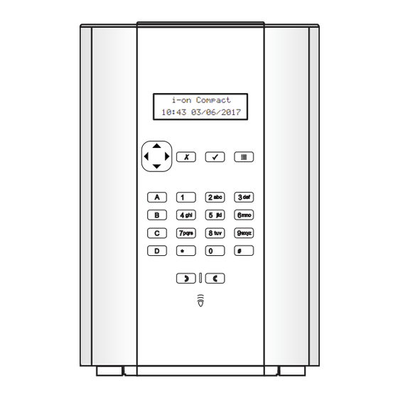
4. The standby screen is displayed. For example:
i-on Compact
12:00 01/12/2017
)
)
i-on Compact
10:43 03/06/2017
Advertisement

Related Manuals for Eaton i-on Compact


Summary of Contents for Eaton i-on Compact
- Page 1 Compact control unit. Note: Details of all features and options are available in the i-on Compact Engineering Guide , and i-on Compact Admin & User Manual , which you can download from www.touchpoint-online.com. Step 1: Power-up the control unit...
-
Page 2: Installer Menu
Step 2: Enter installer mode 2. Close the cover. 3. From the top level of the Installer Installer mode gives you access to menu: the installer options. To enter installer a. Select Detectors/Devices . mode: b. Select Detectors . 1. Make sure the standby screen is c. - Page 3 # to change between capital 3. Insert the batteries into the siren. • and lower-case letters. 4. The display shows “Siren u or n to move the cursor assigned to Siren xx” and the • left or right. signal strength (0-9). 5.
- Page 4 Step 5c: Choose the zone Final Door Set — The system • sets after closing a door fitted attributes with a Final Exit zone detector. Once the door closes, the Attributes define how a detector will system sets after the Settle react under certain conditions.
- Page 5 Step 9: Configure e. Assign the remote (press any button). SecureConnect™ f. Assign a radio Hold Up Alarm (HUA) Press both orange SecureConnect allows users to set buttons. Press if there is no or unset the alarm system, switch HUA.
- Page 6 Installer menu map The following menu map shows all options in the Installer menu and their locations. Please refer to the Engineering Guide for details of these options. 1 Detectors/Devices Detectors Add/Del Detectors Zone nnn... Delete all Program Zones Zone 000... Name Type Attributes...
-
Page 7: Setting Options
Cameras IP Cam 1... Camera Triggers Zone Follow Zone Alarm IP Address HTTP Port Internal 2 Outputs Radio outputs Add Outputs Edit Outputs EDIT RADIO O/P 1... Name Type Pulsed Zones Delay On Time 3 Setting options Name Full Set Exit Mode Settle Time Exit Time... -
Page 8: System Options
4 System Options User Options User Access HUA keys active Quick set Quick omit User code reqd 2 Way Replies 2W Set Instant Tamper Omit Silence Alerts User Reset Zone alarms Zone tampers System tampers CSID Code Restore Defaults Staged defaults User Zones Radio Devices... - Page 9 Hardware On-board Sounder Volume A/C Fail Reporting Mains Fail Delay Ext DC Fail Reporting Ext DC Fail Delay GSM Antenna Radio Options Supervision Jamming Remotes Remote needs Entry Remote Entry PrtSt Force Set i-rk01 RKP needs Entry RKP Entry PrtSt Perimeter Options PZ Unset Response (displayed only if there is a...
- Page 10 Burg Comms Rearm 21CN FF Ack time Send Tamp As Burg Dynamic Test Call Static Test Call Unset Comms Outgoing Call Mode Messages Triggers Destinations PSTN SMS Incoming Remote Control Forwarding Email Call Mode Messages Home Message Message 1-4 Triggers Message 1-4 Destinations Message 1-4...
- Page 11 Hostname Username Password Last Update Status Detected ext. IP 6 Test Sirens & Sounders Ext. Radio Sirens On-board Sounder Internal Sounders On-board Keypad Radio Keypads Walk Test Chime System Zones Signal Strengths Detectors Radio Keypads External Sirens WAMs Internal Sounders Outputs Radio Outputs Remotes...
- Page 12 OF THIS DOCUMENT SHALL NOT BECOME PART OF OR MODIFY ANY CONTRACT BETWEEN THE PARTIES. In no event will Eaton be responsible to the purchaser or user in contract, in tort (including negligence), strict liability or other-wise for any special, indirect, incidental...
Need help?
Do you have a question about the i-on Compact and is the answer not in the manual?
Questions and answers