Table of Contents
Advertisement
Quick Links
Advertisement
Table of Contents

Related Manuals for Elster 6 Series


Summary of Contents for Elster 6 Series
- Page 1 73023467_B_EN i 2018-06-07 Doc: 10000050188...
- Page 2 Elster GmbH Steinern Strasse 19-21 D - 55252 Mainz-Kastel, Germany Tel.: +49 6134 6050 Fax: +49 6134 605 566 E-Mail: info@elster-instromet.com Page 2 of 68 Operation and Maintenance UFM Series 6 Q.Sonic-plus...
-
Page 3: Table Of Contents
Contents General Information About these Instructions Limitation of Liability Text Labelling Presentation of Safety and Risk Instructions 2.1.1 Paragraph Formats 2.1.2 Character Formats 2.1.3 Abbreviations Ultrasonic Flow Meter Series 6 General Applicable Standards Configuration Calibration Theory of Operation Flow Velocity Measurement Correction after Calibration Volume Flow at Line Conditions System Description... - Page 4 Contents 5.6.3 FM Certified 5.6.4 CSA Certified Sealing 5.7.1 Main Plate 5.7.2 SPU Installation and Commissioning Introduction Flow Cell Installation Requirements 6.2.1 Installing a Meter in the Pipeline 6.2.2 Testing Installation Wiring Instructions SPU Configuration Cold Commissioning Hot Commissioning Operation LED at Display Front Panel and Touch Display Basic Display...
- Page 5 Contents 8.2.5 Presentation of AGC-Levels and AGC-Limits 8.2.6 Swirl Angle Exchanging Components 8.3.1 Pressure Sensors Exchange 8.3.2 Temperature Sensors Exchange 8.3.3 Transducer Exchange 8.3.4 SPU Exchange Verifying Software Versions Verifying the Components with their Checksums Verifying the Software Status of the Parameter Build Up Display Test Checking Errors and Warnings PC Software Package...
-
Page 6: General Information
If you have any questions, or need further details on specific matters concerning this product, please do not hesitate to contact one of our staff info@elster-instromet.com members by email at (or see more contact information on page 2). -
Page 7: Limitation Of Liability
General Information 1.2 Limitation of Liability This manual is based on the latest information available. It is provided subject to alterations. We reserve the right to change the construction and/or configuration of our products at any time without obligation to update previously shipped equipment. -
Page 8: Text Labelling
Current warranty conditions in the General Terms and Conditions are available on our website: http://www.elster-instromet.com/en/general-terms-of-business 2 Text Labelling This manual employs consistent visual cues and standard text formats to help you easily locate and interpret information. This information will help you quickly identify relevant content. -
Page 9: Paragraph Formats
Text Labelling Tips and Recommendations Tips include notes and information that make it easier for the user. Tips are described below: Heading (optional) Hint text 2.1.1 Paragraph Formats This triangle prompts you for an action. ► This character will show you the immediate result of your action. Example Multi-row examples are marked by two continuous blue lines and the keyword “Example”. -
Page 10: Character Formats
Text Labelling 2.1.2 Character Formats Example See Chapter 5 System References to additional information are Description (p.18) marked with an arrow. If the arrow refers to information within the document, these references are formatted as hyperlinks in blue font. You can go directly to the corresponding section by clicking on the blue text. -
Page 11: Abbreviations
Text Labelling 2.1.3 Abbreviations The following abbreviations may appear in this document: Application Function Block ATEX Atmosphères Explosibles; European Directive 94/9/EC on equipment and protective systems intended for use in potentially explosive atmospheres New Directive (valid 20.04.2016): 2014/34/EU Canadian Standards Association Direct Current European Community ElectroMagnetic Compatibility;... -
Page 12: General
• SPU type plate: Provides information on applicable hazardous area approval. Ensure the meter never operates outside the limits stated on the type plates. Any discrepancy between the type plates should be reported to Elster or your local agent immediately. Please refer to Chapter 5.6 Labels and Nameplates (p.22) for more information. -
Page 13: Applicable Standards
Ultrasonic Flow Meter Series 6 3.2 Applicable Standards The Ultrasonic Flow Meter Series 6 is manufactured to be in accordance with European Directives: ATEX, PED, EMC and optionally MID. If the meter is ordered for use at a location where European Directives are NOT mandatory, the meter can alternatively be manufactured in compliance with IECEx, FM Approval or CSA certificate for use in hazardous areas. -
Page 14: Calibration
Ultrasonic Flow Meter Series 6 Q.Sonic plus Path Configuration Top view: Front view: Trd. Path Nr: Path Type: 1A / 1B Swirl path (B1-CW*) 2A / 2B Swirl path (B1-CCW**) 3A / 3B Axial path (A1) 4A / 4B Axial path (A2) 5A / 5B Swirl path (B2-CW*) 6A / 6B... -
Page 15: Theory Of Operation
Theory of Operation If the Q.Sonic plus meter has to be in accordance with MID, extra restrictions should be taken into account. Please see Chapter 12.4 Calibration (p.64). 4 Theory of Operation An ultrasonic flow meter is an inferential measurement device that consists of ultrasonic transducers that are typically located along a pipe's wall. -
Page 16: Correction After Calibration
Theory of Operation be shorter, while the upstream ones “t “ will be longer as compared when the gas is not moving. The equation below illustrates the computation: ... -
Page 17: Volume Flow At Line Conditions
Theory of Operation 4.3 Volume Flow at Line Conditions The volume flow at line conditions Q is the (adjusted) profile-corrected Line gas velocity V multiplied by the internal cross section A of the flow cell: line line line ... -
Page 18: System Description
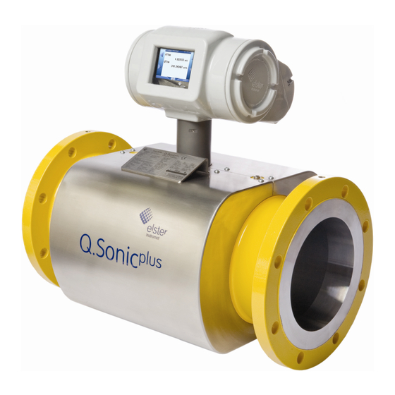
SPU label (rear side) Main Type Temperature Plate Sensor (rear side) Pressure Ultrasonic Connection Transducer Pressure Flow Cell Sensor (optional) Figure 5-1: Example of an Elster Ultrasonic Gas Flow Meter Page 18 of 68 Operation and Maintenance UFM Series 6 Q.Sonic-plus... -
Page 19: Signal Processing Unit
System Description 5.2 Signal Processing Unit The SPU is mounted in an explosion proof housing. The box consists of two separate compartments; a main and a rear compartment (see Figure 5-2). The main compartment can be opened from the side of the SPU and contains the main circuit boards. -
Page 20: Transducers
System Description 5.3 Transducers The ultrasonic signals required for the flow measurement are generated and received by ultrasonic transducers. Piezoelectric transducers employ crystals or ceramics that are set into vibration when an alternating voltage is applied to the piezoelectric element. The vibrating element generates sound waves in the gas. -
Page 21: Flow Cell Pressure Sensor (Optional)
System Description 5.4 Flow Cell Pressure Sensor (Optional) As an optional feature the UFM can be equipped with a pressure sensor. This pressure sensor is used for: Reynolds flow profile correction Compensation of the flow cell expansion due to gas pressure. CAUTION! The pressure sensor is not used for volume conversion. -
Page 22: Labels And Nameplates
System Description 5.6 Labels and Nameplates Nameplates and labels are used to identify the product and to provide details on the specific product. Together with the product manual it specifies how the product is certified and designed. The main (type) plate (see Figure 5-5, for an example of a plus Q.Sonic main plate) provides information on mechanical design... -
Page 23: Atex Certified
System Description 5.6.1 ATEX Certified The explosion proof housing has the following ATEX certification information: Classification: Ex II 2 G Ex d ia [ia] IIB+H2 T6 Gb IP66 -50 °C ≤ Tamb ≤ +60 °C ATEX markings: II 2 G 0044 0044 is the notified body number of TÜV NORD CERT GmbH ... -
Page 24: Fm Certified
System Description Warning: Read instruction manual before operating device Figure 5-7: Example of an IECEx Label 5.6.3 FM Certified The explosion proof housing has the following FM certification information: Explosion proof for Class I, Division 1, Group A, B, C and D ... -
Page 25: Csa Certified
System Description 5.6.4 CSA Certified The explosion proof housing has the following CSA certification information: Explosion proof for Class I, Division 1, Group B, C and D T6 Ex d ia [ia] IIB + H2 T6 -50 °C < Tamb < +60 °C ... -
Page 26: Sealing
System Description 5.7 Sealing This chapter describes the important sealing locations and sealing process as required by MID certificate T10335 ( see also Chapter 12 MID Requirements [p.63]). Even if MID is not required it is advised to seal the UFM. - Page 27 System Description Figure 5-11: Example of a PCB sealing bracket The meter should be protected from undesired changes in the software. Therefore a hardware switch is placed on the main board. This hardware switch can be reached through an opening in the back panel.
- Page 28 System Description Sealing switch on the mainboard is accessible after removing the protective cap. Meter unsealed: both pins down (Towards the print board) Meter sealed: both pins up (Away from the print board) Backpanel with Protective Cap (Screw sockets are used for sealing) Figure 5-12: Hardware protection on the main board In addition to the hardware protection, access to the meter software is secured by different user access levels and...
-
Page 29: Installation And Commissioning
Appendix I – References for a complete list of related documentation. Also look at your project data to see if extra documentation is required and delivered. If documentation is missing, contact Elster or your local agent immediately. 6.2 Flow Cell Installation Requirements 6.2.1... -
Page 30: Testing Installation
Installation and Commissioning WARNING! To avoid possible injury, make sure the lifting equipment is suitable for the weight of the Ultrasonic Flow Meter Series 6. Always use the lifting lugs and make sure lifting equipment is certified and shows no damage or wear. Eyebolts must be inspected before each use and used according to the manufacturer’s specification. -
Page 31: Wiring Instructions
(SonicExplorer). Diagnostics and status per measuring path and the zero flow can be checked, assuming there is sufficient pressure in the meter. A technician of Elster will, if this has been agreed, verify measurements and check the system performance. -
Page 32: Hot Commissioning
Installation and Commissioning 6.6 Hot Commissioning The hot commissioning is in most cases the last test of the UFM and can be witnessed by a representative of the client and, if required, by an inspector of weights and measures for the official sealing. Under this condition there is process gas in the pipe and a flow test is being performed. -
Page 33: Operation
Operation 7 Operation This chapter describes how the UFM Series 6 can be operated through the interactive touch screen display on the meter. 7.1 LED at Display 2 LEDs provide an overall status indication of the meter. LED 1 LED 2 Figure 7-1: LED at Display Power LED - LED 1 at Figure LED Status... - Page 34 Operation Status LED - LED 2 at Figure LED Status Description Power is off or; the device is running warning and error free. Yellow, A warning is pending that does not affect the metrology flashing relevant functionalities. * Yellow, At least one warning that does not affect the metrology permanently relevant functionalities was pending but has already illuminated...
-
Page 35: Front Panel And Touch Display
Operation 7.2 Front Panel and Touch Display The SPU contains an interactive touch screen display, showing the most important measurements and diagnostics (line flow, gas velocity, speed of sound, totalizers …). It contains a touch screen with 7 touch areas (see Figure 7-2) These touch areas will disappear when not in use and reappear with a touch of the screen in one of the 7 touch areas. -
Page 36: Basic Display
Operation 7.3 Basic Display The basic display is shown below in Figure and displays the following values: Qline - Gas line flow running through the meter in m Vm FWD (Volume Forward) - Total amount of gas volume passed through the meter in the positive direction. -
Page 37: Home Screen
Operation 7.4 Home Screen Pressing the Home button from the Basic Display (as seen in Figure 7-3) will bring you to a screen as depicted below in Figure 7-4. Figure 7-4: Home Screen and Menu Touch the screen in one of the 7 touch areas to activate the arrows. Use the arrow buttons on the left and right to navigate and highlight a particular option on the screen. - Page 38 Operation Info (Basic Information) In this menu some general important information about the meter can be found, regarding: Device Monitor information, Software status, License information, and the IP address. Through this menu it is also possible to perform a display test. Please see Figure 7-5. After selecting Display test, the screen will alternate between black and white.
- Page 39 Operation up and select your desired filter, as seen in Figure 7-6. A logbook of errors is available on the right hand side. Figure 7-6: Error List and Filter System The System screen contains general system information including Time Service (setting the date and time), Users (logging in with appropriate user rights), an Error List, an Audit trail, Intelligent measurement devices, and Measurement tools.
- Page 40 Operation Time Service – To program the date and time of the meter: Highlight Date & Time (from Basic Display -> Time Service) ► Press the select arrow ► Highlight and select Update date and time when you have entered the ►...
- Page 41 Operation user manual, available at http://www.docuthek.com/. By choosing the right Group and Channel and selecting Show values it is possible to see all important data of the selected archive (see Figure 7-9). Figure 7-9: Archives Screen Modbus This menu will bring you to the Modbus protocol screen. Modbus Registers are listed on the left hand side, with corresponding values on the right.
-
Page 42: Diagnostics
OK: Everything is working properly (Operational Reduced Acc.: There are some paths which are failing, Status) nevertheless the measurement is still suitable for custody transfer. Contact Elster or your local representative. Page 42 of 68 Operation and Maintenance UFM Series 6 Q.Sonic-plus... - Page 43 Non fiscal: There are some paths which are failing; measurement is no longer suitable for custody transfer. Contact Elster or your local representative. No Measurement: all paths are failing. Contact Elster or your local representative. VoS_avg Average measured Velocity of Sound of the gas.
- Page 44 Operation As seen in Figure 7-12, on the diagnostics page you may also choose from two sub-menus: Per Path Per Diagnostic These sub-menus are shown on the top of the display, and will disappear if you scroll down. Use the “up” arrow to make them reappear.
- Page 45 Operation Figure 7-13: Diagnostic view: Per Path Per Diagnostic Per Diagnostic is broken down into 5 subsections: VoG Raw (Velocity of Gas Raw) VoS Raw (Velocity of Sound Raw) Profile Diagnostics, Performance Correction Factors UFM Series 6 Operation and Maintenance Page 45 of 68 Q.Sonic-plus...
- Page 46 Operation A description of each diagnostic follows: VoG Raw and VoS Raw These subsections display the raw Velocity of Gas and Velocity of Sound results. b) Profile Diagnostics Profile Diagnostics displays an array of useful calculations including: Profile Factor Axial/Swirl, Swirl Angle, Axial Asymmetry, Horizontal Asymmetry, Reynolds PathType A and Reynolds PathType B.
- Page 47 Operation Figure 7-15: Performance display Correction Factors This section provides an overview of all correction factors of the meter. k – factor Geometry Corr. – This correction factor corrects the size of the flow cell’s body, based upon the measurements of the internal pressure and temperature sensors.
-
Page 48: Info
Operation This is useful if the process conditions differ significantly from the conditions during the calibration process since both high pressure and high temperature results in an increase in the tube cross-section and a change in path lengths and angles. Please Note: k-factor GeomCorr. - Page 49 Outcome can be OK or FAIL. If a FAIL is encountered, the selftest should be done again. If it continues to fail, contact Elster or your local agent. SW versions (internal) – Herewith all software versions and their matching checksum in the electronics can be read.
-
Page 50: Maintenance
As a result the transducers and the electronics are virtually maintenance free. However, Elster recommends inspection of the UFM at regular intervals, for example weekly or monthly evaluations. In case of deterioration of the meter, appropriate measures should be taken before a serious failure occurs. -
Page 51: Performance
Maintenance The sample rate is programmable to be anything between 1 and 100Hz. However, the actual sample rate may be lower than the programmed value since, particularly with large size meters, the travel times of the ultrasonic pulses in the gas do not allow for the programmed sample rate. The UFM will then adjust the sample rate to the highest possible value. -
Page 52: Presentation Of Agc-Levels And Agc-Limits
The meter operates reliably if the angle is between -20° and +20°. If the indicated swirl angle exceeds these values please consult Elster for support. Page 52 of 68 Operation and Maintenance UFM Series 6 Q.Sonic-plus... -
Page 53: Exchanging Components
Spare parts of the Ultrasonic Flow Meter Series 6 metering system must be supplied by Elster. After exchanging parts of the Q.Sonic Series 6 metering system the present “calibration” sealing must be renewed. Please see Chapter 5.7 Sealing... -
Page 54: Temperature Sensors Exchange
[p.21]). As the temperature sensors are specially designed for the Ultrasonic Flow Meter Series 6, they may only be exchanged with sensors from Elster. As the temperature sensor only measures the flow cell temperature and is not in contact with the gas in the pipe, exchanging can be done under pressure. -
Page 55: Spu Exchange
An SPU exchange will not affect the measuring characteristics and accuracy (and as a consequence the calibration) of the UFM. However if the board is sealed after calibration, please contact Elster or your local representative before proceeding with the exchange. - Page 56 Maintenance Ultrasonic Flow Meter Series 6 Exchanging Boards at the Rear Compartment of the SPU Both documents are listed in Appendix I – References. Page 56 of 68 Operation and Maintenance UFM Series 6 Q.Sonic-plus...
-
Page 57: Verifying Software Versions
Verifying Software Versions 9 Verifying Software Versions It’s possible to verify the software version with checksum for all components. This should be done with two different methods. Figure and Figure show the steps to complete this process. 9.1 Verifying the Components with their Checksums Start from the Front Panel (main display) ►... -
Page 58: Verifying The Software Status Of The Parameter Build Up
Verifying Software Versions 9.2 Verifying the Software Status of the Parameter Build Up If you are at the front panel, go to the Home page ► Select Info ► Go to Software Status ► A list is presented with the status of the software modules. Figure 9-2: Checking software versions and checksum through the front panel Page 58 of 68 Operation and Maintenance... -
Page 59: Display Test
Verifying Software Versions 9.3 Display Test Display test of the screen can be carried out as follows: If you are at the front panel, go to the Home page ► Choose Info ► Go to Display Test ► The display will alternate between black and white. Press any button to stop the test. -
Page 60: Pc Software Package
Figure 9-4: Errors/Warnings List 9.5 PC Software Package For configuration and monitoring of the Ultrasonic Flow Meter Series 6 Elster has developed a software package called SonicExplorer. This program is specially designed to perform advanced monitoring of the Ultrasonic Flow Meter Series 6. -
Page 61: User Rights / Login
– read access only User1 and User2 do not have a default password set. Just leave “Password” blank and click “OK”. To request an administrator password please contact Elster at: Aftersales.Essen@elster.com UFM Series 6 Operation and Maintenance Page 61 of 68 Q.Sonic-plus... -
Page 62: Shipping And Storage
Shipping and Storage 11 Shipping and Storage As the Ultrasonic Flow Meter Series 6 is a delicate instrument, care should be taken to carefully handle and store the flow meter in a proper way. Improper handling, shipping, or storing may void its warranty. The Ultrasonic Flow Meter Series 6 should be stored in indoor conditions, with a low humidity (5% - 95% non-condensing);... -
Page 63: Mid Requirements
The Ultrasonic Flowmeter Series 6 Q.Sonic is compliant with Environment Class M1 / E2 New European Directive valid from 20.04.2016: 2014/32/EU 12.2 EC Declaration of Conformity Elster ultrasonic gas flow meters are manufactured in accordance with applicable directives, e.g.: Pressure Equipment Directive (PED) ... -
Page 64: Sealing
MID Requirements 12.3 Sealing An MID compliant meter shall be sealed. See Chapter 5.7 Sealing (p.26) for more information. 12.4 Calibration An MID compliant meter is accompanied by a copy of the EC Declaration of Conformity stating compliance with Measuring Instruments Directive 2004/22/EC Annex MI-002, based on: ... -
Page 65: Index
Index 13 Index Abbreviations, 11 Filter, 37 Archive, 39 Flow Cell, 18 ATEX Certified, 23 Flow Conversion AFB, 66 Flow Velocity Measurement, 16 FM Certified, 24 Front Panel, 34 Basic Display, 35 Gas Quality AFB, 74 Calibration, 14 Gas Velocity (Zero Flow Character Formats, 10 Measurement), 50 Checksums, 55... - Page 66 Index Login, 58 Sample Rate, 49 Selftests, 48 Signal Processing Unit, 19 Main Plate, 26 Software status, 37 Measurement tools, 38 SonicExplorer., 58 MID Requirements, 60 SPU, 26 Modbus, 40 SPU Configuration, 30 SPU Exchange, 54 Standards, 13 Swirl Angle, 51 Nameplates, 22 System, 38 Open Grid European Dorsten, 15...
-
Page 67: Appendix I - References
Appendix I – References Appendix I – References All references below can be obtained from Elster. Additionally, most references are available online at: http://www.docuthek.com. MID Certificate T10335 (last valid version) Doc. No.: T10335_certificate plus UFM Series 6 Q.Sonic Operation and Maintenance Manual SAP Ref.:... - Page 68 Appendix I – References UFM Series 6 Modbus Protocol SAP Ref.: 73023466 Doc. No.: 10000050187 (last valid revision) UFM Series 6 Transducer Exchange at Atmospheric Conditions SAP Ref.: 73023472 Doc. No.: 03.200.001.001/02/2 (last valid revision) [10] Retraction Tool NG Transducers SAP Ref.: 73023473 Doc.
Need help?
Do you have a question about the 6 Series and is the answer not in the manual?
Questions and answers