Sign In
Upload
Manuals
Brands
Datex-Ohmeda Manuals
Medical Equipment
Aestiva 7900 SmartVent
Datex-Ohmeda Aestiva 7900 SmartVent Manuals
Manuals and User Guides for Datex-Ohmeda Aestiva 7900 SmartVent. We have
2
Datex-Ohmeda Aestiva 7900 SmartVent manuals available for free PDF download: Technical Reference Manual, Service Manual
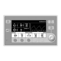
Datex-Ohmeda Aestiva 7900 SmartVent Technical Reference Manual (204 pages)
Anesthesia Ventilator
Brand:
Datex-Ohmeda
| Category:
Medical Equipment
| Size: 2.85 MB
Table of Contents
Table of Contents
5
Important
4
Technical Competence
4
Table of Contents
5
1 Introduction
11
What this Manual Includes
12
Software Versions
12
Standard Service Procedures
13
Operation Manuals
13
Service Manuals
13
Ventilator Tests
13
Symbols Used in the Manual or on the Equipment
14
2 Theory of Operation
17
Aestiva 7900 Ventilator Features
18
Safety Features
19
General Description
18
Aestiva 7900 Ventilator Components
19
Ventilator Control Electronics
20
Control Panel and Display
22
Sensor Interface Board (SIB)
23
Pneumatic Engine
23
Electrical
24
Electrical (Original)
24
Electrical (Integrated)
25
Power Supply (Original)
26
Power Supply (Integrated CPU)
27
Sealed Lead Acid Battery
28
CPU Assembly
29
Sensor Interface Board (SIB)
36
Mechanical Subsystems
39
Supply Gas
39
Gas Inlet Valve (GIV)
40
Flow Control Valve
40
Drive Gas Check Valve (DGCV)
41
Bellows Pressure Relief Valve
41
Exhalation Valve
42
Mechanical Overpressure Valve
42
Bleed Resistor
42
Free Breathing Valve
43
Breathing Circuit Flow Sensors
43
3 Post-Service Checkout
45
Test the Aestiva 7900 Ventilator
46
Test the Aestiva Anesthesia Machine
46
4A Tests and Calibration - Software Revision 4.X
47
4 Tests and Calibration - Software Revision
47
4A.1 Self Tests
49
4A.2 Service Mode Confirmation Menu
50
4A.3 Main Menu - Service Mode
51
4A.3.1 Alarm Log
52
4A.3.2 Error Log
53
4A.3.3 System Configuration
54
4A.3.4 User Select Defaults
58
4A.3.5 Test CPU and Memory
60
4A.3.6 Test EEPROM
61
4A.3.7 Test GIV
62
4A.3.8 Test Flow Valve
63
4A.3.9 Test Drive Pressure Limit Switch
64
4A.3.10 Test 5V Fail Alarm
65
4A.3.11 Test Serial Ports
66
4A.3.12 Breathing System Leak Test
67
4A.3.13 Display A/D Channels
68
4A.3.14 Display Discrete I/O Signals
70
4A.3.15 Display Battery Status
71
4A.3.16 Test Panel Switches
72
4A.3.17 Flow Valve Test Tool
73
4A.3.18 Adjust Drive Gas Regulator
74
4A.3.19 O2 Calibrations
75
4A.3.20 Calibrate Flow Sensors
76
4A.3.21 Pressure Sensitivity
77
4A.3.22 Calibrate Flow Valve
78
4A.3.23 Bleed Resistor Calibration
79
4A.3.24 Service Calibrations Required
80
4B Tests and Calibration - Software Revisions 1.X and 3.X
83
4B.1 Self Tests
85
4B.2 Service Mode Confirmation Menu
86
4B.2.1 Set the Altitude
87
4B.2.2 Set the Language
87
4B.2.3 Set the Serial Connection
87
4B.3 Main Menu - Service Calibration Mode
88
4B.4 Diagnostic Tests
89
4B.4.1 Test CPU
89
4B.4.2 Test External RAM
89
4B.4.3 Test Display RAM
90
4B.4.4 Test Flash ROM
90
4B.4.5 Test EEPROM
91
4B.4.7 Test Serial Ports
92
4B.4.8 Test Flow Valve
93
4B.4.9 Test GIV (Gas Inlet Valve)
94
4B.4.10 Test DPL (Drive Pressure Limit) Switch
95
4B.4.11 Test 5V Fail Alarm
96
4B.5 Diagnostic Tools
97
4B.5.1 Display A/D Channels
97
4B.5.2 Display I/O Signals
99
4B.5.3 Battery Charge Status
100
4B.5.4 System Error Log
101
4B.5.5 Alarm Log
101
4B.6 Flow Valve Test Tool
102
4B.7 Test Breathing System for Leak
103
4B.8 Adjust Drive Gas Regulator
104
4B.9 Calibrations
105
4B.9.1 Calibrate O2 Sensor
105
4B.9.2 Calibrate Flow Sensors
106
4B.9.3 Pressure Sensitivity Calibration
107
4B.9.4 Calibrate Flow Valve
108
4B.9.5 Calibrate Bleed Resistor
109
4B.10 Schedule Service Calibration - Software 3
110
4B.11 Sensor(S) Cal Due - Software 1
111
4B.12 User Settings
112
4B.12.1 Select Altitude
112
4B.12.2 Select Drive Gas
112
4B.12.3 Adjust Brightness
113
4B.12.4 Select Heliox Mode
113
4B.12.5 VE Alarm Limits
114
4B.12.6 User Select Defaults
114
5 Troubleshooting
117
5 Troubleshooting
118
Troubleshooting Instructions
118
System Error Log
119
Error Messages for Software Revision 4.X
119
Error Codes for Software Revisions 1.X and 3.X
119
Alarm Messages
123
Mechanical/Electrical Troubleshooting Guide
140
Troubleshooting Flowcharts
142
Ventilator Assessment Process
142
No Display Troubleshooting
143
Inaccurate Volume Ventilation Troubleshooting
144
No Ventilation Troubleshooting
145
High Intrinsic PEEP Troubleshooting
146
Power Supply Test Points
147
Power Supply Board (Original CPU)
147
Original CPU
148
Power Supply (Integrated CPU)
149
6 Maintenance
151
Supply Gas Inlet Filter
153
Free Breathing Valve Maintenance
154
MOPV Differential Relief Valve Test
155
MOPV Pressure Relief Valve Test
156
7 Repair Procedures
159
Control Panel Assembly
160
Keyboard and el Display
161
Encoder Switch
162
Alarm Speaker
163
Access to Electrical Enclosure Components
164
CPU Board
165
CPU Board
166
Firmware Replacement Procedure
167
Power Supply Board (for Original CPU)
168
Power Supply (for Integrated CPU)
169
Toroid (Original CPU Only)
170
Battery
171
Vent Engine
172
Non-Relieving Regulator
174
Flow Control Valve
175
Gas Inlet Valve
176
Mechanical Overpressure Valve (MOPV Assembly)
178
To Service the Original MOPV Assembly
178
To Service the MOPV Assembly with the Molded Housing
180
Drive Gas Check Valve Assembly
181
8 Illustrated Parts
183
Service Tools
184
Special Instructions
184
Ventilator Harnesses
185
Electrical Enclosure Parts (Original CPU)
186
Electrical Enclosure Parts (Integrated CPU)
188
Display Module
190
Rear Housing Parts
190
Front Housing Parts
191
Aestiva 7900 Vent Engine
192
Gas Inlet Valve
193
Inlet Filter
195
Free Breathing Valve
196
Manifold
197
Tube Assembly
198
Twin Tube Lifter
199
Vent Engine Mounting Bracket
200
Sensor Interface Board (SIB)
201
Advertisement
Datex-Ohmeda Aestiva 7900 SmartVent Service Manual (181 pages)
Brand:
Datex-Ohmeda
| Category:
Fan
| Size: 1.96 MB
Table of Contents
Table of Contents
5
List of Illustrations
11
1/ Introduction
14
What this Manual Includes
14
Symbols
15
7900 Ventilator Configuration
17
Operation and Service Manuals
17
Software Versions
17
Standard Service Procedures
17
Ventilator Tests
17
2/Theory of Operation
19
General
19
7900 Ventilator Features
20
Mechanical
21
Safety Features
21
Electrical
27
Power Supply
28
Power Supply Assembly
28
Synchrononus Step-Down Regulator
30
Communication Interface (RS232C)
32
External Interface
32
External Interface Connector
32
Input
32
Output
32
Sealed Lead Acid Battery
32
Functional Specifications
33
Microcontroller Assembly
33
Flash EPROM
35
Non-Volatile Memory
35
Program Memory
35
Safety Relevant Computing
35
System RAM
35
68040 Software Watchdog Timer
36
Error Response Sequence
36
Operating Mode Watchdog
36
Watchdog Systems
36
Analog to Digital Converter System
37
DATA Acquisition
37
A/D Converter
38
Multiplexer and Buffer Amplifier
38
Flow Valve Control
39
Voltage Reference
39
EL Display Controller
40
Front Panel Display Interface
40
Gas Inlet Valve Drive Circuit
40
LED Driver Outputs
40
Membrane Switch Inputs
40
Rotary Encoder Input
40
Video Display Memory
40
Audio Alarm
41
Front Panel Assembly
41
Manifold Pressures
41
Mechanical Ventilation Switch
41
Inspiratory and Expiratory Flow Measurement
42
Patient Airway Pressure Measurement
42
Sensor Interface Board (SIB)
42
O2 Concentration Measurement
43
Switch Connections
43
3/Post Service Checkout
45
Test All Options and Accessories
45
Test the Anesthesia System
45
Test the Ventilator
45
4/Tests and Troubleshooting
47
Overview
47
Testing Requirements
47
Service Mode Menu
49
Diagnostic Tests
50
Test CPU
50
Test Display RAM
51
Test External RAM
51
Test Flash ROM
52
Test EEPROM
53
Test Panel Switches
54
Test Serial Ports
56
Test Flow Valve
57
Gas Inlet Valve FAIL Instructions
58
Test Gas Inlet Valve (GIV)
58
Test Pressure Limit Switch
59
Pressure Limit Switch FAIL Instructions
60
Diagnostic Tools
61
Display A/D Channels
61
Display I/O Signals
62
Display Battery Charge Status
63
System Error Log
64
System Error Log Codes
65
Verify Flow
69
Calibrations
70
Calibrate Flow Sensors
71
Calibrate Pressure Sensitivity
74
Calibrate Flow Valve
76
Calibrate Bleed Resistor
77
Sensor(S) Cal Due
80
Select Altitude
81
Select Drive Gas
81
User Settings
81
Adjust Brightness
82
Select Heliox Mode
82
Exit Service Mode
83
Troubleshooting Guides
84
Troubleshooting Mechanical/Electrical
84
Troubleshooting by Alarm Messages
86
Maintenance
91
Maintenance Schedule
91
Two Year Maintenance
91
Yearly Maintenance Checks
91
Exhalation Valve Maintenance
92
Maintenance Procedures
92
Supply Gas Inlet Filter
92
Free Breathing Valve Maintenance
93
6/ Repair Procdures
95
Assemblies -- Tools for Removal and Installation
95
General
95
Removing the 7900 Ventilator from the Integrated Machine
96
Removing the 7900 Ventilator from the Ohmeda Excel/Modulus SE Gas Machine
96
Removing the 7900 Ventilator from the Non-Integrated Machine
98
Setting up the Service Shelf
101
Removing the Top Cover
103
Printed Circuit Board and Power Module Removal
105
Removing Power Supply Circuit Board
105
Removing the Power Supply Circuit Board and the Microcontroller Circuit
105
Removing Microcontroller Circuit Board
108
Firmware Replacement Procedure
110
Ohmeda Software Upgrade Tool
111
Software Upload Procedure
111
To Install Ohmeda Software Upgrade Tool
111
Microcontroller Board
112
To Install 7900 Software Field Upgrade
112
To Perform Software Upgrade
112
Removing the Front Panel
113
Replacing the Display Board
113
Replacing the Encoder Switch
115
Removing the Battery
116
Testing after Maintenance
117
Removing the Power Module
118
Replacing the Isolation Transformer
118
Prepare Power Module for Removal
119
Isolation Transformer Removal
120
Alarm Speaker Removal
121
Power Cord Inlet Removal
122
Pneumatic Subassembly Removal
123
Removing the Non-Relieving Regulator
123
Removing the Flow Control Valve
124
Removing the GIV Assembly
126
Removing the Solenoid and Gas Inlet Valve Assembly
126
Removing the Solenoid Switch
126
Gas Inlet Valve Repair
127
Removing the Mechanical Over-Pressure Bleed off Valve (MOBO)
129
MOBO Installation and Low Pressure Operation Check
130
MOBO Removal (See Figure 6-30)
130
Mechanically Cycle MOBO Weights (See Figure 6-30)
132
Removing the Drive Gas Check Valve Assembly
133
Removing the Pressure Sensing Switch Assembly
134
SIB Removal from Excel/Modulus SE
135
SIB (Sensor Interface Board) Assembly Removal
136
Patient Interface Harness Removal from Excel SE
137
Replacement Calibration Instructions (SIB)
137
Patient Interface Panel/Harness Assembly Removal from Modulus SE
138
Sib/Machine Interface Harness Removal
140
Test Unit after Repair as Follows
140
7/ Illustrated Parts List
141
7900 Service Kits
141
General
141
Special Instructions
141
Stock Numbers for Replacement Parts
141
Figure 7-1 Top Cover
142
Figure 7-9 Chassis Bottom View
146
Figure 7-10 Power Module Mounting
147
Figure 7-11 Power Module Components
147
Figure 7-12 Alarm Speaker
148
Figure 7-14 Battery
149
Figure 7-16 Manifold Components
150
Figure 7-18 Gas Inlet Valve
151
Figure 7-23 Free Breathing Valve
154
SIB Harnesses
156
Figure 8-7 Microcontroller Board Schematic Diagram
164
Figure 8-8 Microcontroller Board Schematic Diagram
165
Figure 8-9 Microcontroller Board Schematic Diagram
166
Figure 8-10 Microcontroller Board Schematic Diagram
167
Figure 8-11 Microcontroller Board Schematic Diagram
168
Figure 8-12 Microcontroller Board Schematic Diagram
169
Figure 8-13 Microcontroller Board Schematic Diagram
170
Figure 8-14 Microcontroller Board Schematic Diagram
171
Figure 8-15 Microcontroller Board Schematic Diagram
172
Figure 8-17 Power Supply Board Schematic Diagram
174
9/ Accessories, Miscellaneous Parts
179
O&M Manuals
180
Advertisement
Related Products
Datex-Ohmeda 7100
Datex-Ohmeda 2 Vap. Trolley
Datex-Ohmeda 3 Vap. Trolley
Datex-Ohmeda 3770
Datex-Ohmeda 3775
Datex-Ohmeda AA.96.016
Datex-Ohmeda AA.96.019
Datex-Ohmeda AA.96.025
Datex-Ohmeda AA.96.028
Datex-Ohmeda AA.96.102
Datex-Ohmeda Categories
Medical Equipment
Control Unit
Vaporizers
Monitor
Fan
More Datex-Ohmeda Manuals
Login
Sign In
OR
Sign in with Facebook
Sign in with Google
Upload manual
Upload from disk
Upload from URL