
Subscribe to Our Youtube Channel
Related Manuals for KSB Omega


Summary of Contents for KSB Omega
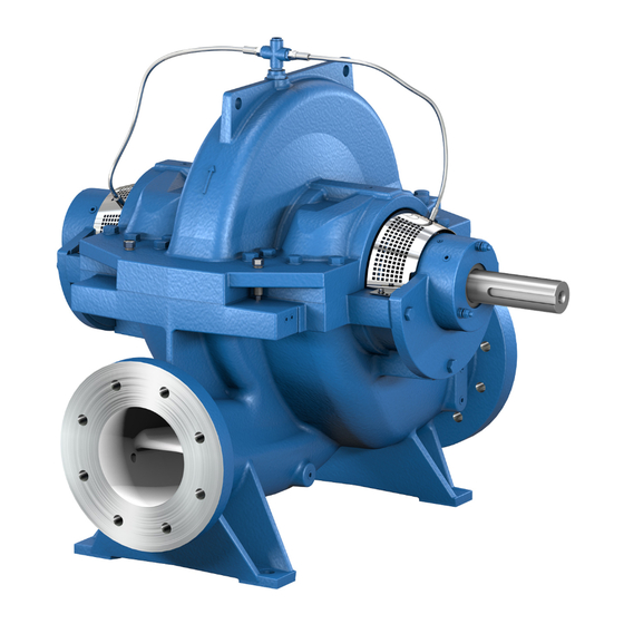
- Page 1 Axially Split Volute Casing Pump Omega / Omega V Horizontal Installation Type 3E Vertical Installation Types DB, DK, DP, DJ Installation/Operating Manual Mat. No.: 01059616...
- Page 2 All rights reserved. The contents provided herein must neither be distributed, copied, reproduced, edited or processed for any other purpose, nor otherwise transmitted, published or made available to a third party without the manufacturer's express written consent. Subject to technical modification without prior notice. © KSB SE & Co. KGaA, Frankenthal 2023-04-25...
-
Page 3: Table Of Contents
Aligning the pump and motor ........................ 38 5.6.1 Aligning the motor with adjusting screws .................. 38 5.6.2 Aligning the motor without adjusting screws ................ 40 Permissible forces and moments at the pump nozzles ................ 41 Omega / Omega V 3 of 106... - Page 4 Vertically installed pump, installation type DB ................ 92 9.2.4 Vertically installed pump, installation type DK................ 95 9.2.5 Vertically installed pump, installation type DP ................ 98 EU Declaration of conformity...................... 101 Certificate of Decontamination...................... 102 Index .............................. 103 Omega / Omega V 4 of 106...
-
Page 5: Glossary
Machine without drive, additional components or accessories Pump set Complete pump set consisting of pump, drive, additional components and accessories Suction lift line/suction head line The pipeline which is connected to the suction nozzle Omega / Omega V 5 of 106... -
Page 6: General
In the event of damage, immediately contact your nearest KSB service facility to maintain the right to claim under warranty. 1.2 Installation of partly completed machinery To install partly completed machinery supplied by KSB refer to the sub-sections under Servicing/Maintenance. -
Page 7: Symbols
In conjunction with one of the signal words this symbol indicates a hazard involving electrical voltage and identifies information about protection against electrical voltage. Machine damage In conjunction with the signal word CAUTION this symbol indicates a hazard for the machine and its functions. Omega / Omega V 7 of 106... -
Page 8: Safety
Deficits in knowledge must be rectified by means of training and instruction provided by sufficiently trained specialist personnel. If required, the operator can commission the manufacturer/supplier to train the personnel. Training on the pump (set) must always be supervised by technical specialist personnel. Omega / Omega V 8 of 106... -
Page 9: Consequences And Risks Caused By Non-Compliance With This Manual
▪ Only perform work on the pump set when it has been disconnected from the power supply (de-energised). ▪ The pump (set) must have cooled down to ambient temperature. ▪ Pump pressure must have been released and the pump must have been drained. Omega / Omega V 9 of 106... -
Page 10: Unauthorised Modes Of Operation
The pump complies with the requirements of type of protection constructional safety "c" to ISO 80079-37. Shaft coupling An EC manufacturer's declaration is required for the shaft coupling; the shaft coupling must be marked accordingly. Motor The motor must be considered separately. Omega / Omega V 10 of 106... -
Page 11: Temperature Limits
If the pump is to be operated at a higher temperature, the data sheet is missing or if the pump is part of a pool of pumps, contact KSB for the maximum permissible operating temperature. 2.9.3 Repair Special regulations apply to repair work on explosion-proof pumps. -
Page 12: Transport/Storage/Disposal
1. On transfer of goods, check each packaging unit for damage. 2. In the event of in-transit damage, assess the exact damage, document it and notify KSB or the supplying dealer and the insurer about the damage in writing immediately. - Page 13 Transporting the pump with base frame (figure 0 bare-shaft pump) ▪ Motor size 315 and larger ▪ Total weight (of the pump set) more than 1500 kg Transporting the pump vertically (installation types DB and DK) Omega / Omega V 13 of 106...
-
Page 14: Storage/Preservation
▷ Observe the weights indicated. CAUTION Damage during storage due to humidity, dirt or vermin Corrosion/contamination of pump (set)! ▷ For outdoor storage cover the pump (set) and accessories with waterproof material and protect against condensation. Omega / Omega V 14 of 106... -
Page 15: Return To Supplier
4. Always complete and enclose a certificate of decontamination when returning the pump. Indicate any safety measures and decontamination measures taken. (ð Section 11, Page 102) NOTE If required, a blank certificate of decontamination can be downloaded from the following web site: www.ksb.com/certificate_of_decontamination Omega / Omega V 15 of 106... -
Page 16: Disposal
2. Separate and sort the pump materials, e.g. by: - Metals - Plastics - Electronic waste - Greases and other lubricants 3. Dispose of materials in accordance with local regulations or in another controlled manner. Omega / Omega V 16 of 106... -
Page 17: Description Of The Pump (Set)
4.2 Product information as per Regulation No. 1907/2006 (REACH) For information as per European chemicals regulation (EC) No. 1907/2006 (REACH) see https://www.ksb.com/en-global/company/corporate-responsibility/reach. 4.3 Designation Example: Omega V 150 - 460 A GB P M Table 6: Designation key Code Description Omega... -
Page 18: Name Plate
4 Description of the Pump (Set) 4.4 Name plate KSB SE & Co. KGaA Johann-Klein-Straße 9 67227 Frankenthal Deutschland 2022 Omega 250 - 600 A P-No. 9974xxxx78 / 000100 Q 1050 m 120 m SNr. 24 15 26 n 1475 1/min Gew. 1090 kg Mat.-No. -
Page 19: Configuration And Function
Surface sound pressure level as per ISO 3744 and DIN EN ISO 20361 . valid for a pump operating range of Q/ QBEP = 0.8 - 1.1 and non-cavitating operation. If noise levels are to be guaranteed: Add +3 dB for measuring and constructional tolerance. The values indicated do not apply to operation on a frequency inverter. Omega / Omega V 19 of 106... - Page 20 Spatial average; as per ISO 3744 and DIN EN ISO 20361; valid for pump operation in the Q/QBEP = 0.8 - 1.1 range and for non-cavitating operation. If noise levels are to be guaranteed: Add +3 dB for measuring and constructional tolerance. The values indicated do not apply to operation on a frequency inverter. Omega / Omega V 20 of 106...
-
Page 21: Scope Of Supply
▪ Weight of the shipping unit base frame with pump and motor: See weight indicated on the base frame. NOTE Some individual components weigh more than 25 kg. Check the indicated weights. (ð Section 9.1, Page 85) (ð Section 1.4, Page 6) Omega / Omega V 21 of 106... -
Page 22: Installation At Site
▷ The mounting surface must be set, even, and level. ▷ Observe the weights indicated. 1. Check the structural requirements. All structural work required must have been prepared in accordance with the dimensions stated in the outline drawing/general arrangement drawing. Omega / Omega V 22 of 106... -
Page 23: Installing The Pump Set
▷ Observe the information given for the individual components regarding weights, centre of gravity and fastening points. ▷ Observe the applicable local accident prevention regulations. ▷ Use suitable, approved lifting accessories. Fig. 4: Pump and motor on a common base frame Omega / Omega V 23 of 106... - Page 24 For lifting and aligning observe the transport instructions. (ð Section 3.2, Page 12) The position of the pump on the base frame must not be changed during this alignment. After the curing time, slightly tighten the chemical anchors (4). Omega / Omega V 24 of 106...
- Page 25 Fig. 6: Dimensions Table 9: Chemical anchor dimensions Size [mm] [Nm] × l M10 × 130 M12 × 160 M16 × 190 M20 × 260 M24 × 300 M30 × 380 Minimum strength class C25/30 SW = Width across flats Mounting accessories of the respective manufacturer are required. Omega / Omega V 25 of 106...
- Page 26 Align the shafts with each other. Mount the motor as described in the motor manufacturer's operating manual. 13. Connect the piping to the pump without transmitting any stresses or strains. (ð Section 5.4, Page 36) 14. Align the coupling as described in the coupling manufacturer’s operating manual. Omega / Omega V 26 of 106...
-
Page 27: Dj Installation
▷ Observe the applicable local accident prevention regulations. ▷ Use suitable, approved lifting accessories. Fig. 8: Pump on its own foot (baseplate), drive on a different construction level Omega / Omega V 27 of 106... - Page 28 7. Grout the recesses for the foundation blocks with quick-setting, low-shrinkage concrete 8. When the concrete has set, tighten the hexagon head bolts (2). 9. Connect the piping to the pump without transmitting any stresses or strains. (ð Section 5.4, Page 36) Minimum strength class C25/30 Omega / Omega V 28 of 106...
-
Page 29: Dj Installation With Universal-Joint Shaft
Risk of injury by rotating shafts! ▷ Always operate the pump set with a coupling guard. If the customer specifically requests not to include a coupling guard in KSB's delivery, then the operator must supply one! ▷ Observe all relevant regulations for selecting a coupling guard. - Page 30 (ð Section 5.4, Page 36) 10. Mount the motor on the drive lantern as described in the motor manufacturer's operating instructions. 11. Align the coupling as described in the coupling manufacturer’s operating manual. Minimum strength class C25/30 Omega / Omega V 30 of 106...
-
Page 31: Dp Installation
▷ Observe the information given for the individual components regarding weights, centre of gravity and fastening points. ▷ Observe the applicable local accident prevention regulations. ▷ Use suitable, approved lifting accessories. Fig. 12: Pump on foot (baseplate), drive on support frame Omega / Omega V 31 of 106... - Page 32 5. Align the pump horizontally using the adjusting screws (2) and a suitable tool (e.g. spirit level) placed on the shaft and discharge nozzle. The maximum permissible deviation is 0.2 mm/m. 6. Align the pump with the piping. Omega / Omega V 32 of 106...
- Page 33 6. Insert the mortar cartridges into the drilled holes. Observe the curing times of the mortar cartridges. 7. Insert the threaded bolts of the chemical anchors into the corresponding drilled holes with a suitable tool (e.g. impact drill, hammer drill). Omega / Omega V 33 of 106...
- Page 34 [mm] [Nm] × l M10 × 130 M12 × 160 M16 × 190 M20 × 260 M24 × 300 M30 × 380 Refer to the general arrangement drawing for the required concrete quality. SW = Width across flats Mounting accessories of the respective manufacturer are required. Omega / Omega V 34 of 106...
- Page 35 8. Grout the recesses for the foundation rails with quick-setting, low-shrinkage concrete 9. When the concrete has set, the motor can be fastened to the support frame. Observe the motor manufacturer’s product literature. Omega / Omega V 35 of 106...
-
Page 36: Connecting The Piping
1. Thoroughly clean, flush and blow through all vessels, pipelines and connections (especially of new installations). 2. Before installing the pump in the piping, remove any flange covers on the suction and discharge nozzles of the pump. Omega / Omega V 36 of 106... -
Page 37: Enclosure/Insulation
Failure to re-install or re-activate protective devices Risk of injury from moving parts or escaping fluid! ▷ As soon as the work is completed, re-install and/or re-activate any safety- relevant and protective devices. Omega / Omega V 37 of 106... -
Page 38: Aligning The Pump And Motor
▷ Also check the coupling of pump sets supplied with pump and motor mounted on the same baseplate. 5.6.1 Aligning the motor with adjusting screws Fig. 18: Aligning the motor with adjusting screws Hexagon head bolt Adjusting screw Locknut Omega / Omega V 38 of 106... - Page 39 Risk of injury by rotating shafts! ▷ Always operate the pump set with a coupling guard. If the customer specifically requests not to include a coupling guard in KSB's delivery, then the operator must supply one! ▷ Observe all relevant regulations for selecting a coupling guard.
-
Page 40: Aligning The Motor Without Adjusting Screws
Risk of injury by rotating shafts! ▷ Always operate the pump set with a coupling guard. If the customer specifically requests not to include a coupling guard in KSB's delivery, then the operator must supply one! ▷ Observe all relevant regulations for selecting a coupling guard. -
Page 41: Permissible Forces And Moments At The Pump Nozzles
Mx / My / Mz Fx / Fy / Fz Mx / My / Mz [Nm] [Nm] [Nm] 080-210 1120 1520 080-270 1120 1520 080-370 1120 1520 100-250 1000 1400 1900 1330 100-310 1000 1400 1900 1330 Omega / Omega V 41 of 106... -
Page 42: Auxiliary Connections
Malfunction of the pump! ▷ Refer to the general arrangement drawing, the piping layout and pump markings (if any) for the quantity, dimensions and locations of auxiliary connections. ▷ Use the auxiliary connections provided. Omega / Omega V 42 of 106... - Page 43 Applies to sizes 100 - 375, 150 - 290, 150 - 360, 150 - 605, 200 - 420, 200 - 520, 200 - 670, 250 - 600, 250 - 800, 300 - 300, 300 - 435, 300 - 560, 300 - 700, 300 - 860, 350 - 360, 350 - 430, 350 - 510 Omega / Omega V 43 of 106...
-
Page 44: Connection To Power Supply
▷ Make sure that the connection between pump and baseplate is electrically conductive. ▷ Screws, bolts, nuts and shims must not be coated or the coating must be removed. ▷ Provide potential equalisation between the pump set and the foundation. Omega / Omega V 44 of 106... -
Page 45: Checking The Direction Of Rotation
3. If the motor runs in the wrong direction of rotation, check the electrical connection of the motor and the control system, if applicable. 5.11 Removing the transport lock This type of transport lock is only used for vertical pumps with a product-lubricated plain bearing. Omega / Omega V 45 of 106... - Page 46 5 Installation at Site 901.17 Fig. 24: Transport lock 1. Undo bolt 901.17 at cover 160. 2. Connect a flushing line to the drilled hole in cover 160. Omega / Omega V 46 of 106...
-
Page 47: Commissioning/Start-Up/Shutdown
If this is not the case, the shut-off element in the discharge line must be closed. 5. Fully open all auxiliary connections (barrier fluid, flushing liquid, etc). Omega / Omega V 47 of 106... -
Page 48: Start-Up
ü The system piping has been cleaned. ü Pump, suction line and inlet tank, if any, have been vented and primed with the fluid to be pumped. ü The lines for priming and venting have been closed. Omega / Omega V 48 of 106... -
Page 49: Checking The Shaft Seal
▷ No leakage: Switch off the pump set immediately. ▷ It is not recommended to operate pump sets with gland packings in combination with a frequency inverter / variable speed system. Omega / Omega V 49 of 106... -
Page 50: Shutdown
2. Switch off the motor and make sure the pump set runs down smoothly to a standstill. NOTE If the discharge line is equipped with a non-return or check valve, the shut-off element may remain open provided that the system conditions and system regulations are considered and observed. Omega / Omega V 50 of 106... -
Page 51: Operating Limits
The maximum operating pressure depends on the pump size, pump material and nominal pressure of the flange design. Neither the material/size-dependent maximum pressure indicated in the data sheet nor the maximum nominal flange pressure must be exceeded. Omega / Omega V 51 of 106... -
Page 52: Hydraulic Operating Range
If the pump set is operated outside its operating limits or system-related changes occur, check the NPSH values. If necessary, consult your nearest customer service centre. Omega / Omega V 52 of 106... -
Page 53: Frequency Of Starts
Do not exceed the maximum permissible solids content specified in the data sheet. When the pump handles fluids containing abrasive substances, increased wear of the hydraulic system and shaft seal are to be expected. In this case, reduce the commonly recommended inspection intervals. Omega / Omega V 53 of 106... -
Page 54: Shutdown/Storage/Preservation
▷ As soon as the work is completed, properly re-install and re-activate any safety- relevant devices and protective devices. NOTE On pumps/pump sets older than 5 years we recommend replacing all elastomer seals. E.g. drinking water or demineralised water Omega / Omega V 54 of 106... -
Page 55: Servicing/Maintenance
Risk of injury by moving components and shock currents! ▷ Ensure that the pump set cannot be started unintentionally. ▷ Always make sure the electrical connections are disconnected before carrying out work on the pump set. Omega / Omega V 55 of 106... -
Page 56: Servicing/Inspection
NOTE All maintenance work, service work and installation work can be carried out by KSB Service or authorised workshops. Find your contact in the attached Addresses booklet or visit https://www.ksb.com/en-global/contact. - Page 57 ▪ Check the drive as described in the manufacturer's product literature. ▪ Check that the fitted coupling guard does not touch the coupling. ▪ Make sure that the earthing connection has been fitted and marked. E.g. drinking water or demineralised water Omega / Omega V 57 of 106...
-
Page 58: Inspection Work
Within the preferred operating range of 0.7 ≤ Q/QBEP ≤ 1.2 the vibration values of newly commissioned pumps with good system conditions (piping layout, approach flow at the pump, etc.) are below the boundary of zone A to DIN ISO 10816-7, i.e. below 4.2 mm/s rms. Omega / Omega V 58 of 106... - Page 59 ▪ Check and replace, if necessary: – bearings, casing wear ring, impeller wear ring, shaft protecting sleeve – impeller and shaft – Fit new sealing elements. Omega / Omega V 59 of 106...
- Page 60 0,45 0,22 0,26 150-360 0,45 0,22 0,26 150-460 0,45 0,22 0,26 150-605 0,45 0,22 0,26 200-320 0,24 0,28 200-330 0,25 0,29 200-420 0,24 0,28 200-520 0,24 0,28 200-670 0,24 0,28 250-370 0,24 0,28 Omega / Omega V 60 of 106...
- Page 61 CAUTION Temporary storage of the pump set too long Formation of deposits or condensate, resinification or leakage of grease! ▷ Replace the complete rolling element bearings before returning the pump set to service. Omega / Omega V 61 of 106...
-
Page 62: Drainage/Cleaning
▷ Always have repair work and maintenance work performed by specially trained, qualified personnel. WARNING Improper lifting/moving of heavy assemblies or components Personal injury and damage to property! ▷ Use suitable transport devices, lifting equipment and lifting tackle to move heavy assemblies or components. Omega / Omega V 62 of 106... -
Page 63: Preparing The Pump Set
NOTE Vertical installation For dismantling a vertically installed pump, the complete pump has to be removed and placed in a horizontal position. Then, the complete rotor can be removed and dismantled. Omega / Omega V 63 of 106... - Page 64 Remove the rail. 4. Remove stud 904.02. 5. Undo screwed connection 901.12 between the pump and foot 182. Lift up the pump and place it down in a horizontal position on a suitable surface. Omega / Omega V 64 of 106...
- Page 65 7. Suspend volute casing 102 from the lifting equipment and secure it. 8. Undo screwed connection 901.12 between the pump and foot 182. Lift up the pump and place it down in a horizontal position on a suitable surface. Omega / Omega V 65 of 106...
- Page 66 8. Suspend volute casing 102 from the lifting equipment and secure it. 9. Undo screwed connection 901.12 between the pump and foot 182. Lift up the pump and place it down in a horizontal position on a suitable surface. Omega / Omega V 66 of 106...
- Page 67 Remove the rail. 7. Remove stud 904.02. 8. Undo screwed connection 901.12 between the pump and foot 182. Lift up the pump and place it down in a horizontal position on a suitable surface. Omega / Omega V 67 of 106...
-
Page 68: Opening The Volute Casing
2. Press the bearing housing out of the centring hub of the volute casing. Use suitable lifting equipment, e.g. looped ropes, to lift the rotor out of the lower casing half and securely place it down in a horizontal position. Only for mechanical seal Omega / Omega V 68 of 106... -
Page 69: Dismantling The Rotor
524.01. 6. Remove nuts 920.05, bearing housing 350.01 with spacer ring 550.02 and circlip 932 as well as spacer ring 550.01. 7. Pull off bearing cover 360 and deep groove ball bearing 321. Omega / Omega V 69 of 106... -
Page 70: Reassembling The Pump Set
Damage to the pump! ▷ Reassemble the pump (set) in accordance with the general rules of sound engineering practice. ▷ Use original spare parts only. Always observe the safety instructions and information. (ð Section 2.7, Page 9) Omega / Omega V 70 of 106... -
Page 71: Installing The Rotor
2. Fit keys into the keyways of pump shaft 211. 3. Fit impeller 234. Check that the direction of rotation of the impeller is correct! Fig. 34: Direction of rotation of the impeller Omega / Omega V 71 of 106... - Page 72 7.5.2.1 Installing the mechanical seal Pump set with KSB mechanical seal ü The individual parts have been placed in a clean and level assembly area. ü All dismantled parts have been cleaned and checked for wear.
- Page 73 423.02) on shaft protecting sleeve 524. 2. Heat up deep groove ball bearing 321 and pull it onto pump shaft 211. Prevent any one-sided pressure and impacts. Secure the bearing with disc 550.01 and circlip 932. Omega / Omega V 73 of 106...
- Page 74 Applies to the following sizes only: 200-330 Applies to the following sizes only: 250-450 Applies to the following sizes only: 250-800, 300-560, 300-700, 350-430, 350-510 and 400-500 Applies to the following sizes only: 300-860 Omega / Omega V 74 of 106...
- Page 75 3. Align the rotor. Make sure that the fastening studs are correctly inserted into the pump casing. 4. Observe the position of pins 561.01. 561.01 Fig. 37: Position of pins 561.01 Casing wear rings Omega / Omega V 75 of 106...
-
Page 76: Mounting The Pump Set On The Baseplate
Refer to the motor manufacturer's product literature. 901.14 920.2 Gland follower nuts As necessary for the required leakage (ð Section 6.1.4, Page 49) Observe the following values: Applies to fixed bearings. For horizontal installation: non-drive end; for vertical installation: drive end Omega / Omega V 76 of 106... -
Page 77: Spare Parts Stock
▪ Part No. and description (ð Section 9.2, Page 86) ▪ Quantity of spare parts ▪ Shipping address ▪ Mode of dispatch (freight, mail, express freight, air freight) For µTotal = 0.14 and 90 % of the minimum yield strength Omega / Omega V 77 of 106... -
Page 78: Recommended Spare Parts Stock For 2 Years' Operation To Din 24296
Mechanical seal installation kit 457.2 Neck ring ✘ ✘ ✘ Seal cover ✘ ✘ ✘ 525.2 Spacer sleeve ✘ ✘ ✘ Gland packing For vertical installation with product-lubricated plain bearing, halve the number of spare parts. Omega / Omega V 78 of 106... - Page 79 30 % Stuffing box insert ✘ ✘ ✘ 12 12 16 30 % Neck ring 12 12 16 30 % ✘ ✘ ✘ Lantern ring ✘ ✘ ✘ 12 12 16 30 % Omega / Omega V 79 of 106...
-
Page 80: Trouble-Shooting
▪ Install pump at a lower level. ▪ Alter suction/inlet line, if piping losses are too high. Pump pressure must be released before attempting to remedy faults on parts which are subjected to pressure. Omega / Omega V 80 of 106... - Page 81 ✘ Assembly bolts/sealing elements ▪ Check. ▪ Re-tighten the bolts. ▪ Fit new sealing elements. ▪ Check pipeline connections and secure fixing of pump; improve fixing of pipelines, if necessary. Omega / Omega V 81 of 106...
- Page 82 - Insufficient or excessive quantity of ▪ Clean the bearings. ✘ lubricant or unsuitable lubricant ▪ Top up, reduce or change lubricant. ▪ Check oil lubrication system ▪ Check oil supply If any Omega / Omega V 82 of 106...
- Page 83 - Shaft is out of true. ▪ Replace. ✘ ✘ ✘ ✘ - Impeller rubs against casing ▪ Check rotor. components. ▪ Check impeller position. ▪ Verify that piping has been connected without transmitting any stresses or strains. Omega / Omega V 83 of 106...
-
Page 84: Explanation Of Faults
Q. The operating point B is given by the intersection between the system curve H and the pump's characteristic curve H. If the cause of a fault or malfunction is unclear, consult your nearest KSB service centre. NPSH NPSH Fig. 38: Adjusting to the duty point... -
Page 85: Related Documents
< 25 300-300 < 25 300-435 < 25 300-560 1065 < 25 300-700 1295 < 25 300-860 2064 < 25 350-360 < 25 350-430 1050 < 25 350-510 < 25 400-500 1595 < 25 Omega / Omega V 85 of 106... -
Page 86: General Assembly Drawing With List Of Components
Fig. 39: General assembly drawing for horizontal installation * For explosion-proof versions: labyrinth ring 423.02 ** For explosion-proof versions: labyrinth ring 423.01 *** Not for explosion-proof versions **** Not for versions with KSB mechanical seal 4OM Omega / Omega V 86 of 106... - Page 87 9 Related Documents Detail drawing: Detail drawing: Gland packing, standard Gland packing for Omega FXF 200-330, FXF 200-520, FXF 200-670, FXF 250-450, FXF 250-600 458 461 524.01 455 452 412.01 902.01 920.02 411.01 A = UL certification B = FM certification...
- Page 88 Hexagon head bolt Mechanical seal 902.01 Stud Shaft seal housing 903.01/.02/.03/.04/.08 Screw plug Gland follower Grub screw Stuffing box insert 920.02/.03/.05 457.02 Neck ring Circlip Lantern ring 940.01/.02/.03 Gland packing Spring Seal cover Omega / Omega V 88 of 106...
-
Page 89: Vertically Installed Pump, Installation Type Dj
Fig. 40: General assembly drawing for installation type DJ * For explosion-proof versions: labyrinth ring 423.02 ** For explosion-proof versions: labyrinth ring 423.01 *** Not for explosion-proof versions **** Not for versions with KSB mechanical seal 4OM Omega / Omega V 89 of 106... - Page 90 901.01 5203 Table 24: List of components Part No. Description Part No. Description Volute casing Impeller wear ring Cover 524.01/.02 Shaft protecting sleeve Foot 525.01/.02 Spacer sleeve Pump shaft Bearing bush Impeller 550.01/.02/.03/.04/.05 Disc Omega / Omega V 90 of 106...
- Page 91 904.02 Grub screw Gland follower 914.01 Hexagon socket head cap screw Stuffing box insert 920.01/.02/.05/.08 457.02 Neck ring 930.01 Safety device Lantern ring Circlip Gland packing 940.02/.03 Seal cover Spring Casing wear ring Omega / Omega V 91 of 106...
-
Page 92: Vertically Installed Pump, Installation Type Db
Fig. 41: General assembly drawing for installation type DB * For explosion-proof versions: labyrinth ring 423.02 ** For explosion-proof versions: labyrinth ring 423.01 *** Not for explosion-proof versions **** Not for versions with KSB mechanical seal 4OM Omega / Omega V 92 of 106... - Page 93 Part No. Description Part No. Description Volute casing Casing wear ring Cover Impeller wear ring Foot 524.01/.02 Shaft protecting sleeve Pump shaft 525.01/.02 Spacer sleeve Impeller 531.01 Locking sleeve Radial ball bearing Bearing bush Omega / Omega V 93 of 106...
- Page 94 Shaft seal housing 904.02 Grub screw Gland follower 914.01 Hexagon socket head cap screw Stuffing box insert 920.01/.02/.05/.08/.12 457.02 Neck ring 930.01 Safety device Lantern ring Circlip Gland packing 940.02/.03 Seal cover Spring Omega / Omega V 94 of 106...
-
Page 95: Vertically Installed Pump, Installation Type Dk
Fig. 42: General assembly drawing for installation type DK * For explosion-proof versions: labyrinth ring 423.02 ** For explosion-proof versions: labyrinth ring 423.01 *** Not for explosion-proof versions **** Not for versions with KSB mechanical seal 4OM Omega / Omega V 95 of 106... - Page 96 Part No. Description Part No. Description Volute casing Casing wear ring Cover Impeller wear ring Foot 524.01/.02 Shaft protecting sleeve Support foot 525.01/.02 Spacer sleeve Pump shaft 531.01 Locking sleeve Impeller Bearing bush Omega / Omega V 96 of 106...
- Page 97 904.02 Grub screw Shaft seal housing 914.01 Hexagon socket head cap screw Gland follower 920.01/.02/.05/.08/.12 Stuffing box insert 930.01 Safety device 457.02 Neck ring Circlip Lantern ring 940.02/.03 Gland packing Spring Seal cover Omega / Omega V 97 of 106...
-
Page 98: Vertically Installed Pump, Installation Type Dp
Fig. 43: General assembly drawing for installation type DP * For explosion-proof versions: labyrinth ring 423.02 ** For explosion-proof versions: labyrinth ring 423.01 *** Not for explosion-proof versions **** Not for versions with KSB mechanical seal 4OM Omega / Omega V 98 of 106... - Page 99 901.01 5203 Table 27: List of components Part No. Description Part No. Description Volute casing Impeller wear ring Cover 524.01/.02 Shaft protecting sleeve Foot 525.01/.02 Spacer sleeve Pump shaft Bearing bush Impeller 550.01/.02/.03/.04/.05/.17 Disc Omega / Omega V 99 of 106...
- Page 100 904.02 Grub screw Gland follower 914.01 Hexagon socket head cap screw Stuffing box insert 920.01/.02/.05/.08 457.02 Neck ring 930.01 Safety device Lantern ring Circlip Gland packing 940.02/.03 Seal cover Spring Casing wear ring Omega / Omega V 100 of 106...
-
Page 101: Eu Declaration Of Conformity
10 EU Declaration of conformity 10 EU Declaration of conformity Manufacturer: KSB SE & Co. KGaA Johann-Klein-Straße 9 67227 Frankenthal (Germany) The manufacturer herewith declares that the product: Omega, Omega V KSB order number: ....................▪ is in conformity with the provisions of the following directives / regulations as amended from time to time: –... -
Page 102: Certificate Of Decontamination
We confirm that the above data and information are correct and complete and that dispatch is effected in accordance with the relevant legal provisions....................................Place, date and signature Address Company stamp Required field Omega / Omega V 102 of 106... -
Page 103: Index
Causes and remedies 80 Storage 15 Filter 37, 61 Frequency of starts 53 Temperature limits 11 Gland packing 49 Warnings 7 Warranty claims 6 Impeller type 18 Installation at site 22 Intended use 8 Key to safety symbols/markings 7 Maintenance 56 Mechanical seal 49 Name plate 18 Noise characteristics 19, 20 Omega / Omega V 103 of 106... - Page 106 KSB SE & Co. KGaA Johann-Klein-Straße 9 • 67227 Frankenthal (Germany) Tel. +49 6233 86-0 www.ksb.com...
Need help?
Do you have a question about the Omega and is the answer not in the manual?
Questions and answers