Table of Contents
Advertisement
Available languages
Available languages
Quick Links
Wilo-ER 2/ ER 3-4
D
Einbau- und Betriebsanleitung
GB
Installation and Operating Instructions
F
Notice de montage et de mise en service
NL
Montage- en bedieningsvoorschriften
E
Instrucciones de instalación y servicio
I
Istruzioni di montaggio, uso e manutenzione
H
Beépítési és üzemeltetési utasítás
PL
Instrukcja montażu i obsługi
CZ
Návod k montáži a obsluze
RUS
montaΩu
Instrukciä po
i qkspluataciœ
Advertisement
Table of Contents

Related Manuals for Wilo ER 2


Summary of Contents for Wilo ER 2
- Page 1 Wilo-ER 2/ ER 3-4 Einbau- und Betriebsanleitung Beépítési és üzemeltetési utasítás Installation and Operating Instructions Instrukcja montażu i obsługi Notice de montage et de mise en service Návod k montáži a obsluze Montage- en bedieningsvoorschriften montaΩu Instrukciä po i qkspluataciœ...
- Page 2 ® UNIDOMO Web: www.unidomo.de Telefon: 04621- 30 60 89 0 Mail: info@unidomo.com Öffnungszeiten: Mo.-Fr. 8:00-17:00 Uhr a member of DAIKIN group � Individuelle Beratung � Komplettpakete Kostenloser Versand Über 15 Jahre Erfahrung � � Hochwertige Produkte Markenhersteller � �...
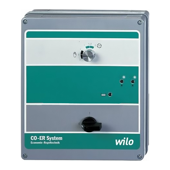
- Page 3 CO-ER System Economy Regeltechnik Fig. 1...
- Page 4 Fig. 2...
- Page 5 Fig. 3...
- Page 6 Fig. 4...
- Page 7 Fig. 5 Fig. 6...
-
Page 8: Table Of Contents
1. Allgemeines ........1. - Page 9 1. V‰eobecné informace ......28 2. Bezpeãnost ........28 3.
-
Page 11: Allgemeines
– Wasserversorgungsanlagen, – Feuerlöschanlagen. 4.2 Frontplatte des Schaltgerätes (Bild 1) 1.2 Angaben über das Erzeugnis Mit dem Schaltgerät ER 2/ER 3– 4 werden die Pumpen automatisch 1.2.1 Anschluß- und Leistungsdaten gesteuert. Die Frontplatte des Schaltkastens enthält folgende Schalter Anschlußspannungen: 3~400 V ± 10 %, 50/60 Hz bzw. -
Page 12: Aufstellung/Einbau
– Testlauf: Bei der Einstellung „Testlauf“ läuft jeweils eine Pumpe nach Ablauf von ca. 6 h ca. 15 s lang. Die Testlaufintervalle sind fest pro- Vor Inbetriebnahme der Pumpenanlage mit dem Schaltgerät ER 2/ grammiert und werden weder von den Laufzeiten der Pumpen noch ER 3-4 sind die in den Tabellen I und II aufgeführten Einstellungen für... - Page 13 DEUTSCH Tabelle I: Funktionen der Potentiometer und Hakenschalter (Bild 2/3) Schalter/Poti Funktionen Potentiometer zur Einstellung auf Motornennstrom: P1 für Pumpe 1 P2 für Pumpe 2 P3 für Pumpe 4 P4 für Pumpe 3 P8 für Nachlaufzeit nach Abschaltung der Pumpe (0 – 2 min) P9 für Zeitverzögerung für Abschaltung Wassermangel (0 –...
-
Page 14: General
4.2 Unit front panel (Fig. 1) Switch unit for the automatic control of low capacity pump units The ER 2/ER 3-4 control unit serves to automatically control a multi- consisting of 2 to 4 pumps in conjunction with pump set. The unit front panel contains the following switches or sig- –... -
Page 15: Siting/Installation
‘Pump Duty Cycling’ has been provided, meaning that on each new start of the plant the next successive pump assumes the base-load All functional adjustments on the ER 2/ER 3-4 control unit as laid out function. Duty changeover also takes place when one or more in Charts I and II must have been set prior to initially starting the pump(s) are continously running (approx. - Page 16 ENGLISH Chart I: Functions of potentiometers and hook switches (Fig. 2/3) Switch/Pot. Functions Potentiometer for FLC-settings: P1 for No. 1 pump P2 for No. 2 pump P3 for No. 4 pump P4 for No. 3 pump P8 to set pump stop time delay (0 – 2 min) P9 to set pump stop time delay on low water cut-out (0 –...
-
Page 17: Généralités
4.2 Platine avant du commutateur (Figure 1) Puissance de rupture max.: P2 ≤ 4 kW par pompe pour Le commutateur ER 2/ER 3–4 assure la gestion automatique des 3~400 V pompes. La platine avant du coffret de commande présente les com- P2 ≤... -
Page 18: Installation/Montage
6 Mise en service – Commutateur – Notice de montage et de mise en service Avant la mise en service de la pompe avec le commutateur ER 2/ ER 3–4, procéder aux réglages indiqués dans les tableaux I et II pour 5 Installation/Montage les différentes applications. - Page 19 FRANÇAIS Tableau I: Fonctions des crochets commutateurs et des potentiomètres (Figure 2/3) Commutateur/ Fonctions Potentiomètre Potentiomètres pour réglage sur le courant nominal du moteur: P1 pour la pompe 1 P2 pour la pompe 2 P3 pour la pompe 4 P4 pour la pompe 3 P8 pour réglage du temps de relance après déconnexion de la pompe (0 –...
-
Page 20: Algemeen
Schakelkast voor automatische pompbesturing van enkelpompen met 4.2 Vooraanzicht van de schakelkast (afb. 1) een klein vermogen. Met de schakelkast ER 2 /ER 3 – 4 worden de pompen automatisch – in waterverzorgingssystemen bestuurd. Het kastfront bevat de onderstaande schakelaars/aanwijzin- –... -
Page 21: Plaatsing/Inbouw
De pompwissel volgt Bij inbedrijfname van installaties met schakelkast ER 2/ER 3 – 4 dienen ook wanneer een of meerdere pompen voortdurend in bedrijf zijn. - Page 22 NEDERLANDS Tabel 1: functies van de haakschakelaar en potentiaalmeter (afb. 2/3) schakelaar/potentiaal functies potentiaalmeter voor instelling op nominale motorstroom P1 voor pomp 1 P2 voor pomp 2 P3 voor pomp 4 P4 voor pomp 3 P8 voor nalooptijd na uitschakeling van de pomp (0 – 2 min) P9 voor tijdvertragende uitschakeling bij watertekort (0 –...
-
Page 23: Generalidades
4.2 Panel frontal del cuadro de regulación (Figura 1) – Sistemas contra incendios El cuadro de regulación ER 2/ER 3–4 regula y controla las bombas de forma automática. El panel frontal del cuadro de regulación contiene Información sobre el producto los siguientes interruptores e indicaciones: 1.2.1 Datos de conexión y potencia... -
Page 24: Instalación Y Montaje
Antes de la puesta en marcha del grupo de presión con cuadro de el funcionamiento de prueba (Figura 2/3). regulación ER 2/ER 3–4, hay que efectuar los ajustes indicados en las tablas I y II para las distintas aplicaciones. 4.4 Suministro Cuadro de regulación... - Page 25 ESPAÑ0L Tabla I: Funciones de los potenciómetros y de los ganchos conmutadores (Figura 2/3) Gancho/ Funciones Potenciómetro Potentiómetro para el ajuste a la intensidad nominal de motor. P1 para bomba 1 P2 para bomba 2 P3 para bomba 4 P4 para bomba 3 P8 tiempo de retardo/func.
-
Page 26: Generalità
4.2 Pannello frontale quadro elettrico (figura 1) – impianti antincendio. Le pompe sono comandate automaticamente tramite il quadro elettri- Dati e caratteristiche tecniche co ER 2/ER 3–4. 1.2.1 Caratteristiche tecniche e prestazioni Sul frontale del quadro sono riportate le seguenti indicazioni: Tensione di rete: 3~400 V ±... -
Page 27: Montaggio/Installazione
Se nonostante questi interventi gli inconvenienti persistono Cavallottare i morsetti X0 della scheda come indicato sulle istruzioni richiedere l’intervento dell’installatore oppure del Servizio ”230 V”. Assistenza WILO. L1, L2, L3, PE: Rete elettrica 3~400 V, Cavallottare i morsetti X0 della scheda come indicato sulle istruzioni ”400 V”. - Page 28 ITALIANO Tabella I: funzioni del potenziometro e degli interruttori a gancio: (figura 2/3) Interruttore a gancio/ Funzioni potenziometro Potenziometro per l’impostazione della corrente del motore: P1 per la pompa 1 P2 per la pompa 2 P3 per la pompa 4 P4 per la pompa 3 P8 per la temporizzazione dello spegnimento pompa base (0 –...
-
Page 29: Általános Rész
– ivóvízellátó telephez, nyomás 7 bar. – tűzoltó telepekhez. 4.2 A kapcsoló-berendezés homloklapja (1. ábra) Az ER 2/ER 3–4 kapcsoló-berendezés a szivattyúkat automatikusan A termék adatai vezérli. A kapcsolódoboz homloklapján a következő kapcsolók és 1.2.1 Csatlakozási és teljesítmény adatok jelzések láthatók: Csatlakozó... -
Page 30: Felállítás/Beépítés
és így egy szivattyú idő előtti kiesését megelőzzük, előirányoztuk a ”szivattyúváltást”, amikoris a telep minden Mielőtt üzembe helyezzük az ER 2/ER 3-4 kapcsoló-berendezéssel újraindításakor a soron következő szivattyú veszi át az alapter- felszerelt szivattyútelepet, be kell állítani az I. és II. táblázatban leírt helési szivattyú... - Page 31 MAGYAR I. táblázat: A potenciométerek és kapcsolók működései (2/3. ábra) Kapcsoló/pot.méter Működések Potenciométerek a motor névleges árama beállítására P1 az 1. szivattyúhoz P2 a 2. szivattyúhoz P3 a 4. szivattyúhoz P4 a 3. szivattyúhoz P8 a szivattyú kikapcsolás késleltetéséhez (0 – 2 perc) P9 a vízhiány-lekapcsolás késleltetéséhez (2 s –...
-
Page 32: Dane Ogólne
4.2 Płyta czołowa urządzenia regulacyjnego (rys. 1) Max. moc przełączania: < 4 kW każdej pompy przy Za pomocą urządzenia ER 2/ER 3-4 realizuje się automatycznie 3~400 V sterowanie pomp. Płyta czołowa urządzenia zawiera następujące < 3 kW każdej pompy przy przełączniki i wskazania:... -
Page 33: Ustawienie / Monta
Przed uruchomieniem urządzenia pompowego z urządzeniem dorazowo po upływie 6-ciu godzin jedna z pomp uruchamiana jes sterującym ER 2/ER 3 – 4 należy dla danego zastosowania zrealizo- na okres ok. 15 s. wać nastawienia zgodne z tabelami I i II. - Page 34 POLSKI Tabela I: Funkcje potencjometrów i przełącznik hakowy (rys. 2/3) Przełącznik/Potencjometr Funkcje Potencjometry do ustawienia prądu znamionowego silników P1 dla pompy 1 P2 dla pompy 2 P3 dla pompy 4 P4 dla pompy 3 P8 dla czasu opóżnienia po wyłączeniu pompy (0 – 2 min.) P9 dla czasu opóżnienia przy braku wody (0 –...
-
Page 35: Eobecné Informace
Spínací přístroj pro automatické ovládání agregátů se dvěma až 4.2 Ovládací panel přístroje (obr. 1) čtyřmi čerpadly o menším výkonu pro Spínač ER 2/ER 3 – 4 ovládá čerpadla automaticky. Ovládací panel – vodovodní systémy, přistoje má tyto spínače a kontrolky: –... -
Page 36: Instalace / Montáï
6 Uvádění do provozu vní, bylo by více namáháno nežli čerpadla špičková. Pro rov- Před uvedením čerpacího agregátu se spínacím ER 2/ER 3 – 4 do noměrnější rozdělení doby chodu jednotlivých čerpadel a tím i pro provozu je třeba provést nastavení pro různé aplikace podle tab. I a prevenci výpadku některého čerpadla je zavedena funkce... - Page 37 ČESKY Tabulka I: Funkce potenciometrů a vidlicových spínačů (obr. 2/3) Spínač/Potenciometr Funkce Potenciometry pro nastavování jmenovitého proudu motoru: P1 pro čerpadlo 1 P2 pro čerpadlo 2 P3 pro čerpadlo 4 P4 pro čerpadlo 3 P8 pro doběh po vypnutí čerpadla (0 – 2 min) P9 pro zpožděni prí...
- Page 41 EN 61439-2 EN 61000-6-1:2007 EN 61000-6-3+A1:2011 EN 61000-6-2:2005 EN 61000-6-4+A1:2011 Digital unterschrieben von Holger Herchenhein Dortmund, Datum: 2017.10.19 18:57:09 +02'00' H. HERCHENHEIN WILO SE Senior Vice President - Group ITQ Nortkirchenstra e 100 44263 Dortmund - Germany N°2117872.02 (CE-A-S n°2540433)
- Page 42 ES/EK ATBILST BAS DEKLAR CIJU DIKJARAZZJONI TA’ KONFORMITÀ UE/KE WILO SEdeklar , ka izstr d jumi, kas ir nosaukti šaj deklar cij , atbilst šeit WILO SE jiddikjara li l-prodotti spe ifikati f’din id-dikjarazzjoni huma konformi uzskait to Eiropas direkt vu nosac jumiem, k ar atseviš u valstu likumiem,...
- Page 43 WILO SE estne prehlasuje, že výrobky ktoré sú predmetom tejto deklarácie, sú v súlade s požiadavkami nasledujúcich európskych direktív a WILO SE izjavlja, da so izdelki, navedeni v tej izjavi, v skladu z dolo ili odpovedajúcich národných legislatívnych predpisov: naslednjih evropskih direktiv in z nacionalnimi zakonodajami, ki jih vsebujejo: Nízkonapä...
- Page 44 WILO Pompa Sistemleri Jakarta Timur, 13950 Sistemas Hidraulicos Lda. San. ve Tic. A.S¸ T +62 21 7247676 4475-330 Maia 34956 İstanbul citrawilo@cbn.net.id T +351 22 2080350 T +90 216 2509400 bombas@wilo.pt wilo@wilo.com.tr Further subsidiaries, representation and sales offices on www.wilo.com Oktober 2018...
- Page 45 ® UNIDOMO Web: www.unidomo.de Telefon: 04621- 30 60 89 0 Mail: info@unidomo.com Öffnungszeiten: Mo.-Fr. 8:00-17:00 Uhr a member of DAIKIN group � Individuelle Beratung � Komplettpakete Kostenloser Versand Über 15 Jahre Erfahrung � � Hochwertige Produkte Markenhersteller � �...
- Page 46 WILO SE Nortkirchenstraße 100 D-44263 Dortmund Germany T +49(0)231 4102-0 F +49(0)231 4102-7363 wilo@wilo.com Pioneering for You www.wilo.com...
Need help?
Do you have a question about the ER 2 and is the answer not in the manual?
Questions and answers
Обратные клапана и задвижки станции с 2-мя насосами