
Related Manuals for Contemporary Controls BAST-221C


Summary of Contents for Contemporary Controls BAST-221C
- Page 1 BAST-221C BACnet Communicating Thermostat for Multi-Stage Relay Heating/Cooling/Ventilation BASstat Binary (B2-BW2) User Manual # UM-15090000-AA4...
- Page 2 Trademarks BASautomation, Contemporary Controls, and CTRLink are registered trademarks of Contemporary Control Systems, Inc. BACnet is a registered trademark of the American Society of Heating, Refrigerating and Air-Conditioning Engineers, Inc. Powered by Sedona Framework is a trademark of Tridium, Inc. Other product names may be trademarks or registered trademarks of their respective companies.
-
Page 3: Table Of Contents
Contents Introduction ......................4 Features and Benefits ..................4 Product Image and Main Features ..............6 Specifications ......................7 Inputs ......................... 7 Outputs ......................7 Communication ....................7 Electrical ......................7 Environmental ....................8 Electromagnetic Compatibility ................8 Mechanical (all dimensions are in mm) .............. 9 Installation ...................... -
Page 4: Introduction
1 Introduction The BAST-221C is a member of the BASstat BACnet Communicating Thermostat series. It provides multi-stage heating and cooling control in an attractive wall-mounted enclosure with a large LCD display. Intended for use with rooftop units (RTUs), the thermostat can control one or two stages of heating and one or two stages of Direct Expansion (DX) cooling. - Page 5 • Adjustable algorithm applied to multi-stage step control • Adjustable minimum on/off time staging for optimizing runtime • Effective run time accumulation for system runtime for energy consumption metering Full configurable control parameters such as deadband, proportional gain, integral rate, •...
-
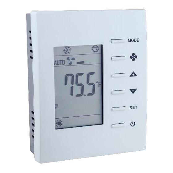
Page 6: Product Image And Main Features
Product Image and Main Features BASstat 221C-B2 and BASstat 221C-BW2 UM-15090000-AA4 Page 6... -
Page 7: Specifications
2 Specifications Inputs Item Description Temperature Display Range 14 to 140°F (-10 to 60°C) Temperature Display Resolution 0.1°F (0.1°C) Temperature Accuracy ±1.8°F (±1.0°C) with all outputs off Setpoint Range 32-122°F (0-60°C) in 0.5° (°F or °C) increments Remote Temperature Sensor Provision for NTC Type 3kΩ... -
Page 8: Environmental
-40°F to +85°F (-40°C to 30°C) Relative Humidity 5 to 95% non-condensing Electromagnetic Compatibility The BAST-221C complies with the following specifications and bears the CE mark in accordance with the provisions of the Electromagnetic Compatibility (EMC) Directive 2004/108/EC based on the following specifications: Standard... -
Page 9: Mechanical (All Dimensions Are In Mm)
Mechanical (all dimensions are in mm) Mounts directly onto wall, panel, standard 65×65mm junction box (hole pitch 60 mm) or standard 2×4-inch vertical junction box (hole pitch 83.5mm) Width: 94mm Height: 118mm Depth: 34mm UM-15090000-AA4 Page 9... - Page 10 UM-15090000-AA4 Page 10...
-
Page 11: Installation
3 Installation The BASstat is intended for surface-mount installation at eye-level on a wall, not subjected to direct sunlight or direct air movement. The display (top half) can be removed from its base by loosening the small Philips screw at the bottom of the display. There is no need to remove the screw. -
Page 12: Limited Power Source
Limited Power Source The BASstat thermostats accept 24VAC only with no more than 5VA of power consumption and should be powered by a limited power source complying with the requirements of the National Electric Code (NEC) article 725 or other international codes meeting the same intent of limiting the amount of power of the source. -
Page 13: Power Supply Precautions
Power Supply Precautions Internally, the BASstat utilizes a half-wave rectifier and therefore can share the same AC power source with other half-wave rectified devices. Sharing AC power with full-wave rectified devices is NOT recommended. Full-wave rectified devices usually require a dedicated AC power source that has a secondary elevated above ground. -
Page 14: Operation
4 Operation User Mode User-side comfort control is accomplished with six buttons – MODE (Heat, Cool, or Ventilate), FAN (Auto or Continuous), UP, DOWN, SET, and POWER. There are also options to lock select buttons or all buttons on the thermostat to limit user access if required in certain applications. - Page 15 User Mode Thermostat Operation Item Description Remarks Normal Display Display current room or set-point Use the (SP) parameter in temperature the Engineering Menu or [MSV6] Display Option for BW2 or [MSV7] Display Option for B2 model to choose Current room or Set- point temperature on display.
-
Page 16: Control Type
User Mode Flow Chart Control Type Control Type, System Mode and Algorithm Configuration Both binary thermostat models (B2 and BW2) support two different control types, selectable in Engineering Menu item (tyPE) or BACnet object [MSV8] Control Type for B2 model or [MSV7] Control Type for BW2 model. - Page 17 System modes available to the user are dependent on control type chosen from Engineering Menu (tyPE) or BACnet object [MSV7] Control Type for BW2 model and [MSV8] Control Type for B2 model. Dual Stage Heat and Cool with Auto Changeover - The default control type in the thermostat is set to Heat and Cool with Auto Changeover.
- Page 18 System Mode • The default control type is 2-stage cooling and heating with automatic changeover. This makes the thermostat operate fully stand-alone. Control Type can be selected in (tyPe) or [MSV7] or [MSV8]. Manual Changeover control type allows restriction of mode selection to Cool only or Heat only in applications where necessary.
- Page 19 (2)” the fan will run continuously after a control action. This feature is useful for thermostat models with multiple fan speeds. Fan Mode can be toggled between AUTO or CONTINUOS by using the FAN button • on the thermostat (user) or BACnet object [MSV0] Fan Mode (BACnet supervisor). By default, this value is set to “Auto(1)”, the AUTO icon is displayed and the fan will be controlled automatically.
-
Page 20: Engineering Mode Menu
Engineering Mode Menu Thermostat configuration can be performed using the engineering mode menu described below or BACnet objects using a BACnet client tool such as Contemporary Controls free BACnet Discovery Tool (BDT) It is highly suggested that engineering mode be operated by trained engineers only, because it is related to system parameters that will affect the control results. - Page 21 Engineering Menu Flow Chart MODE MODE E01 Setting MODE MODE E02 Setting No button pressed Previous for 10s under menu item selection MODE User Mode Press Up/down for over 5s UM-15090000-AA4 Page 21...
- Page 22 Engineering Menu Items Table – BW2 Model (BACnet/IP Wi-Fi) °C Scale °F Scale Step Item Mnemonic Description Default Range Default Range Deadband 0~10 0~18 0.5 (°C/°F) Unoccupied(ESI) cooling set point ESIC 25~35 82.5 77~95 1.0 (°C/°F) Unoccupied(ESI) heating set point ESIH 10.0~22.0 50.0~72.0...
- Page 23 °C Scale °F Scale Step Item Mnemonic Description Default Range Default Range 0: N.O. ESI (DI1) digital sensor contact definition 1: N.C. rE-C Not used rE-H Not used 0: built-in Present Temperature is getting from built-in 1: remote sense temperature Sensor, remote temperature 2: assigned sensor, or assigned through communication through...
- Page 24 °C Scale °F Scale Step Item Mnemonic Description Default Range Default Range 0: Cooling Only 1: C&H Manual tyPE 2: C&H Auto Control Type 3: Heating Only NOTE: Cool only and Heat only types disabled OPL2 Minimum Output for AO2 (not used) SPA2 Span Offset for AO2 (not used) CO2 Input Low Value (not used)
- Page 25 °C Scale °F Scale Step Item Mnemonic Description Default Range Default Range Phy3 MAC address 5th & 6th bytes hhhh hhhh h: 0~F in hex IP-1 1st byte of IPv4 address 0~255 0~255 IP-2 2nd byte of IPv4 address 0~255 0~255 IP-3 3rd byte of IPv4 address...
- Page 26 Add decimal values to lock multiples. Bold decimal number is Bit Definition: Decimal Value to Write: the example value to write to Lock object. Examples: 0: MODE button (dec=1) Unlock/enable all (0) – this will also enable ESI DI1 (add 64 to all values 1: DOWN button (dec=2) 2: UP button...
- Page 27 Engineering Menu Items Table – B2 Model (BACnet MS/TP) °C Scale °F Scale Step Item Mnemonic Description Default Range Default Range Deadband 0~10 0~18 0.5 (°C/°F) Unoccupied(ESI) cooling set point ESIC 25~35 82.5 77~95 1.0 (°C/°F) Unoccupied(ESI) heating set point ESIH 10.0~22.0 50.0~72.0...
- Page 28 °C Scale °F Scale Step Item Mnemonic Description Default Range Default Range 0: N.O. ESI (DI1) digital sensor contact definition 1: N.C. rE-C Not used rE-H Not used 0: built-in Present Temperature is getting from built-in 1: remote sense temperature Sensor, remote temperature 2: assigned sensor, or assigned through communication through...
- Page 29 °C Scale °F Scale Step Item Mnemonic Description Default Range Default Range dLyH 1 (minutes) Heating Short Cycle Heating Maximum Cycles per cycH 1 (cycles/hour) 2~255 2~255 Hour 0: Cooling Only 1: C&H Manual tyPE 2: C&H Auto Control Type 3: Heating Only NOTE: Cool only and Heat...
-
Page 30: Bacnet Objects And Network Configuration
°C Scale °F Scale Step Item Mnemonic Description Default Range Default Range engage test Reset all parameters including communication Press MODE to and control algorithm to the factory defaults Caution! load reset Press MODE to Exit Engineer Mode Menu exit engineering menu BACnet Objects and Network Configuration Transmission types (model dependent) - Page 31 Initial Configuration Initial communication configuration differs depending on whether you are using the BACnet MS/TP model (B2) or BACnet/IP over Wi-Fi model (BW2). All configuration parameters are settable through use of the buttons on thermostat by entering the Engineer Menu, or once installed on the BACnet network, configuration can also be altered using BACnet commands.
- Page 32 Reset Settings Thanks to its EEPROM, the BASstat will store configuration in the event of power loss. All settings can be reset back to default from Engineering Menu item (rSt). Use caution because once this item is selected (MODE button to select), all settings will be reset to their default values.
- Page 33 Once connected to the thermostat as an access point, open its web page by typing its default address of 192.168.0.1 with admin for username and no password. Web page pictured below will be presented for IP Network Configuration. The default IP configuration is shown below. After initial connection using laptop or tablet or smart phone, the Wi-Fi mode in the thermostat can be changed to Infrastructure mode.
- Page 34 • Passphrase should be a minimum of eight characters (maximum 15 characters), the more random the better. Use a mix of letters (uppercase and lowercase), numbers, and symbols. • Misspelling commonly used words and replacing some of the letters with numbers or symbols is a good practice and makes passwords difficult to guess.
- Page 35 The thermostat supports DHCP addressing and will acquire an IP address from the router/access point automatically if you chose Enable next to DHCP. If you chose Disable, you must assign an IP Address, Network Mask, and Gateway Address within the Wi-Fi router IP subnet manually.
- Page 36 Click OK on the confirmation message and wait 20 seconds for the reboot process to complete. While rebooting, the thermostat will display “DP” icon in the lower right corner to indicate it is in the process of searching and connecting to the AP. Once the “DP” stops flashing, the thermostat has successfully connected to Wi-Fi access point.
- Page 37 BACnet Object Table - B2 Model (BACnet MS/TP) Object name Type & Instance Object Property Range (Readable/Writable) BACnet Thermostat Device 100001 Model Name (R) Application Software Version (R) Object Identifier (R) Object Name (R/W) 32 characters (max.) Max_Master (R/W) 1~127 Type &...
- Page 38 Analog Input 2 Analog Input 2 Percentage AI 14 0~1000 (0.0%~100.0%) Value Value Analog Input 3 Analog Input 3 Percentage AI 15 0~1000 (0.0%~100.0%) Value Value °C :0~500 (0.0~50.0℃) Cooling Setpoint Cooling Temperature Set °F: 320~1220 Point AV 0 (32.0~122.0°F) Temperature Assigned Current -999~9999...
- Page 39 °C: -100~100 (- 10.0~10.0 Temperature Offset Offset for Current °C) AV 15 Temperature °F: -180~180 (-18.0~18.0 °F) Proportional Band- Stage Proportional Band or Stage °C :0~100 (00~10.0 °C) Width Width AV 16 °F: 0~180 (00~18.0 °F) °C :1~10 (0.1~1.0 °C) Stage Differential Stage Differential AV 17...
- Page 40 0~4194302 (Note: Changing this value Device Instance Device Instance needs to unlock modification AV 21 for communication parameters in advance. i.e. AV17=0~255 or 512~768. Please refer to LOCK(AV17) for details) -300~300 (-30.0~30.0 Humidity Offset Humidity Offset Value AV 22 %RH) Cooling Short Cycle Cooling Short Cycle Delay 1~3 Minutes...
- Page 41 Minimum Fan Minimum Fan Output at Auto Output Fan Mode (for Modulating 0%~Reg 51 Fan Application) AV 41 Maximum Fan Maximum Fan Output at Output Auto Fan Mode (for Reg 50~100% Modulating Fan Application) AV 42 Low Fan Speed Low Fan Speed Setting (for 0%~Reg 53 AV 43 Setting...
- Page 42 Dl 4 Status Status of Digital Input 4 0: Off, 1: On BI13 Dl 5 Status Status of Digital Input 5 0: Off, 1: On BI14 Dl 6 Status Status of Digital Input 6 0: Off, 1: On BI15 Dl 7 Status Status of Digital Input 7 0: Off, 1: On BI16...
- Page 43 Relay 2 Control On/Off Control of Relay 2 0: Off, 1: On (Cooling Stage 2) Relay 3 Control On/Off Control of Relay 3 0: Off, 1: On (Heating Stage 1) Relay 4 Control On/Off Control of Relay 4 0: Off, 1: On BV10 (Heating Stage 2) Relay 5 Control...
- Page 44 3: CO2 & Time 4: SP & CO2 5: T & RH 6: T & Valve 1: Cool Only 2: 4-Pipe Cooling or Heating Manual Changeover 3: 4-Pipe Cooling and Heating Auto Changeover Control Type Control Type Selection MSV 8 4: Heating Only NOTE: Cool only and Heat only types disabled...
- Page 45 -999~9999: -99.9~999.9 Current Dew Point Current Dew Point AI 5 ℃/°F Current CO Current CO Reading AI 6 0~3000: 0~3000 ppm Reading Control Valve Control Valve Feedback AI 7 0~1000 (0.0%~100.0%) Feedback Modulating/ Modulating/ Floating Output 0~100: 0~100 % AI 8 Floating Output 1 Modulating/ Modulating/ Floating Output...
- Page 46 Integral-Cycle Integral Time and Output 0~500 (Sec.) AV 10 Time Cycle Time Analog Minimum Minimum Output Voltage in Output Digital Value When Reach 0~125 (LSB) Low Limit for AO1 AV 11 Span Offset Span Offset for AO1 -55~0 (LSB) AV 12 °C :0~500 (0.0~50.0℃) Low Setpoint Limit Low Limit for Set-Point...
- Page 47 Percentage of Modulating/ Control Out Floating Control Output 0~100 (0%~100%) Percentage AV 19 0~4194302 (Note: Changing this value needs to unlock modification for communication parameters in advance. Device Instance AV 20 Device Instance i.e. AV17=0~255 or 512~768. Please refer to LOCK(AV17) for details) UDP Port No UDP Port Number...
- Page 48 Analog Input High Analog Input High Value 0~1000 (0.0~100.0 %) AV 38 Value Humidity Input Low Humidity Input Low Value 0~1000 (0.0~100.0 Value AV 39 %RH) Humidity Input High 0~1000 (0.0~100.0 Value Humidity Input High Value %RH) AV 40 Minimum Fan Minimum Fan Output at Auto Output Fan Mode (for Modulating...
- Page 49 Relay 6 Status Status of Relay 6 0: Off, 1: On BI 8 Relay 7 Status Status of Relay 7 0: Off, 1: On BI 9 Dl 1 Status Status of Digital Input 1 0: Off, 1: On BI10 Dl 2 Status Status of Digital Input 2 0: Off, 1: On BI11...
- Page 50 Contact Definition 0: N.O. BV 4 1: N.C. On-Off Control On/Off Status of Thermostat 0: Off, 1: On BV 5 0: °C Temperature Scale °C/ °F 1: °F BV 6 Relay 1 Control On/Off Control of Relay 1 0: Off, 1: On (Cooling Stage 1) Relay 2 Control On/Off Control of Relay 2...
- Page 51 Display Options LCD Display Options & CO2 MSV 6 3: CO2 & Time 4: SP & CO2 5: T & RH 6: T & Valve 1: Cooling Only 2: Cooling or Heating Manual Changeover 3: Cooling and Heating Auto Changeover (default) Control Type Control Type Selection MSV 7...
-
Page 52: Warranty
5 Warranty Contemporary Controls (CC) warrants this product to the original purchaser for two years from the product shipping date. Product returned to CC for repair is warranted for one year from the date the repaired product is shipped back to the purchaser or for the remainder of the original warranty period, whichever is longer. -
Page 53: Returning Products For Repair
Returning Products for Repair Return the product to the location where it was purchased by following the instructions at the URL below: www.ccontrols.com/rma.htm UM-15090000-AA4 Page 53... -
Page 54: Declaration Of Conformity
Information about the regulatory compliance of this product can be found at the URL below: www.ccontrols.com/compliance.htm United States China United Kingdom Germany Contemporary Control Contemporary Controls Contemporary Controls Contemporary Controls Systems, Inc. (Suzhou) Co. Ltd GmbH 2431 Curtiss Street 11 Huoju Road 14 Bow Court Fuggerstraße 1 B...
Need help?
Do you have a question about the BAST-221C and is the answer not in the manual?
Questions and answers