Advertisement
Quick Links
Advertisement

Related Manuals for Eaton Paramount Enclosure


Summary of Contents for Eaton Paramount Enclosure
- Page 1 ® Eaton Data Center Racks...
-
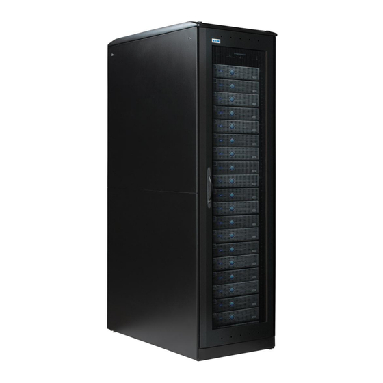
Page 3: Product Overview
Split rear doors (perforated or fan) 2,200 lb. static load Standard to advanced security options Segmented bays for co-location applications Tool-less adjustable rack-mount rails Field-reversible doors NuGrey, Black, Two-tone, or Custom Colors Custom configurations Lifetime warranty Pub Num: MN159002EN rev1.0 Paramount Enclosure Installation Guide... -
Page 4: Important Safety Information
Failure to adhere to the following warnings may cause personal injury or damage to your enclosure rack. 1. WARNING! Paramount Enclosure components can be very heavy. It is recommended that several people take part in the unpacking process. When lifting Paramount components or electronic equip- ment, there should be at least one person for every 40 lbs. -
Page 5: Installation Overview
“Field Assembled Components” section for any additional accessories that may require installation. Field Assembled Enclosures To meet the needs of some users, Wright Line may ship the Paramount Enclosure Frames in a partially disassembled state, requiring additional field assembly procedures. Refer to the “Field Assembled Enclosure Frames” section and the “Field Assembled Components”... - Page 6 5/16”-18 Self Locking 1/4”-20 Self Locking Nut Pan Head Thread Pan Head Screw Forming Screw #18242 #2232X #87442 #84397 #10-24 Self Locking Nut Hole Plug #10-32 x 5/8” Screw #10-32 Clip Nut w/Nylon Washer Pub Num: MN159002EN rev1.0 Paramount Enclosure Installation Guide...
-
Page 7: Standard Shipping Pallet
Use extreme caution in the de-skidding process to ensure safety. If a Paramount enclosure is to be populated with electronic equipment and then re- shipped to another location, the use of a Heavy Duty Pallet is recommended. The standard shipping pallet shown below is intended for the shipment of an empty enclosure. - Page 8 5. Use two or more people to roll the enclosure off of the pallet. Do not push on the center of doors or side pan- els. Enclosure Corrugated packaging Ramp Ramp Ramp Band Hole Figure 4-4 Heavy duty pallet Figure 4-3 Enclosure Screws Shipping bracket Figure 4-6 Figure 4-5 Pub Num: MN159002EN rev1.0 Paramount Enclosure Installation Guide...
- Page 9 3. Unlock and open the rear door. Locate the six screws that attach the rear PTOC frame to the enclosure frame. Loosen the six screws to allow the rear frame to drop down to the functional position. Then re-tighten the screws. See figure 4-7. PTOC frame Screw Move down Figure 4-7 Pub Num: MN159002EN rev1.0 Paramount Enclosure Installation Guide...
- Page 10 Each glide has a floor contact area of 1.1 square inch. WARNING: IT IS THE CUSTOMER’S RESPONSIBILITY TO ENSURE THAT THE FLOOR HAS A STRUCTURAL LOAD CAPACITY THAT WILL SAFELY BEAR THE WEIGHT OF THE PARAMOUNT ENCLOSURE SYSTEM. Pub Num: MN159002EN rev1.0 Paramount Enclosure Installation Guide...
- Page 11 Refer to figure 6-1 for the dimensional location of the hole relative to the enclosure frame. After the PTOC enclosure is positioned and stabilized, additional adjustments are required. 5” 2” 2” 20” 2” Extension Frame Toe Plate Figure 6-1 Pub Num: MN159002EN rev1.0 Paramount Enclosure Installation Guide...
- Page 12 For enclosures that have casters, extend the leveling feet so that the casters are approximately 1/8” off the floor. See Figure 7-1. (Note: An optional/orderable wrench kit is available from Eaton that contains a 1 3/8" wrench specifically designed for adjusting enclosure leveling feet.
- Page 13 Optional insulation hardware is available to electrically isolate your enclosure from the floor. Flat washer Insulation washer (optional) Anchor bolt Base frame Isolating leveler (optional) Base frame Figure 7-2 Pub Num: MN159002EN rev1.0 Paramount Enclosure Installation Guide...
- Page 14 5/16”-18 self-locking nuts (Install before ganging Enclosure uprights frames. See page 34.) (top view) 5/16”-18 x 1/2” button head cap screws Top trim channel Filler strip Figure 7-4 Enclosure frames Figure 7-3 Pub Num: MN159002EN rev1.0 Paramount Enclosure Installation Guide...
- Page 15 Plastic plug bumpers Enclosure top panel Figure 7-5 Enclosure uprights (top view) Shoulder washer Shoulder washer Washer Washer 1/4”-20 1/4”-20 x 3/4” pan self-locking nuts head machine screw Isolation pad Figure 7-6 Pub Num: MN159002EN rev1.0 Paramount Enclosure Installation Guide...
-
Page 16: Grounding The Enclosure
GROUNDING THE ENCLOSURE Grounding points are provided on of the major Paramount components so that they an be electrically bonded to the enclosure frame. See figure 7-7. Figure 7-7 Pub Num: MN159002EN rev1.0 Paramount Enclosure Installation Guide... - Page 17 “ears” engaging the vertical edges of the square holes. See figure 7-10. Wing knob EIA hole pattern Rack mount rail Figure 7-9 Figure 7-8 Cage nut Rack mount rail Figure 7-10 Pub Num: MN159002EN rev1.0 Paramount Enclosure Installation Guide...
- Page 18 WIRE MANAGEMENT Integrated Cable Troughs Integrated Cable Troughs are built into the top structure of the Paramount enclosure frame. The continuous troughs allow uninterrupted passage of cables between adjacent ganged enclosures. Access ports in the troughs allow passage of cables into the enclosure. To gain access to the troughs remove the segmented snap-on covers. See figure 7-11.
- Page 19 8. Field Assembled Enclosure Frames TO ASSEMBLE A PARAMOUNT ENCLOSURE FRAME If your enclosure requires casters, for convenience they can be assembled to the enclosure base before the entire frame is assembled. 1. Slide two left handed and two right handed corner posts onto the base frame. Loosely attach each corner post to the base frame with four ¼-20 x 5/8”...
- Page 20 Figure 8-4 Figure 8-3 Base frame Bottom Trim plate Bracket tab #10-24 x 3/8” phillips pan Slot head self tapping screws Figure 8-5 Pub Num: MN159002EN rev1.0 Paramount Enclosure Installation Guide...
- Page 21 Position one flange on the Mounting bracket behind the rack mount rail track flange. 1/4”-20 x 1/2” hex head self tapping scews Caster/Mounting bracket assembly Caster/Mounting bracket assemblies Base frame Figure 8-6 Figure 8-7 Pub Num: MN159002EN rev1.0 Paramount Enclosure Installation Guide...
- Page 22 Intermediate frame post Intermediate rail bracket 1/4”-20 x 1/2” hex head self tapping screws #10 x 1/2” phillips flat head self-tapping screws Intermediate frame post Figure 8-9 Figure 8-8 (frame not shown for clarity) Pub Num: MN159002EN rev1.0 Paramount Enclosure Installation Guide...
-
Page 23: Top Panels
Adjust the top cap so that it aligns with the front and rear top trim channels, and then tighten the four screws. See figure 9-1. If necessary, loosen and adjust the top trim channels to aid in the alignment of the top cap. Pub Num: MN159002EN rev1.0 Paramount Enclosure Installation Guide... - Page 24 4. Engage the side panel’s bottom hooks into the slots in the corner posts. Verify the alignment of the latches and adjust as required. Push on the side panel to engage the latches. See figure 9-2. Latch Side panel Slot Bottom hook Figure 9-2 Pub Num: MN159002EN rev1.0 Paramount Enclosure Installation Guide...
- Page 25 4. Loosen and adjust each hinge as required to align the door frame with the enclosures corner posts. Door hinge (pins retracted) Hinge flush with edge of upright Door hinge Door 1/4”-20 x 1/2” hex head self-tapping screws Figure 9-3 Figure 9-4 Door hinge (pins released) Figure 9-5 Pub Num: MN159002EN rev1.0 Paramount Enclosure Installation Guide...
- Page 26 See figure 9-7. #8 x 1/2” phillips pan head sheet metal screw Latch #10-24 x 3/8” phillips pan Spacer head self-tapping screws Lock strike Door Corner upright Lock cam Door Figure 9-7 Figure 9-6 Pub Num: MN159002EN rev1.0 Paramount Enclosure Installation Guide...
- Page 27 3. Loosen and adjust the roller catch mechanisms on each door for smooth engagement. The doors should be held firmly against the rubber door bumpers. See figure 9-8. Roller catch (Actual size template) Door bumper Figure 9-8 Door Pub Num: MN159002EN rev1.0 Paramount Enclosure Installation Guide...
- Page 28 Fasten the insert into the door frame with #10 x 3/8” phillips pan head self tapping screws. See figure 9-9. Door frame #10 x 3/8” phillips pan head screws Door frame insert Figure 9-9 Pub Num: MN159002EN rev1.0 Paramount Enclosure Installation Guide...
- Page 29 Door hinge 1/4”-20 x 1/2” hex head Door self-tapping screws Figure 9-10 Figure 9-11 Door hinge (pins released) 1/8” gap Aligned Split rear doors Lock Figure 9-12 Figure 9-13 Pub Num: MN159002EN rev1.0 Paramount Enclosure Installation Guide...
- Page 30 #10 x 3/8” phillips pan head self tapping screws Lock strike Lock strike #10 x 3/8” phillips pan head self tapping screws Kick plate Figure 9-14 Figure 9-15 R.H. door Roller catch Figure 9-16 Pub Num: MN159002EN rev1.0 Paramount Enclosure Installation Guide...
- Page 31 Base frame Figure 9-17 #10-24 x 3/8” phillips pan R.H. Partial head self-tapping screws kick plate #10-24 x 3/8” phillips pan head self-tapping screw Guide plate Extension foot tube Contact screw Figure 9-18 Pub Num: MN159002EN rev1.0 Paramount Enclosure Installation Guide...
- Page 32 1/4”-20 carriage bolt 1/4”-20 carriage bolt Rack mount Guide slot rail bracket Washer Spacer Wing Knob Rack mount rail Network rail bracket Figure 9-19 Figure 21 Figure 9-20 Pub Num: MN159002EN rev1.0 Paramount Enclosure Installation Guide...
- Page 33 Figure 9-22 Lock nuts Clip nuts Fixed shelf #10-24 x 3/8” phillips pan head screws Fixed shelf Adjust brackets Shelf bracket as required Figure 9-23 #10-32 x 5/8” Screw w/nylon washer Figure 9-24 Pub Num: MN159002EN rev1.0 Paramount Enclosure Installation Guide...
- Page 34 Use this hole Clip nuts Use this hole Use this hole Use this hole Figure 9-25 Roll-Out shelf R.H. Slide Push in to disengage R.H. Chassis member Pull to disengage Figure 9-26 Pub Num: MN159002EN rev1.0 Paramount Enclosure Installation Guide...
- Page 35 5. Re-engage the shelf into the cabinet mounted slides. Push the roll-out shelf in until each slide locks with an audible “click”. See figure 9-27. 6. Tighten all of the screws and test the shelf for proper function. #10-32 x 1/2” phillips pan head screws Slide assembly Roll-Out shelf Figure 9-27 Pub Num: MN159002EN rev1.0 Paramount Enclosure Installation Guide...
- Page 36 Position the divider panel against the inside of the enclosure’s corner posts and fasten with two #10 x 3/8” phillips pan head self tapping screws. See figure 9-29. #10-24 x 3/8” phillips flat head self-tapping screws Interior vertical cabinet divider Enclosure frame Interior vertical cabinet divider Figure 9-29 Pub Num: MN159002EN rev1.0 Paramount Enclosure Installation Guide...
-
Page 37: Bottom Panel
Use four #10 x 3/8” phillips pan head self tapping screws to attach the Bottom Panel to the bottom frame of the enclosure. See figure 9-31. #10-24 x 3/8” phillips pan head self-tapping screws Bottom panel Base frame Figure 9-31 Pub Num: MN159002EN rev1.0 Paramount Enclosure Installation Guide... - Page 38 1/4”-20 carriage bolt Vertical cable manager Wing Knob Washer Figure 9-32 Guide slot Rack mount rail bracket #10 x 3/8” phillips pan head screws Vertical cable manager Cable ring Figure 9-34 Figure 9-33 Pub Num: MN159002EN rev1.0 Paramount Enclosure Installation Guide...
- Page 39 EIA holes for mounting the Panduit cable manager. See figure 9-36. Network style enclosure Rack mount rail Cage nuts Cable manager Cable manager #10-32 phillips pan #10-32 phillips pan head machine screws head machine screws Figure 9-35 Figure 9-36 Network style enclosure Pub Num: MN159002EN rev1.0 Paramount Enclosure Installation Guide...
- Page 40 Rack mount rail Rack mount cable ring run bracket 1-3/4”(1.75”) Cable ring Clip nuts #10-24 x 3/8” phillips pan #10-32 x 1/2” phillips head self-tapping screws pan head screw Figure 9-38 Pub Num: MN159002EN rev 1.0 Paramount Enclosure Installation Guide...
- Page 41 ½” hex head self tapping screws. See figure 9-40. 1/4”-20 x 1/2” hex head self-tapping screws Corner upright Frame mount cable ring run bracket Cable ring #10-24 x 3/8” phillips pan head self-tapping screws Figure 9-40 Pub Num: MN159002EN rev 1.0 Paramount Enclosure Installation Guide...
- Page 42 See figure 9-42. Bracket 1/4”-20 x 1/2” hex head self-tapping screws Bracket Slots Figure 9-41 #10-24 x 3/8” phillips pan head screws #10-24 keps Fixed shelf platform locking nuts Figure 9-42 Pub Num: MN159002EN rev 1.0 Paramount Enclosure Installation Guide...
- Page 43 Position the worksurface onto the brackets. Attach the worksurface to the brackets with four #10 x 3/4” phillips pan head wood screws. See figure 9-43. Fixed worksurface #10 x 3/4” phillips pan head wood screws Figure 9-43 Pub Num: MN159002EN rev 1.0 Paramount Enclosure Installation Guide...
- Page 44 #10-24 locking nuts. See figure 9-46. Roll-out shelf #10-24 x 3/8” phillips platform pan head screws Figure 45 1/4”-20 x 1/2” hex head self-tapping screws Roll-out slide bracket #10-24 keps locking nuts Figure 9-46 Figure 9-44 Pub Num: MN159002EN rev 1.0 Paramount Enclosure Installation Guide...
- Page 45 1/4”-20 x 5/8” button head cap screws Leveling feet Figure 10-1 Cable Chase Frame Cable chase frame Top trim channel #10 x 3/8” phillips pan Figure 10-2 head self tapping screws Pub Num: MN159002EN rev 1.0 Paramount Enclosure Installation Guide...
- Page 46 #10 x 3/8” phillips pan head self tapping screws. See figure 10-3. Cable chase frame Slot #10 x 3/8” phillips pan head self tapping screws “T” shaped tab Kick plate Figure 10-3 Pub Num: MN159002EN rev 1.0 Paramount Enclosure Installation Guide...
- Page 47 3. The cable chase’s top trim channels may be loosened and aligned with adjacent enclosure top trim channels if required. Enclosure frame Cable chase frame 1/4”-20 locking nuts 1/4”-20 x 5/8” button head cap screws Spacer Figure 10-4 Pub Num: MN159002EN rev 1.0 Paramount Enclosure Installation Guide...
- Page 48 Door hinge Cable chase frame #10 x 1/2” phillips flat head self tapping screws Door hinge Figure 10-5 Cable chase frame Door Door Hinge pin Door hinge Figure 10-6 Pub Num: MN159002EN rev 1.0 Paramount Enclosure Installation Guide...
- Page 49 Cable chase frame #10 x 1/2” phillips pan head self tapping screws Lock strike Cable chase corner post Figure 10-7 Cable chase frame Cable chase corner post Female door latch Figure 10-8 Pub Num: MN159002EN rev 1.0 Paramount Enclosure Installation Guide...
- Page 50 1/4”-20 carriage bolt Vertical cable manager Wing Knob Washer Figure 10-9 Cable chase accessory bracket #10 x 3/8” phillips pan head screws Vertical cable manager Cable ring Figure 10-10 Figure 10-11 Pub Num: MN159002EN rev 1.0 Paramount Enclosure Installation Guide...
- Page 51 4. The Panduit CMBRC5 style cable manager can be assembled to front of the vertical cable manager. Use three 10-32 phillips pan head machine screw for each manager. See figure 10-12. Vertical cable manager Cable chase frame Cable manager #10-32 phillips pan head machine screws Figure 10-12 Pub Num: MN159002EN rev 1.0 Paramount Enclosure Installation Guide...
- Page 52 Cable spool Cable spool bracket Full width cable spool bracket #10 x 1/2” phillips pan head machine screws #10 x 3/8” phillips pan head self tapping screws Figure 10-15 Figure 10-14 Pub Num: MN159002EN rev 1.0 Paramount Enclosure Installation Guide...
- Page 53 Refer to the “Power Management Accessories” section for installation methods for vari- ous power distribution units (PDU’s). 1/4”-20 carriage bolt Washer Wing Knob Power bracket Figure 10-16 Cable chase accessory bracket Power bracket Figure 10-17 Pub Num: MN159002EN rev 1.0 Paramount Enclosure Installation Guide...
- Page 54 4. Attach the fan tray and cover to the top panel with nine #10-32 x 5/8”phillips head machine screws. Screws Fan tray cover 6’ Cord set Fan tray G-Clips Figure 11-3 Fan top Pub Num: MN159002EN rev1.0 Paramount Enclosure Installation Guide...
- Page 55 Assemble the front plenum to the door with four #10 x 3/8” phillips pan head self tapping screws. The open end of the plenum should be toward the bottom of the door. See figure 12-1. #10-24 x 3/8” phillips pan head screws Front plenum assembly Door Figure 12-1 Pub Num: MN159002EN rev1.0 Paramount Enclosure Installation Guide...
- Page 56 Then tighten the screws. See figure 12-3. Detail A Front frame assembly 1/8” 1/4”-20 x 1/2” hex Washer head screw Detail A Figure 12-2 1/4”-20 x 1/2” hex Washer head screw “Keyhole” slot Front frame assembly Figure 12-3 Pub Num: MN159002EN rev1.0 Paramount Enclosure Installation Guide...
- Page 57 Assemble the rear plenum to the door with six #10 x 3/8” phillips pan head self tapping screws. The open end of the plenum should be toward the top of the door. See figure 12-4. #10-24 x 3/8” phillips pan head screws Door Rear plenum assembly Figure 12-4 Pub Num: MN159002EN rev1.0 Paramount Enclosure Installation Guide...
- Page 58 Then tighten the screws. See figure 12-5. Detail B Rear frame assembly 1/4”-20 x 1/2” hex Detail B Figure 12-5 1/4”-20 x 1/2” hex Washer head screw “Keyhole slot” Rear frame assembly Figure 12-6 Pub Num: MN159002EN rev1.0 Paramount Enclosure Installation Guide...
- Page 59 A 6” x 20” hole must be cut into the raised floor tile to allow cool air to flow into the PTOC enclosure’s bottom front fan unit. To ensure structural integrity of the tile, the edges of the hole must be a minimum of 2” from the edges of the tile. Pub Num: MN159002EN rev1.0 Paramount Enclosure Installation Guide...
- Page 60 3. Slide the fan tray down until the tray’s bottom gasket contacts the floor, then tighten the four screws. The gasket should surround the 6” x 20” hole that was cut into the floor tile. 4. Replace the bottom front kick plate. PTOC front frame Screws Kick plate Fan tray Fan tray Pub Num: MN159002EN rev1.0 Paramount Enclosure Installation Guide...
- Page 61 Eaton Corporation Electrical Sector 1111 Superior Ave. Cleveland, OH 44114 United States 877-ETN-CARE (877-386-2273) Eaton.com © 2012 Eaton Corporation All Rights Reserved Publication No. GOP01INS/2-12 To contact an Eaton salesperson or local distributor, please visit www.eaton.com/wrightline or call 800-225-7348.
Need help?
Do you have a question about the Paramount Enclosure and is the answer not in the manual?
Questions and answers