
Related Manuals for Danfoss VLT CDS 303


Summary of Contents for Danfoss VLT CDS 303
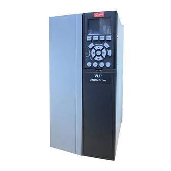
- Page 1 MAKING MODERN LIVING POSSIBLE Operating Instructions ® Compressor Drives CDS 302/CDS 303 www.DanfossDrives.com...
-
Page 3: Table Of Contents
3.3.4 Mains connection for B4, C1 and C3 3.3.5 Motor Compressor Connection 3.3.6 Motor Compressors Cables 3.3.7 Electrical Installation of Motor Compressor Cables 3.3.8 Compressor Motor Protection 3.3.9 Access to Control Terminals MG34M422 Danfoss A/S © Rev. 2013-07-03 All rights reserved. -
Page 4: Table Of Contents
5.2.3 Local Control Keys 5.2.4 Quick Transfer of Parameter Settings 5.2.5 Data Storage in LCP 5.2.6 Initialization to Default Settings 5.2.7 Data Transfer from LCP to Frequency Converter 5.2.8 Parameter Selection 5.2.9 Changing Data Danfoss A/S © Rev. 2013-07-03 All rights reserved. MG34M422... -
Page 5: Table Of Contents
6.16.1 Conversion 7 Troubleshooting 7.1 Status Messages 7.1.1 Warnings/Alarm Messages 8 General Specifications 8.1.1 Mains Supply 3x200-240 V AC 8.1.2 Mains Supply 3x380-480 V AC 8.1.3 Mains Supply 3x525-600 V AC Index MG34M422 Danfoss A/S © Rev. 2013-07-03 All rights reserved. -
Page 6: Introduction
• Operational efficiency • Flexibility & best control accuracy • Innovative and reliable solution The frequency converter is 100% preset for speed open loop configuration with 0-10 V reference corresponding to Danfoss A/S © Rev. 2013-07-03 All rights reserved. MG34M422... -
Page 7: Sequence Of Operation
VSH170 needs an external crankcase heater (surface sump heater or belt type). • Low Pressure Switch An LP switch is mandatory with the frequency converter compressor in any type of application. MG34M422 Danfoss A/S © Rev. 2013-07-03 All rights reserved. -
Page 8: Safety Instructions And General Warnings
From software versions 2.4x (CDS 302) and 1.0x (CDS 303), the output frequency of the frequency converter is Installation in high altitudes: limited to 590 Hz. By altitudes above 2 km (6561 ft), contact Danfoss regarding PELV. 2.1.4 Software Version 2.1.2 Caution CDS 302 Operating Instructions Software version: 2.4x... -
Page 9: General Warning
RFI capacitors from the RFI filter to ground, use 14-50 RFI permanent magnet motors. 1 on the frequency converter. This procedure reduces the RFI performance to A2 level. MG34M422 Danfoss A/S © Rev. 2013-07-03 All rights reserved. -
Page 10: Terminal 37 Safe Torque Off Function
Occupational Safety and Health of the German Social used, ensure the requirements of ISO 12100-2 paragraph Accident Insurance), and data for manual calculation. The 5.3.2.5 are fulfilled. library is permanently completed and extended. Danfoss A/S © Rev. 2013-07-03 All rights reserved. MG34M422... - Page 11 (ISO 13849-1) or SIL 2 (EN safety device must be short circuit protected 62061). according to ISO 13849-2 table D.4 • When external forces influence the motor axis (for example, suspended loads), more measures are MG34M422 Danfoss A/S © Rev. 2013-07-03 All rights reserved.
- Page 12 After installation and before first operation, perform a commissioning test of the installation using Safe Torque directly if it is required to control multiple frequency converters from the same control line via one Safety Relay Danfoss A/S © Rev. 2013-07-03 All rights reserved. MG34M422...
- Page 13 Figure 2.6 STO Category 4 Example Safety relay Emergency stop Table 2.3 Legend to Figure 2.4 Frequency converter [Reset] key Safety relay Emergency stop Table 2.5 Legend to Figure 2.6 Figure 2.5 SS1 Example MG34M422 Danfoss A/S © Rev. 2013-07-03 All rights reserved.
- Page 14 24 V DC are applied to Terminal 37. No Reset signal is defined by EN 60204-1. Emergency-Off requires measures required. of electrical isolation, for example, by switching off mains via an additional contactor. Danfoss A/S © Rev. 2013-07-03 All rights reserved. MG34M422...
-
Page 15: Safe Torque Off Commissioning Test
Safe Torque Off state, and the mechanical brake (if connected) remains activated. 1.3 Reapply 24 V DC to terminal 37. The test step is passed if the motor remains in the coasted MG34M422 Danfoss A/S © Rev. 2013-07-03 All rights reserved. -
Page 16: How To Install
113 °F to 131 °F, derating becomes relevant. If derating for Figure 3.3 Enclosure B4, IP20/Chassis ambient temperature is not taken into account, the service life of the unit is reduced. Danfoss A/S © Rev. 2013-07-03 All rights reserved. MG34M422... -
Page 17: Mechanical Mounting
The back wall must always be solid. All frequency converters are equipped with a back metal plate to guarantee proper heat exchanger ventilation. Never remove this metal sheet. MG34M422 Danfoss A/S © Rev. 2013-07-03 All rights reserved. -
Page 18: Mechanical Dimensions
Ø 0.75/19.0 Ø 0.35/9 Ø 0.35/9 0.34/8.8 0.33/8.5 Ø 0.35/9 0.33/8.5 0.35/9 0.35/9 0.31/7.9 0.59/15 0.38/9.8 0.67/17 Other Specifications Max. weight [lbs/kg] 50.4/23 59.53/27 26.46/12 51.81/23.5 99.21/45 77.16/35 Table 3.5 Mechanical Dimensions Danfoss A/S © Rev. 2013-07-03 All rights reserved. MG34M422... -
Page 19: Electrical Installation
Support cable entry around the knockout that should be removed • The knockout can now be removed with a strong mandrel and a hammer • Remove burrs from the hole • Mount cable entry on frequency converter MG34M422 Danfoss A/S © Rev. 2013-07-03 All rights reserved. -
Page 20: Mains Connection For B1, B2 And B3
93 labeled L1, L2, L3. Figure 3.7 How to Connect to Mains and Grounding for B1 and B2 Figure 3.8 How to Connect to Mains and Grounding for B3 without RFI Danfoss A/S © Rev. 2013-07-03 All rights reserved. MG34M422... - Page 21 Figure 3.10 How to Connect to Mains and Grounding for B4 Figure 3.11 How to Connect to Mains and Grounding for C1 and C2 Figure 3.12 How to Connect C3 to Mains and Grounding MG34M422 Danfoss A/S © Rev. 2013-07-03 All rights reserved.
-
Page 22: Motor Compressor Connection
Connect U, V, W for motor compressor clockwise. compressor • Make the screen connections with the largest possible surface area (cable clamp). Use the supplied installation devices in the frequency converter for making the screen connections. Danfoss A/S © Rev. 2013-07-03 All rights reserved. MG34M422... -
Page 23: Electrical Installation Of Motor Compressor Cables
If a compressor motor phase is missing, the of the removable cover shows the terminals. frequency converter trips • The frequency converter is protected against ground faults on compressor motor terminals T1, T2, T3 MG34M422 Danfoss A/S © Rev. 2013-07-03 All rights reserved. -
Page 24: Basic Wiring Example
3.3.10 Basic Wiring Example Mount terminals from the accessory bag to the front of the frequency converter. Figure 3.22 Mounting the Terminals Figure 3.19 Mounting the Cable Danfoss A/S © Rev. 2013-07-03 All rights reserved. MG34M422... - Page 25 How to Install Operating Instructions Connect terminals 18, 27 and 37 to +24 V (terminal 12/13) Default settings: 18 = start 27 = coast inverse Figure 3.23 Example of Basic Wiring MG34M422 Danfoss A/S © Rev. 2013-07-03 All rights reserved.
-
Page 26: Electrical Installation, Control Cables
Figure 3.24 Electrical Diagram - Control Cables Control cables must be shielded/armored. To connect the screen to the frequency converter decoupling plate for control cables, use a clamp from the accessory bag. Danfoss A/S © Rev. 2013-07-03 All rights reserved. MG34M422... - Page 27 If long control cables are used, 50/60 Hz ground loops may occur. Solve this problem by connecting one end of the screen to ground via a 100 nF capacitor (keeping leads short). MG34M422 Danfoss A/S © Rev. 2013-07-03 All rights reserved.
-
Page 28: Electrical Installation - Emc Protection
The EMC performance of flexible conduits varies a requirements are fulfilled. lot and information from the manufacturer must be obtained. Danfoss A/S © Rev. 2013-07-03 All rights reserved. MG34M422... - Page 29 How to Install Operating Instructions Figure 3.27 EMC Correct Installation of an IP20 Frequency Converter MG34M422 Danfoss A/S © Rev. 2013-07-03 All rights reserved.
-
Page 30: Safety Ground Connection
Controls using an external controller with 4-20 mA signal. Change switch 53 from U to I. It is not necessary to change any parameters, as this is the default value. Figure 3.29 Example of External Controller with 4-20 mA Signal Danfoss A/S © Rev. 2013-07-03 All rights reserved. MG34M422... -
Page 31: High-Voltage Test
The recommendations given do not provide UL branch circuit protection. Danfoss recommends using the fuses/circuit breakers listed in the following tables to protect service personnel and property in case of component break-down in the frequency converter. MG34M422 Danfoss A/S © Rev. 2013-07-03 All rights reserved. -
Page 32: Ce Compliance
3.4.3 CE Compliance Fuses or circuit breakers are mandatory to comply with IEC 60364. Danfoss recommends using a selection of the following. The fuses below are suitable for use on a circuit capable of delivering 100,000 Arms (symmetrical), 240 V, 480 V, 500 V, or 600 V depending on the unit's voltage rating. - Page 33 UL Compliance Fuses or circuit breakers are mandatory to comply with NEC 2009. Danfoss recommends using a selection of the following. The fuses below are suitable for use on a circuit capable of delivering 100,000 Arms (symmetrical), 240 V, 480 V, 500 V, or 600 V depending on the unit's voltage rating.
- Page 34 A6K-50-R 5014006-063 KLS-R-60 A6K-60-R 2028220-100 KLS-R-80 A6K-80-R 2028220-125 KLS-R-100 A6K-100-R 2028220-125 KLS-R-125 A6K-125-R 2028220-160 KLS-R-150 A6K-150-R 2028220-200 KLS-R-200 A6K-200-R 2028220-250 KLS-R-250 A6K-250-R Table 3.14 380-500 V, Frame Sizes B and C Danfoss A/S © Rev. 2013-07-03 All rights reserved. MG34M422...
- Page 35 Table 3.17 525-600 V, Frame Sizes B and C 170M fuses shown from Bussmann use the -/80 visual indicator. –TN/80 Type T, -/110 or TN/110 Type T indicator fuses of the same size and amperage may be substituted. MG34M422 Danfoss A/S © Rev. 2013-07-03 All rights reserved.
-
Page 36: Application Example
® How to Install Compressor Drives CDS 302/CDS 303 3.5 Application Example 3.5.1 BASIC Cascade/Pack Controller Figure 3.30 Example of BASIC Cascade/Pack Controller Danfoss A/S © Rev. 2013-07-03 All rights reserved. MG34M422... -
Page 37: System Status And Operation
LCP. Information displayed includes: • Compressor Status, is a readout of the status for the relays assigned to each compressor. The display shows compressors that are disabled, off, MG34M422 Danfoss A/S © Rev. 2013-07-03 All rights reserved. - Page 38 ® How to Install Compressor Drives CDS 302/CDS 303 Power card Figure 3.32 Example with Built-in BASIC Cascade Controller Danfoss A/S © Rev. 2013-07-03 All rights reserved. MG34M422...
-
Page 39: Quick Set-Up
See chapter 3.3.14 Basic Examples of Control then to “Basic PID Settings) menu. Connections. Now change parameters to Check if switch A53 is positioned to U (voltage) instead of I (current). The switch A53 is on the MG34M422 Danfoss A/S © Rev. 2013-07-03 All rights reserved. - Page 40 Ready to Run: Press [Auto On]. LCP. Select [1] Remote if the setpoint is given by For more details on PID Closed Loop, see Figure 4.4. Figure 4.4 Example of Closed Loop Application Danfoss A/S © Rev. 2013-07-03 All rights reserved. MG34M422...
-
Page 41: Other Compressor Features
Quick Set-up Operating Instructions 4.1.4 Other Compressor Features To set up other dedicated compressor features press [Quick Menu] and go to Q4 or follow Figure 4.5. Figure 4.5 Flowchart MG34M422 Danfoss A/S © Rev. 2013-07-03 All rights reserved. -
Page 42: How To Program
Status line: Status messages displaying text. 5.1.3 Display Contrast Adjustment ▼ Press [Status] and [ ] for darker display ▲ Press [Status] and [ ] for brighter display Danfoss A/S © Rev. 2013-07-03 All rights reserved. MG34M422... -
Page 43: Indicator Lights
Press [Status] to select the display mode or to change back to Display mode from either Quick Menu mode, Main Menu mode or Alarm mode. Also press [Status] to toggle single or double read-out mode. MG34M422 Danfoss A/S © Rev. 2013-07-03 All rights reserved. -
Page 44: Quick Transfer Of Parameter Settings
8-33 Parity / Stop Bits shortcut allows direct access to any parameter. • parameter 8-34 Estimated cycle time • parameter 8-35 Minimum Response Delay • parameter 8-36 Max Response Delay Danfoss A/S © Rev. 2013-07-03 All rights reserved. MG34M422... -
Page 45: Data Transfer From Lcp To Frequency Converter
5.2.7 Data Transfer from LCP to Frequency Converter NOTICE! Stop the motor compressor before performing this operation. Go to parameter 0-50 LCP Copy. Press [OK]. Select [2] All from LCP. Press [OK] again. MG34M422 Danfoss A/S © Rev. 2013-07-03 All rights reserved. -
Page 46: Parameter Selection
After selecting a parameter group, select a parameter with the navigation keys. The middle section on the display shows the parameter number and name as well as the selected parameter value. Figure 5.5 Display Example - Parameter Selection Danfoss A/S © Rev. 2013-07-03 All rights reserved. MG34M422... -
Page 47: Changing Data
▼ data value. [ ] increases the data value, and [ ] decreases the data value. Place the cursor on the value and press [OK] to save. Figure 5.6 Display Example MG34M422 Danfoss A/S © Rev. 2013-07-03 All rights reserved. -
Page 48: Parameter Descriptions
4-18 Current Limit parameter 28-42 DC Braking Time 1-44 d-axis Inductance (Ld) 200% I parameter 4-19 Max Output Frequency parameter 28-43 DC Brake Cut In Speed [RPM] Table 6.1 Compressor Related Parameters Danfoss A/S © Rev. 2013-07-03 All rights reserved. MG34M422... -
Page 49: Par. Group 0 - Operation And Display
LCP, FC ref=0 the frequency converter. RS-485, FC USB or up to five fieldbus sites. 0-10 Active Set-up Option: Function: Select the set-up to control the frequency converter functions. MG34M422 Danfoss A/S © Rev. 2013-07-03 All rights reserved. - Page 50 1 first, then ensure that Set-up 1 and Set-up 2 are synchronized (or ‘linked’). synchronization can be performed in two ways: 1. Change the edit set-up to [2] Set-up 2 in parameter 0-11 Edit Set-up and set Danfoss A/S © Rev. 2013-07-03 All rights reserved. MG34M422...
- Page 51 [1005] Readout Transmit Error Counter [1669] Pulse Output #27 [Hz] [1006] Readout Receive Error Counter [1670] Pulse Output #29 [Hz] [1007] Readout Bus Off Counter [1671] Relay Output [bin] [1013] Warning Parameter [1672] Counter A MG34M422 Danfoss A/S © Rev. 2013-07-03 All rights reserved.
- Page 52 [121] gal / sec. Option: Function: [122] gal/min Options are the same as in [123] gal / hr. parameter 0-20 Display Line 1.1 Small. [124] CFM [1613] Frequency [Hz] [125] ft³/s Danfoss A/S © Rev. 2013-07-03 All rights reserved. MG34M422...
- Page 53 If parameter 0-40 [Hand on] Key on LCP is included up over to each of the set-ups 1 to 4. in the Quick Menu, then define the password in parameter 0-65 Quick Menu Password. MG34M422 Danfoss A/S © Rev. 2013-07-03 All rights reserved.
- Page 54 Full access Disables the password defined in parameter 0-65 Quick Menu Password. Read only Prevents unauthorized editing of Quick Menu parameters. No access Prevents unauthorized viewing and editing of Quick Menu parameters. Danfoss A/S © Rev. 2013-07-03 All rights reserved. MG34M422...
-
Page 55: Par. Group 1 - Load And Motor
NOTICE! If the compressor selection is changed, then all dependent parameters reset to default and any user settings will be lost. Size [] Select the compressor/refrigerant combination dependent. for the system. MG34M422 Danfoss A/S © Rev. 2013-07-03 All rights reserved. -
Page 56: Par. Group 3 - Reference/Ramps
Define a fixed value (in %) to be added to 100.00 %] the variable value (defined in 3-18 Relative Scaling Reference Source). The sum of the fixed and variable values is multiplied with the actual reference. This product is then Danfoss A/S © Rev. 2013-07-03 All rights reserved. MG34M422... - Page 57 Resource 1. 3-41 Ramp Up Time Running (sec) function Range: Function: 5 s min. [Comp Enter the ramp-up time, i.e. the dependent] acceleration time to reach the system required motor speed. MG34M422 Danfoss A/S © Rev. 2013-07-03 All rights reserved.
- Page 58 4-18 Current Limit. The value 0.00 parameter 4-18 Current Limit. The value 0.00 Danfoss A/S © Rev. 2013-07-03 All rights reserved. MG34M422...
- Page 59 4-18 Current Limit). Quick-stop is motor, and such that the generated current activated by means of a signal on a does not exceed the current limit set in MG34M422 Danfoss A/S © Rev. 2013-07-03 All rights reserved.
- Page 60 P 4-13 RPM high limit Reference P 1-25 Motor speed P 4-11 RPM low limit Time P 3-81 Qramp Qstop Figure 6.5 Quick Stop Ramp Time Danfoss A/S © Rev. 2013-07-03 All rights reserved. MG34M422...
-
Page 61: Parameters: 4-** Limits/Warnings
01 or 02. Refer to parameter 1-00 Configuration Mode is in Figure 6.6. Torque Mode. No function Analog input 53 Analog input 53 MG34M422 Danfoss A/S © Rev. 2013-07-03 All rights reserved. - Page 62 27 or 29 4-13 RPM] certain output speeds due to and on relay output 01 or 02. resonance problems in the system. Enter the lower limits of the speeds to be avoided. Danfoss A/S © Rev. 2013-07-03 All rights reserved. MG34M422...
- Page 63 [ 0 - par. Some systems call for avoiding 4-14 Hz] certain output speeds due to resonance problems in the system. Enter the upper limits of the speeds to be avoided. MG34M422 Danfoss A/S © Rev. 2013-07-03 All rights reserved.
-
Page 64: Par. Group 5 - Digital In/Out
[19] Freeze output [20] Speed up [21] Speed down [22] Set-up select bit 0 [23] Set-up select bit 1 [24] Catch up [28] Slow down [29] Pulse input [32] 29, 33 Danfoss A/S © Rev. 2013-07-03 All rights reserved. MG34M422... - Page 65 (Default Digital input 19). Change the direction the value in parameter 2-02 DC Braking Time is of motor shaft rotation. Select Logic ‘1’ to different from 0. Logic ’0’ ⇒ DC braking. MG34M422 Danfoss A/S © Rev. 2013-07-03 All rights reserved.
- Page 66 Speed up and Speed down to be used. If Speed up/down is used, the speed change always follows ramp 2 (parameter 3-51 Ramp 2 Ramp Up Time and Danfoss A/S © Rev. 2013-07-03 All rights reserved. MG34M422...
- Page 67 [130] Compressor Use with cascade controller. Logic 1 will 5-19 Terminal 37 Safe Stop Interlock stop the fixed speed compressor and give Option: Function: a warning Safe Stop Alarm Safe Stop Warning MG34M422 Danfoss A/S © Rev. 2013-07-03 All rights reserved.
- Page 68 Run on The motor runs at reference speed. [30] Brake fault The output is Logic ‘1’ when the brake reference / no (IGBT) IGBT is short-circuited. Use this function to warning Danfoss A/S © Rev. 2013-07-03 All rights reserved. MG34M422...
- Page 69 The input will go low whenever Comparator 4 is evaluated as TRUE, the the Smart Logic Action [36] Set dig. out. A output will go high. Otherwise, it will be low is executed. low. MG34M422 Danfoss A/S © Rev. 2013-07-03 All rights reserved.
- Page 70 The bypass [13] Below Current, low valve control principle: [14] Above Current, high [15] Out of Speed Range [16] Below Speed, low [17] Above Speed, high [18] Out of Feedb. Range Danfoss A/S © Rev. 2013-07-03 All rights reserved. MG34M422...
- Page 71 [212] Cascade Compressor 2 there is a lot of noise in the system. A high [213] Cascade Compressor 3 time constant value results in better MG34M422 Danfoss A/S © Rev. 2013-07-03 All rights reserved.
- Page 72 5-60 Terminal 27 Pulse Output Variable Range: Function: Option: Function: 5000 Hz [0 - 32000 Hz] No operation Select the desired display output for terminal 27. [45] Bus ctrl. [48] Bus ctrl., timeout [51] MCO controlled Danfoss A/S © Rev. 2013-07-03 All rights reserved. MG34M422...
- Page 73 [0 - Set the output frequency transferred to the 100 %] output terminal 29 when the terminal is configured as [45] Bus Controlled in parameter 5-63 Terminal 29 Pulse Output Variable. MG34M422 Danfoss A/S © Rev. 2013-07-03 All rights reserved.
- Page 74 Parameter 8-04 Control Word Timeout Function Size [Enter the analog input scaling value related that corresponds to the low voltage/low Freeze Frozen at the present value current set in parameter 6-10 Terminal 53 Output Danfoss A/S © Rev. 2013-07-03 All rights reserved. MG34M422...
- Page 75 0-20 mA correspond to the maximum output [101] Reference parameter 3-00 Reference Range [Min - Max] value of the pressure sensor. 0-20 mA 0% = 0 mA; 100% = 20 mA MG34M422 Danfoss A/S © Rev. 2013-07-03 All rights reserved.
- Page 76 Analog output at zero torque = 12 mA. [107] Speed Taken from parameter 3-03 Maximum lim 4-20mA Motoric torque will increase the output Reference. 20 mA = value in parameter 3-03 Maximum Reference Danfoss A/S © Rev. 2013-07-03 All rights reserved. MG34M422...
- Page 77 4-20mA t.o. defines the behavior of the analog output in case of bus time-out. [150] Max Out Fr 0 Hz = 0 mA,parameter 4-19 Max Output 4-20mA Frequency = 20 mA. MG34M422 Danfoss A/S © Rev. 2013-07-03 All rights reserved.
-
Page 78: Par. Group 7 - Controllers
The filter time in flux sensorless must be adjusted to 3-5 ms. t (Sec.) Figure 6.10 Feedback Signal 6.8.1 7-2* Process PID Feedback Select the feedback sources for the Process PID Control, and how this feedback should be handled. Danfoss A/S © Rev. 2013-07-03 All rights reserved. MG34M422... - Page 79 Limit the DG to obtain a pure On Continue regulation of an error even when the output differentiator gain at slow changes and a constant frequency cannot be increased or decreased. differentiator gain where fast changes occur. MG34M422 Danfoss A/S © Rev. 2013-07-03 All rights reserved.
- Page 80 7-70 [173] ft WG Refrigerant. 7-61 Feedback 1 Source Unit Option: Function: Select the pressure unit applicable to feedback source 1 defined in 7-20 Process CL Feedback 1 Resource. Danfoss A/S © Rev. 2013-07-03 All rights reserved. MG34M422...
- Page 81 The Set-point should be set to a value in between Cut-in [-3000.00 – Selects the value used for the constant A2 and Cut-out. -1500.00] in the pressure to temperature conversion formula (see parameter group 7-7* Pressure to Temperature Conversion). MG34M422 Danfoss A/S © Rev. 2013-07-03 All rights reserved.
- Page 82 Function is inactive Function is active 7-81 Cut-out Value Range: Function: 1 bar [-3000 - par. Select the Cut-out Level where the 7-82] stop signal is activated and the compressor stops. Danfoss A/S © Rev. 2013-07-03 All rights reserved. MG34M422...
-
Page 83: Parameters: 8-** Communications And Options
Select setup 2 See [7] Select setup 1 Option B Select setup 3 See [7] Select setup 1 Option C0 Option C1 [10] Select setup 4 See [7] Select setup 1 [30] External Can [26] Trip MG34M422 Danfoss A/S © Rev. 2013-07-03 All rights reserved. - Page 84 For additional guidelines in the selection of [1] PROFIdrive profile, No Parity, 1 Stop Bit refer to the Operating Instructions for the installed fieldbus. No Parity, 2 Stop Bits Option: Function: FC profile PROFIdrive profile Danfoss A/S © Rev. 2013-07-03 All rights reserved. MG34M422...
- Page 85 Activates Start command via the fieldbus/serial [3] Logic OR Activates the Reverse command via the fieldbus/ communication port OR via one of the digital serial communication port OR via one of the inputs. digital inputs. MG34M422 Danfoss A/S © Rev. 2013-07-03 All rights reserved.
- Page 86 8-81 Bus Error Count Range: Function: [0 - 0 ] This parameter shows the number of telegrams with faults (e.g. CRC fault), detected on the bus. Danfoss A/S © Rev. 2013-07-03 All rights reserved. MG34M422...
-
Page 87: Par. Group 13 - Smart Logic Control
[0] (and only event [0]) each scan interval. Only when event [0] is evaluated TRUE, will the SLC execute action [0] and start evaluating event [1]. It is possible to programme from 1 to 20 events and actions. MG34M422 Danfoss A/S © Rev. 2013-07-03 All rights reserved. - Page 88 4-57 Warning Feedback High. [45] Left key [◄] is pressed. [16] Thermal The thermal warning turns on when the warning temperature exceeds the limit in the [46] Right key [►] is pressed. Danfoss A/S © Rev. 2013-07-03 All rights reserved. MG34M422...
- Page 89 Mains out of range [76] Digital input x30/2 [18] Reverse [77] Digital input x30/3 [19] Warning [78] Digital input x30/4 [20] Alarm (trip) [79] Digital input x46/1 [21] Alarm (trip lock) MG34M422 Danfoss A/S © Rev. 2013-07-03 All rights reserved.
- Page 90 Comparators which they are set to TRUE or FALSE, [100] RS Flipflop 6 See parameter group 13-1* respectively. See Comparators parameter 13-11 Comparator Operator. Danfoss A/S © Rev. 2013-07-03 All rights reserved. MG34M422...
- Page 91 TRUE Enters the fixed value of true in the range parameter 4-56 Warning Feedback Low and comparator. parameter 4-57 Warning Feedback High. [52] Control ready The control board receives supply voltage MG34M422 Danfoss A/S © Rev. 2013-07-03 All rights reserved.
- Page 92 [185] Drive in hand High when the frequency converter is in mode hand mode. [122] SL Timeout 2 The result of SLC timer 2. [123] SL Timeout 3 The result of SLC timer 3. Danfoss A/S © Rev. 2013-07-03 All rights reserved. MG34M422...
- Page 93 The following settings can be used to [5] TRUE set up the same digital input as start/stop (example given longer with DI32 but is not a requirement). than... MG34M422 Danfoss A/S © Rev. 2013-07-03 All rights reserved.
- Page 94 Digital input x30/2 [10] Out of speed range [77] Digital input x30/3 [11] Below speed low [78] Digital input x30/4 [12] Above speed high [79] Digital input x46/1 [13] Out of feedb. range Danfoss A/S © Rev. 2013-07-03 All rights reserved. MG34M422...
- Page 95 [25] Comparator 3 [96] RS Flipflop 2 [26] Logic rule 0 [97] RS Flipflop 3 [27] Logic rule 1 [98] RS Flipflop 4 [28] Logic rule 2 [99] RS Flipflop 5 MG34M422 Danfoss A/S © Rev. 2013-07-03 All rights reserved.
- Page 96 Logic Rule Boolean 3 [30] SL Timeout 0 Figure 6.18 Logic Rules [31] SL Timeout 1 [32] SL Timeout 2 [33] Digital input DI18 Priority of calculation [34] Digital input DI19 Danfoss A/S © Rev. 2013-07-03 All rights reserved. MG34M422...
- Page 97 [13-42]. will be 1. [7] NOT AND Evaluates the expression NOT [13-40] AND [92] ATEX ETR freq. warning Selectable if parameter 1-90 Motor NOT [13-42]. Thermal Protection is set to [20] MG34M422 Danfoss A/S © Rev. 2013-07-03 All rights reserved.
- Page 98 ATEX ETR freq. warning Selectable if parameter 1-90 Motor [33] Digital input DI18 Thermal Protection is set to [20] [34] Digital input DI19 ATEX ETR or [21] Advanced ETR. If [35] Digital input DI27 Danfoss A/S © Rev. 2013-07-03 All rights reserved. MG34M422...
- Page 99 Digital input DI33 [4] OR NOT [39] Start command [5] NOT AND [40] Drive stopped [6] NOT OR [41] Reset Trip [7] NOT AND NOT [42] Auto-reset Trip [8] NOT OR NOT MG34M422 Danfoss A/S © Rev. 2013-07-03 All rights reserved.
- Page 100 Selectable if parameter 1-90 Motor [19] Warning Thermal Protection is set to [20] [20] Alarm (trip) ATEX ETR or [21] Advanced ETR]. If [21] Alarm (trip lock) the warning 165 ATEX ETR Danfoss A/S © Rev. 2013-07-03 All rights reserved. MG34M422...
- Page 101 Digital input x46/5 evaluated as true. The following actions are [82] Digital input x46/7 available for selection: [83] Digital input x46/9 [0] *DISABLED [84] Digital input x46/11 No action [85] Digital input x46/13 MG34M422 Danfoss A/S © Rev. 2013-07-03 All rights reserved.
- Page 102 A low inputs or via a fieldbus. [33] Set digital out Any output with SL output B will be low. [15] Select preset Selects preset reference 5. B low ref 5 Danfoss A/S © Rev. 2013-07-03 All rights reserved. MG34M422...
- Page 103 [73] Start timer 6 Start Timer 6, see parameter 13-20 SL Controller Timer for further description. [74] Start timer 7 Start Timer 7, see parameter 13-20 SL Controller Timer for further description. MG34M422 Danfoss A/S © Rev. 2013-07-03 All rights reserved.
- Page 104 Select Control card test [1]. [10] Automatic reset Performs between one and twenty Disconnect the mains supply and wait x 10 automatic resets after tripping. for the light in the display to go out. Danfoss A/S © Rev. 2013-07-03 All rights reserved. MG34M422...
- Page 105 Derate Reduce pump speed to decrease the load on the initiali- Resets all parameter values to default settings, power section and allowing this to cool down. zation except for parameter 15-03 Power Up's, parameter 15-04 Over Temp's and MG34M422 Danfoss A/S © Rev. 2013-07-03 All rights reserved.
- Page 106 Table 6.10 Table for Selection of Choice of Action when Selected Alarm Appears D = Default setting. x = possible selection. 1) Only high power drives In FC small and medium A69 is only a warning Danfoss A/S © Rev. 2013-07-03 All rights reserved. MG34M422...
- Page 107 [0 - 65535 ] View the number of frequency converter temperature faults which have occurred. 15-05 Over Volts Range: Function: [0 - 65535 ] View the number of frequency converter overvoltages which have occurred. MG34M422 Danfoss A/S © Rev. 2013-07-03 All rights reserved.
-
Page 108: Parameters: 16-** Data Readouts
(scale 0000-4000 Max Value Hex) of parameter 4-19 Max Output Frequency. Set parameter 9-16 PCD Read Configuration index 1 to send it with the status word instead of the MAV. Danfoss A/S © Rev. 2013-07-03 All rights reserved. MG34M422... - Page 109 [-200 - 200 %] Value shown is the torque in percent of data are used for calculation of nominal torque, with sign, applied to the torque, motor protection, etc. motor shaft. MG34M422 Danfoss A/S © Rev. 2013-07-03 All rights reserved.
- Page 110 16-51 Pulse Reference Range: Function: [-200 - 200 ] View the reference value from programmed digital input(s). The readout can also reflect the impulses from an incremental encoder. Danfoss A/S © Rev. 2013-07-03 All rights reserved. MG34M422...
- Page 111 [-20 - 20 ] View the actual value at input 53. 16-63 Terminal 54 Switch Setting Figure 6.23 Relay Settings Option: Function: View the setting of input terminal 54. Current Voltage MG34M422 Danfoss A/S © Rev. 2013-07-03 All rights reserved.
- Page 112 For more information, refer to the relevant 16-93 Warning Word 2 fieldbus manual. Range: Function: [0 - 4294967295 ] View the warning word sent via the serial communication port in hex code. Danfoss A/S © Rev. 2013-07-03 All rights reserved. MG34M422...
- Page 113 16-95 Ext. Status Word 2 Range: Function: [0 - 4294967295 ] Returns the extended warning word 2 sent via the serial communication port in hex code. MG34M422 Danfoss A/S © Rev. 2013-07-03 All rights reserved.
-
Page 114: Par. Group 25 - Cascade Controller
Figure 6.24 Cascade Controller Feedback Signals Figure 6.25 Configuring the Cascade Controller Danfoss A/S © Rev. 2013-07-03 All rights reserved. MG34M422... - Page 115 25-05 Fixed Lead Compressor. Two fixed speed the order 1 – 2 – 3 and disconnected in the order compressors controlled by built-in relays. 3 – 2 – 1. (First in – last out) MG34M422 Danfoss A/S © Rev. 2013-07-03 All rights reserved.
- Page 116 Cascade Controller must stop the system The OBW is a percentage of immediately by cutting out all the fixed speed parameter 3-03 Maximum Reference. compressors. This is basically the same as Danfoss A/S © Rev. 2013-07-03 All rights reserved. MG34M422...
- Page 117 Inverse Control is programmed to Inverse), with (27-20) at least one fixed speed compressor in the stop position. When the programmed value of the timer expires, a fixed speed compressor is Figure 6.29 SBW Destaging Delay staged. MG34M422 Danfoss A/S © Rev. 2013-07-03 All rights reserved.
- Page 118 Figure 6.33 Staging Threshold speed compressor to eliminate pressure surges in the system. Only to be used if [1] Soft Starter is selected in parameter 25-02 Motor Start. Danfoss A/S © Rev. 2013-07-03 All rights reserved. MG34M422...
- Page 119 0 N/A Readout of the below calculated value for Staging Speed When adding a fixed speed compressor, in order to prevent an overshoot of pressure, the variable speed compressor ramps down to a lower MG34M422 Danfoss A/S © Rev. 2013-07-03 All rights reserved.
- Page 120 See For the Basic Cascade Controller all compressors parameter 25-51 Alternation Event for available are equal size. options. Disabled [0]: The lead compressor alternation will take place at any compressor capacity. Danfoss A/S © Rev. 2013-07-03 All rights reserved. MG34M422...
- Page 121 Alternation, is different from [0] Off. This parameter sets the time between stopping the old variable speed compressor and starting this compressor as a new fixed speed compressor. Refer to parameter 25-56 Staging Mode at MG34M422 Danfoss A/S © Rev. 2013-07-03 All rights reserved.
- Page 122 0 by writing in the compressors showing a string, which consists of parameter, e.g. if the compressor is replaced in case of service. Danfoss A/S © Rev. 2013-07-03 All rights reserved. MG34M422...
- Page 123 25-50 Lead Compressor Alternation. The parameter is for manually setting of what compressor to be assigned as variable speed compressor. The default value of Manual Alternation is [0] Off. If a value other MG34M422 Danfoss A/S © Rev. 2013-07-03 All rights reserved.
- Page 124 An oil return boost is performed at fixed time 168 h] intervals to complement the oil return boosts triggered by inadequate flow speeds (parameter 28-11 Low Speed Running Time). The fixed interval boosts ensure that oil return boosts Danfoss A/S © Rev. 2013-07-03 All rights reserved. MG34M422...
- Page 125 Ref./Feedb. Value to match the characteristics of monitored without affecting drive operations. the device. Analog The measurement device is connected to input input 54 terminal 54. Program parameter 6-20 Terminal 54 MG34M422 Danfoss A/S © Rev. 2013-07-03 All rights reserved.
- Page 126 Selects the temperature at [parameter 28-24 Warning which an alarm shall be issued. Level-300] Enter the temperature in the unit programmed in parameter 28-21 Temperature Unit. Danfoss A/S © Rev. 2013-07-03 All rights reserved. MG34M422...
- Page 127 (parameter 4-14 Motor Speed High Limit [Hz]) to match 0%, Option: Function: 25%, 50%, 75% and 100% loads as good as possible. The Do not reset No function Reset Clears the measured running time in all five speed intervals. MG34M422 Danfoss A/S © Rev. 2013-07-03 All rights reserved.
- Page 128 28-74 Night Speed Drop [RPM] Range: Function: The value in this parameter decrements the value in parameter 4-13 Motor Speed High Limit [RPM] which becomes active when night mode is activated. Danfoss A/S © Rev. 2013-07-03 All rights reserved. MG34M422...
-
Page 129: Parameter Lists
0.1. The value 100 is therefore read as 10.0. Examples: 0s ⇒ conversion index 0 0.00s ⇒ conversion index -2 0ms ⇒ conversion index -3 0.00ms ⇒ conversion index -5 MG34M422 Danfoss A/S © Rev. 2013-07-03 All rights reserved. - Page 130 Date Format ExpressionLimit 1 set-up TRUE Uint8 0-72 Time Format ExpressionLimit 1 set-up TRUE Uint8 0-74 DST/Summertime [0] Off 1 set-up TRUE Uint8 0-76 DST/Summertime Start ExpressionLimit 1 set-up TRUE TimeOfDay Danfoss A/S © Rev. 2013-07-03 All rights reserved. MG34M422...
- Page 131 TRUE Uint8 0-82 Additional Working Days ExpressionLimit 1 set-up TRUE TimeOfDay 0-83 Additional Non-Working Days ExpressionLimit 1 set-up TRUE TimeOfDay 0-89 Date and Time Readout 0 N/A All set-ups TRUE VisStr[25] MG34M422 Danfoss A/S © Rev. 2013-07-03 All rights reserved.
- Page 132 Uint8 1-7* Start Adjustments 1-70 PM Start Mode [1] Parking All set-ups TRUE Uint8 1-71 Start Delay 00 s All set-ups TRUE Uint16 1-72 Start Function ExpressionLimit All set-ups TRUE Uint8 Danfoss A/S © Rev. 2013-07-03 All rights reserved. MG34M422...
- Page 133 1-9* Motor Temperature 1-90 Motor Thermal Protection ExpressionLimit All set-ups TRUE Uint8 1-91 Motor External Fan [0] None All set-ups TRUE Uint8 1-93 Thermistor Source [0] None All set-ups TRUE Uint8 MG34M422 Danfoss A/S © Rev. 2013-07-03 All rights reserved.
- Page 134 [0] Off All set-ups TRUE Uint8 3-93 Maximum Limit 100 % All set-ups TRUE Int16 3-94 Minimum Limit All set-ups TRUE Int16 3-95 Ramp Delay 1 N/A All set-ups TRUE TimD Danfoss A/S © Rev. 2013-07-03 All rights reserved. MG34M422...
- Page 135 Uint16 4-62 Bypass Speed To [RPM] ExpressionLimit All set-ups TRUE Uint16 4-63 Bypass Speed To [Hz] ExpressionLimit All set-ups TRUE Uint16 4-64 Semi-Auto Bypass Set-up [0] Off All set-ups FALSE Uint8 MG34M422 Danfoss A/S © Rev. 2013-07-03 All rights reserved.
- Page 136 5-90 Digital & Relay Bus Control 0 N/A All set-ups TRUE Uint32 5-93 Pulse Out #27 Bus Control All set-ups TRUE 5-94 Pulse Out #27 Timeout Preset 1 set-up TRUE Uint16 Danfoss A/S © Rev. 2013-07-03 All rights reserved. MG34M422...
- Page 137 All set-ups TRUE 5-96 Pulse Out #29 Timeout Preset 1 set-up TRUE Uint16 5-97 Pulse Out #X30/6 Bus Control All set-ups TRUE 5-98 Pulse Out #X30/6 Timeout Preset 1 set-up TRUE Uint16 MG34M422 Danfoss A/S © Rev. 2013-07-03 All rights reserved.
- Page 138 6-60 Terminal X30/8 Output [0] No operation All set-ups TRUE Uint8 6-61 Terminal X30/8 Min. Scale All set-ups TRUE Int16 6-62 Terminal X30/8 Max. Scale 100 % All set-ups TRUE Int16 Danfoss A/S © Rev. 2013-07-03 All rights reserved. MG34M422...
- Page 139 Default value 4-set-up Change Conver- Type No. # during sion index operation 6-63 Terminal X30/8 Output Bus Control All set-ups TRUE 6-64 Terminal X30/8 Output Timeout Preset 1 set-up TRUE Uint16 MG34M422 Danfoss A/S © Rev. 2013-07-03 All rights reserved.
- Page 140 Uint16 7-36 Process PID Diff. Gain Limit 5.0 N/A All set-ups TRUE Uint16 7-38 Process PID Feed Forward Factor All set-ups TRUE Uint16 7-39 On Reference Bandwidth All set-ups TRUE Uint8 Danfoss A/S © Rev. 2013-07-03 All rights reserved. MG34M422...
- Page 141 0 N/A All set-ups TRUE Uint32 8-9* Bus Jog 8-90 Bus Jog 1 Speed 100 RPM All set-ups TRUE Uint16 8-91 Bus Jog 2 Speed 200 RPM All set-ups TRUE Uint16 MG34M422 Danfoss A/S © Rev. 2013-07-03 All rights reserved.
- Page 142 Function at Inverter Overload [1] Derate All set-ups TRUE Uint8 14-62 Inv. Overload Derate Current 95 % All set-ups TRUE Uint16 14-9* Fault Settings 14-90 Fault Level ExpressionLimit 1 set-up TRUE Uint8 Danfoss A/S © Rev. 2013-07-03 All rights reserved. MG34M422...
- Page 143 15-6* Option Ident 15-60 Option Mounted 0 N/A All set-ups FALSE VisStr[30] 15-61 Option SW Version 0 N/A All set-ups FALSE VisStr[20] 15-62 Option Ordering No 0 N/A All set-ups FALSE VisStr[8] MG34M422 Danfoss A/S © Rev. 2013-07-03 All rights reserved.
- Page 144 VisStr[20] 15-9* Parameter Info 15-92 Defined Parameters 0 N/A All set-ups FALSE Uint16 15-93 Modified Parameters 0 N/A All set-ups FALSE Uint16 15-99 Parameter Metadata 0 N/A All set-ups FALSE Uint16 Danfoss A/S © Rev. 2013-07-03 All rights reserved. MG34M422...
- Page 145 16-65 Analog Output 42 [mA] 0 N/A All set-ups FALSE Int16 16-66 Digital Output [bin] 0 N/A All set-ups FALSE Int16 16-67 Pulse Input #29 [Hz] 0 N/A All set-ups FALSE Int32 MG34M422 Danfoss A/S © Rev. 2013-07-03 All rights reserved.
- Page 146 Uint32 16-94 Ext. Status Word 0 N/A All set-ups FALSE Uint32 16-95 Ext. Status Word 2 0 N/A All set-ups FALSE Uint32 16-96 Maintenance Word 0 N/A All set-ups FALSE Uint32 Danfoss A/S © Rev. 2013-07-03 All rights reserved. MG34M422...
- Page 147 All set-ups TRUE Uint16 25-88 Pack capacity [%] All set-ups TRUE Uint16 25-9* Service 25-90 Compressor Interlock [0] Off All set-ups TRUE Uint8 25-91 Manual Alternation 0 N/A All set-ups TRUE Uint8 MG34M422 Danfoss A/S © Rev. 2013-07-03 All rights reserved.
- Page 148 Load Profile Data 0 N/A All set-ups TRUE Uint16 28-7* Day/Night Settings 28-74 Night Speed Drop [RPM] ExpressionLimit All set-ups TRUE Uint16 28-76 Night Speed Drop [Hz] ExpressionLimit All set-ups TRUE Uint16 Danfoss A/S © Rev. 2013-07-03 All rights reserved. MG34M422...
- Page 149 Parameter 14-12 Functi on at Mains Imbalance DC link voltage high DC link voltage low DC over-voltage DC under voltage Inverter overloaded Motor ETR over temperature Parameter 1-90 Motor Thermal Protection MG34M422 Danfoss A/S © Rev. 2013-07-03 All rights reserved.
- Page 150 5-02 Termina l 29 Mode Ovrld X30/6-7 Ext. Supply (option) Ground Fault 2 Pwr. card supply 24 V supply low 1.8 V supply low Speed limit parameter 1-86 Trip Speed Low [RPM] Danfoss A/S © Rev. 2013-07-03 All rights reserved. MG34M422...
- Page 151 Illegal Option Combination No Safety Option Dang fail PB Dang fail DI Option Detection Mechanical Brake Sliding Feedback Monitor Parameter 17-61 Feedb ack Signal Monitoring Analog input 54 wrong settings S202 MG34M422 Danfoss A/S © Rev. 2013-07-03 All rights reserved.
- Page 152 ATEX ETR freq.lim.warning ATEX ETR freq.lim.alarm Pwr.card supply New spare parts New Type Code Table 7.1 Alarm/Warning Code List (X) Dependent on parameter 1) Cannot be Auto reset via parameter 14-20 Reset Mode Danfoss A/S © Rev. 2013-07-03 All rights reserved. MG34M422...
- Page 153 Quick Stop (A9) High High speed > 4-53 00000400 1024 DC under Volt Start Failed DC under Volt (W8) Multi- Output Freq Low DC Brake (A8) motor speed < 4-52 underloa MG34M422 Danfoss A/S © Rev. 2013-07-03 All rights reserved.
- Page 154 Drive Bypass (A36) 02000000 33554432 1.8V Supply Current Limit Current Limit (W59) reserved Unused Fire Mode Low (A48) (A59) 04000000 67108864 Brake Resistor reserved Low Temp (W66) reserved Unused External Interlock (A25) Danfoss A/S © Rev. 2013-07-03 All rights reserved. MG34M422...
- Page 155 Increase parameter 14-26 Trip Delay at Inverter No motor has been connected to the output of the Fault frequency converter. If the alarm/warning occurs during a power sag, use kinetic back-up (parameter 14-10 Line Failure) MG34M422 Danfoss A/S © Rev. 2013-07-03 All rights reserved.
- Page 156 The warning lasts about 1.5 s, then the adjustable frequency drive trips and issues an alarm. This fault can be caused by shock loading or quick acceleration with high inertia loads. It can also appear after Danfoss A/S © Rev. 2013-07-03 All rights reserved. MG34M422...
- Page 157 Word Timeout Function is NOT set to [0] Off. If parameter 8-04 Control Word Timeout Function is set to [5] Stop and Trip, a warning appears and the frequency converter ramps down until it stops then displays an alarm. MG34M422 Danfoss A/S © Rev. 2013-07-03 All rights reserved.
- Page 158 Cycle power Troubleshooting Check that the option is properly installed Check for the following conditions. Check for loose or missing wiring Ambient temperature too high. Motor cable too long. Danfoss A/S © Rev. 2013-07-03 All rights reserved. MG34M422...
- Page 159 Troubleshooting Operating Instructions It may be necessary to contact your Danfoss supplier or WARNING 41, Overload of digital output terminal 29 service department. Note the code number for further Check the load connected to terminal 29 or remove short- troubleshooting directions.
- Page 160 The temperature sensor on the power card is either too external fault condition. To resume normal operation, apply hot or too cold. 24 V DC to the terminal programmed for external interlock. Reset the frequency converter. Danfoss A/S © Rev. 2013-07-03 All rights reserved. MG34M422...
- Page 161 The hoist brake monitor has detected a motor speed > 10 Troubleshooting: RPM. When replacing an F-frame module, this warning occurs, if the power-specific data in the module power card does MG34M422 Danfoss A/S © Rev. 2013-07-03 All rights reserved.
- Page 162 3 = right inverter module in F2 or F4 frequency converter. 5 = rectifier module. WARNING 250, New spare part A component in the adjustable frequency drive has been replaced. Reset the adjustable frequency drive for normal operation. Danfoss A/S © Rev. 2013-07-03 All rights reserved. MG34M422...
- Page 163 Although measurements are made with state of the art equipment, some measurement inaccuracy must be allowed for ( 5) The three values for the max. cable cross section are for single core, flexible wire and flexible wire with sleeve, respectively. MG34M422 Danfoss A/S © Rev. 2013-07-03 All rights reserved.
- Page 164 Although measurements are made with state of the art equipment, some measurement inaccuracy must be allowed for ( 5) The three values for the max. cable cross section are for single core, flexible wire and flexible wire with sleeve, respectively. Danfoss A/S © Rev. 2013-07-03 All rights reserved. MG34M422...
- Page 165 [W] Weight, enclosure IP21, IP55, IP66 [lbs/kg] 50.4/23 59.5/27 59.5/27 Weight, enclosure IP20 [lbs/kg] 26.46/12 51.8/23.5 51.8/23.5 0.98 0.98 0.98 Efficiency Table 8.3 Mains Supply 3x525-600 V AC MG34M422 Danfoss A/S © Rev. 2013-07-03 All rights reserved.
- Page 166 All digital inputs are galvanically isolated from the supply voltage (PELV) and other high-voltage terminals. Terminals 27 and 29 can also be programmed as output. Except safe stop input Terminal 37. Terminal 37 can only be used as safe stop input. Danfoss A/S © Rev. 2013-07-03 All rights reserved. MG34M422...
- Page 167 Resolution of frequency outputs 12 bit Terminal 27 and 29 can also be programmed as input. The digital output is galvanically isolated from the supply voltage (PELV) and other high-voltage terminals. MG34M422 Danfoss A/S © Rev. 2013-07-03 All rights reserved.
- Page 168 Max. terminal load (AC-15)1) on 4-5 (NO) (Inductive load @ cosφ 0.4) 240 V AC, 0.2 A Max. terminal load (DC-1)1) on 4-5 (NO) (Resistive load) 80 V DC, 2 A Danfoss A/S © Rev. 2013-07-03 All rights reserved. MG34M422...
- Page 169 Derating for high altitude, see section on special conditions EMC standards, Emission EN 61800-3, EN 61000-6-3/4, EN 55011, IEC 61800-3 EN 61800-3, EN 61000-6-1/2, EMC standards, Immunity EN 61000-4-2, EN 61000-4-3, EN 61000-4-4, EN 61000-4-5, EN 61000-4-6 MG34M422 Danfoss A/S © Rev. 2013-07-03 All rights reserved.
- Page 170 Default Settings.................. 127 Mains connection for B4, C1 and C3..........1 Diagnosis Read-Outs, 16-9*............110 Mains supply..............7, 24, 42, 102 Digital input..........62, 102, 118, 121, 154, 166 Mains Supply................161, 164 Danfoss A/S © Rev. 2013-07-03 All rights reserved. MG34M422...
- Page 171 Screened/armored............... 20, 26, 164 Sequence of Operation................. 5 Shielded/armoured............... 24, 25 Short circuit..................155 Short Circuit Protection..............29 Speed Bypass, 4-6*................60 States, 13-5*.................... 98 Stripping....................22 Supply voltage..................156 Surroundings..................167 MG34M422 Danfoss A/S © Rev. 2013-07-03 All rights reserved.
- Page 172 Danfoss shall not be responsible for any errors in catalogs, brochures or other printed material. Danfoss reserves the right to alter its products at any time without notice, provided that alterations to products already on order shall not require material changes in specifications previously agreed upon by Danfoss and the Purchaser. All trademarks in this material are property of the respective companies.