Advertisement
Available languages
Available languages
Bedienungs‐ und Wartungsanleitung
Versenkregner mit integriertem Ventil
Maintenance and Operating Instructions
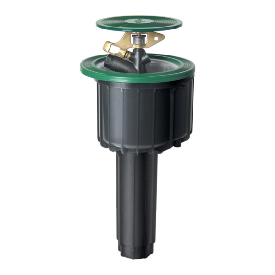
Pop‐up sprinkler with integrated valve
TDP021 d+e.doc
Perrot REGNERBAU CALW GmbH Industriestrasse 19‐29 / D‐75382 Althengstett / Germany
Phone: +49‐7051‐162‐0 / Fax : +49‐7051‐162–133
E‐mail :perrot@perrot.de / E‐mail Technical Department: technik@perrot.de
PERROT
PERROT
LVZR 22‐3 V
LVZR 22‐3 V AC/DC
LVZR 22‐3 VDE
Rev. 29.10.2013
Seite / Page 1 / 20
Advertisement

Related Manuals for Perrot VZR 22-3VDE


Summary of Contents for Perrot VZR 22-3VDE
- Page 1 Bedienungs‐ und Wartungsanleitung PERROT Versenkregner mit integriertem Ventil Maintenance and Operating Instructions PERROT Pop‐up sprinkler with integrated valve LVZR 22‐3 V LVZR 22‐3 V AC/DC LVZR 22‐3 VDE TDP021 d+e.doc Rev. 29.10.2013 Seite / Page 1 / 20 Perrot REGNERBAU CALW GmbH Industriestrasse 19‐29 / D‐75382 Althengstett / Germany Phone: +49‐7051‐162‐0 / Fax : +49‐7051‐162–133 E‐mail :perrot@perrot.de / E‐mail Technical Department: technik@perrot.de ...
-
Page 2: Table Of Contents
6. Wartung 7. Betriebsstörung und Behebung 1. Allgemeines Wir gehen davon aus, dass Sie sich auf dem Gebiet der Beregnung auskennen. Deshalb haben wir diese Anleitung kurzgefasst und nur diejenigen Informationen hineingebracht, die Sie im Hinblick auf die Verwendung dieses Produktes unbedingt erhalten müssen. Gewährleistung kann nur übernommen werden, wenn der Regner unter Beachtung dieser Betriebsanleitung betrieben wurde und innerhalb der Garantiezeit Mängel aufweist. 1.1. Verwendungszweck Der Regner wird zur gleichmäßigen Verteilung von Wasser eingesetzt. Das Wasser sollte vorgereinigt sein, frei von grober und langfasriger Verschmutzung. Max. Wassertemperatur beträgt 50°C. Max. Umgebungstemperatur beträgt 75°C. 2. Sicherheit Diese Betriebs‐ und Sicherheitsanleitung enthält grundlegende Hinweise, die bei Montage, Betrieb, Wartung und Instandsetzung zu beachten sind. Daher ist diese Betriebsanleitung unbedingt vor Montage und Inbetriebnahme vom Monteur sowie dem zuständigen Fachpersonal / Betreiber zu lesen. TDP021 d+e.doc Rev. 29.10.2013 Seite / Page 2 / 20 Perrot REGNERBAU CALW GmbH Industriestrasse 19‐29 / D‐75382 Althengstett / Germany Phone: +49‐7051‐162‐0 / Fax : +49‐7051‐162–133 E‐mail :perrot@perrot.de / E‐mail Technical Department: technik@perrot.de ... -
Page 3: Beschreibung
Empfohlener Betriebsdruck 5 bis 6 bar Zulässiger Betriebsdruck 3 bis 8 bar Der Druck am Regner darf 10bar nicht übersteigen Weitere Daten siehe separates Datenblatt 4. M ontage Vor Montage der Regner die Leitungen sorgfältig spülen Gewindeanschluss am Regner ist 1½“ IG Zur Gewindeabdichtung Teflonband Spezial verwenden. Einbau der Regner sollte gemäß „Einbauschema für Versenkregner PERROT LVZR 22 VAC“ erfolgen (siehe nächste Seite). Damit Auflastdrücke auf das Leitungsrohr vermieden werden, ist auf jeden Fall ein Regnergelenk zu verwenden. Der Einbau einer Sickerpackung, wie im Einbauschema gezeigt, wird dringend empfohlen. Die Verbindung der Steuerkabel darf nur mit zugelassenen wasserdichten Verbindungen ausgeführt werden. Aufschrauben des Regners auf das Regnergelenk durch Festhalten am Gehäuserand oder durch Einsatz eines Bandschlüssels. TDP021 d+e.doc ... - Page 4 Einbauschema für Versenkregner / Installation layout for pop‐up sprinkler PERROT LVZR 22 (W/V XX) PE‐Hauptleitung / dia Main Pipe Schema A Schema B Teile Nr. 63 75 90 63 75 90 Pos. Benennung Description Article No. T‐Stück 90° 63 x 1½“ IG T‐piece 90° 63 x 1½“ FT ZH90153 1 1 T‐Stück 90° 75 x 2½“ IG T‐piece 90° 75 x 2½“ FT ZH90157 1 T‐Stück 90° 90 x 3“ IG T‐piece 90° 90 x 3“ FT ZH90158 ...
-
Page 5: Inbetriebnahme / Winterfestmachung
Ventil und Regner auf einwandfreie Funktion prüfen, indem Ventil elektrisch angesteuert wird. e) Bei Sektorregner kann im Betrieb der gewünschte Beregnungssektor an den Sektoranschlägen [14] eingestellt werden. f) Nachdem der Regner vollständig entlüftet ist, kann Steuerstrom abgeschaltet werden. 5.1.3 R egner mit hydraulischem Ventil LVZR 22V Steuerleitungen zuerst befüllen und anschließend nacheinander vollständig entlüften. Die Entlüftungsschraube befindet sich im Regnergehäuse (siehe Bild 1). Schieber der Hauptleitung öffnen. 5.2 Winterfestmachung Vor Eintritt der Frostperiode, muss Regner entleert werden. Hierfür muss am Leitungsnetz ein leistungsstarker Kompressor angeschlossen werden. Ventil am Regner so lange geöffnet lassen, bis aus der Regnerdüse nur noch Luft austritt. Regner verfügt über Entleerventil und kann auch herkömmlich über Schwerkraft entleert werden. Nachdem Entleeren muss die Spule mindestens noch 5‐mal angesteuert werden, damit das Restwasser aus dem Spulenraum gedrückt wird. Es wird empfohlen, die Spule über die Winterzeit 2/Woche für ca. 1 Minute zu aktivieren. TDP021 d+e.doc Rev. 29.10.2013 Seite / Page 5 / 20 Perrot REGNERBAU CALW GmbH Industriestrasse 19‐29 / D‐75382 Althengstett / Germany Phone: +49‐7051‐162‐0 / Fax : +49‐7051‐162–133 E‐mail :perrot@perrot.de / E‐mail Technical Department: technik@perrot.de ... - Page 6 Bild 1 TDP021 d+e.doc Rev. 29.10.2013 Seite / Page 6 / 20 Perrot REGNERBAU CALW GmbH Industriestrasse 19‐29 / D‐75382 Althengstett / Germany Phone: +49‐7051‐162‐0 / Fax : +49‐7051‐162–133 E‐mail :perrot@perrot.de / E‐mail Technical Department: technik@perrot.de ...
-
Page 7: Wartung
Regnergehäuse von überwachsendem Gras freistechen. Diese Arbeiten sollten Sinnvollerweise vor der Frühjahrsinbetriebnahme durchgeführt werden. 7. Betriebsstörungen + Behebungen 7.1 Demontage Schlitzschrauben [3] im Deckel [2] herausdrehen. Deckel und Haltesteg [4] abnehmen. Schlitzschrauben [6] herausdrehen und Regnereinsatz [5] herausziehen. Bei den Typen LVZR 22‐3VDC/VAC/VDE kann für Arbeiten an den Elektroteilen das Blechgehäuse mit Rand [1] herausgezogen werden. Ausbau Ventilkolben Bevor nachfolgend beschriebene Arbeiten ausgeführt werden, muss sichergestellt sein, dass Regner drucklos ist. Die Magnetspule [19] kann mit oder ohne Spulensitz [18] durch links drehen, herausgeschraubt werden. Zum Reinigen lässt sich der Feinfilter [17] herausziehen. Sicherungsring [9] mit Montagehaken [33] herausziehen. Montagehaken links drehend in die Bohrung einführen und beim Herausziehen den Haken nach links drehen. Ventilheber [32] auf den Ventileinsatz [12] aufschrauben. Mit Außenrohr durch leichte Stöße den Ventileinsatz [12] lösen und herausziehen. TDP021 d+e.doc Rev. 29.10.2013 Seite / Page 7 / 20 Perrot REGNERBAU CALW GmbH Industriestrasse 19‐29 / D‐75382 Althengstett / Germany Phone: +49‐7051‐162‐0 / Fax : +49‐7051‐162–133 E‐mail :perrot@perrot.de / E‐mail Technical Department: technik@perrot.de ... - Page 8 7.2.2 Ventileinbau Ventileinsatz [12] mit VA‐Scheibe [10] auf Ventilheber [32] aufschrauben. Die Fase der Scheibe muss zum Ventileinsatz [12] zeigen. Ventileinsatz [12] zur Montage an den Dichtwülsten [11] und [13] leicht einfetten. Die Steuerbohrung zwischen den zwei Dichtwülsten [13] muss bei der Montage in Richtung der Handsteuer ‐ bzw. Entlüftungsschraube zeigen (± 3° oder ±5mm am Durchmesser von Dichtwulst [11] ). Mit dem Außenrohr am Ventilheber [32] durch leichte Stöße den Ventileinsatz [12] in das Gehäuse einpressen. Sicherungsring [9] mit Zange [30] in die Nut einsetzen. Auf richtigen Sitz achten! Falls erforderlich mit dem Konus am Ventilheber [32] nach außen drücken. 7.2.3 Regner zusammenbauen Regnereinsatz mit Führungsstiften [8] in beliebige schmale Nut einsetzen. Flansch [7] festdrücken und Schrauben [6] eindrehen. Deckel [2] mit Schrauben [3] und Haltesteg [4] montieren. Regner ist nun vollständig montiert. Nun kann Funktion überprüft werden, wie in Punkt 5.1.2 beschrieben. TDP021 d+e.doc Rev. 29.10.2013 Seite / Page 8 / 20 Perrot REGNERBAU CALW GmbH Industriestrasse 19‐29 / D‐75382 Althengstett / Germany Phone: +49‐7051‐162‐0 / Fax : +49‐7051‐162–133 E‐mail :perrot@perrot.de / E‐mail Technical Department: technik@perrot.de ...
-
Page 9: Betriebsstörung Und Behebung
7.3.1 Prüfkriterien bei Regner die nicht öffnen LVZR 22‐3V Magnetspule in oder am Steuergerät auf Funktionstüchtigkeit prüfen Bei eingeschaltetem Ventil, Entlastungsausgang am Steuergerät auf kurzen Wasseraustritt prüfen Magnetspule am Steuergerät nur im drucklosem Zustand austauschen LVZR 22‐3VDC/AC Magnetspule im Regner auf Schaltgeräusche prüfen (klicken) Stromausgang 24V am Steuergerät prüfen. Magnetspule von der Versorgungsleitung trennen und Versorgungsleitung durchmessen – Spannung prüfen Magnetspule nur im drucklosem Zustand austauschen Bei eingeschaltetem Ventil, Entlastungsausgang unter der Spule auf Wasseraustritt prüfen Hydrauliksystem zur Magnetspule spülen. Magnetspule mit Spulensitz [18] und Feinfilter [17] in drucklosem Zustand ausschrauben und reinigen. Anlage zum Spülen wieder unter Druck setzen. Für diesen Vorgang bitte Spüleinsatz verwenden [31]. TDP021 d+e.doc Rev. 29.10.2013 Seite / Page 9 / 20 Perrot REGNERBAU CALW GmbH Industriestrasse 19‐29 / D‐75382 Althengstett / Germany Phone: +49‐7051‐162‐0 / Fax : +49‐7051‐162–133 E‐mail :perrot@perrot.de / E‐mail Technical Department: technik@perrot.de ... - Page 10 7.3.2 Prüfkriterien bei Regnern die nicht schließen LVZR 22‐3V Steuerleitung ist nicht vollständig entlüftet Im Hydrauliksystem befindet sich eine undichte Stelle Im Ventil befindet sich Schmutz (z.B. Späne) aus dem Leitungsnetz Der Sicherungsring über dem Ventil wurde nicht richtig montiert, das Ventil wurde durch den Betriebsdruck aus seinem Sitz gedrückt Den Ausgang am Magnetventil auf Funktion prüfen. Dazu Steuerleitung abziehen, stromlos ist das Ventil am Steuergerät offen LVZR 22‐3VDC/AC/DE Im Hydrauliksystem befindet sich eine undichte Stelle z.B. an der Handsteuerung oder am Entlastungsausgang unter der Magnetspule tritt im stromlosen Zustand Wasser aus. Im Ventil befindet sich Schmutz (z.B. Späne) aus dem Leitungsnetz Der Sicherungsring [9] über dem Ventil wurde nicht richtig montiert, das Ventil wurde durch den Betriebsdruck aus seinem Sitz gedrückt Wir behalten uns Änderungen nach dem Stand der Technik auch ohne besondere Ankündigung vor. TDP021 d+e.doc Rev. 29.10.2013 Seite / Page 10 / 20 Perrot REGNERBAU CALW GmbH Industriestrasse 19‐29 / D‐75382 Althengstett / Germany Phone: +49‐7051‐162‐0 / Fax : +49‐7051‐162–133 E‐mail :perrot@perrot.de / E‐mail Technical Department: technik@perrot.de ...
- Page 11 6. Maintenance 7. Break‐down and elimination of the defects 1. General We presume that you are experienced in the field of irrigation. Therefore we have kept this instruction as brief as possible, and have included such information only, which you must have for the use of this product. A guarantee can be accepted only, if the sprinkler has been operated in accordance with these instructions, and if the defect occurs within the guarantee period. 1.1. Application The sprinkler is used for the uniform distribution of the water. The water should be pre‐ cleaned, and free of coarse and fibrous impurities. Max. water temperature will be 50 degree C. Max. ambient temperature will be 75 degree C. 2. Safety These operation and safety instructions include basic remarks and hints for the assembly, installation, operation, maintenance, inspection and repair. For this reason these instructions must be read by the fitter, as well as by the customers authorised staff, prior to the installation and commissioning. Apart from the general safety instructions of this paragraph the special safety instructions included in other paragraphs of these operating instructions have to be observed also. 2.1. Symbols of hints given in these operating instructions TDP021 d+e.doc Rev. 29.10.2013 Seite / Page 11 / 20 Perrot REGNERBAU CALW GmbH Industriestrasse 19‐29 / D‐75382 Althengstett / Germany Phone: +49‐7051‐162‐0 / Fax : +49‐7051‐162–133 E‐mail :perrot@perrot.de / E‐mail Technical Department: technik@perrot.de ...
- Page 12 Permissible operating pressure 3 to 8 bar The pressure at the sprinkler must not exceed 10 bars. For further data please refer to the separate data leaflet. 4. A ssembly Flush pipe work thoroughly before assembling Threaded connection on the sprinkler is 1½“ female thread. For sealing the thread, Teflon strip has to be used. Installation of the sprinkler should occur according to the “Installation layout for PERROT pop‐up sprinkler LVZR 22 VAC“ (see next side). To avoid burden pressure on the conduit pipe use in any rate a sprinkler swing joint. It is recommended to assemble a gravel package, as shown in the installation layout. The connection of the control cables is only allowed with approved watertight connections. To screw the sprinkler on the swing joint hold on to the housing border or use a strap wrench. TDP021 d+e.doc Rev. 29.10.2013 Seite / Page 12 / 20 Perrot REGNERBAU CALW GmbH Industriestrasse 19‐29 / D‐75382 Althengstett / Germany ...
- Page 13 Einbauschema für Versenkregner / Installation layout for pop‐up sprinkler PERROT LVZR 22 (W/V XX) PE‐Hauptleitung / dia Main Pipe Schema A Schema B Teile Nr. 63 75 90 63 75 90 Pos. Benennung Description Article No. T‐Stück 90° 63 x 1½“ IG T‐piece 90° 63 x 1½“ FT ZH90153 1 1 T‐Stück 90° 75 x 2½“ IG T‐piece 90° 75 x 2½“ FT ZH90157 1 T‐Stück 90° 90 x 3“ IG T‐piece 90° 90 x 3“ FT ZH90158 ...
- Page 14 After the complete ventilation of the sprinkler the current supply to the coil must be stopped, than the sprinkler has to close. 5.1.3 V alve in head sprinkler LVZR 22V with hydraulic valve Fill up the control lines and make sure that all the air escapes. The ventilating screw (bleeding screw) is situated inside the pop‐up housing (see picture 1). Open the gate valve in the main pipe line. Winterise 5.2 Before beginning of the frost period the sprinkler has to be totally drained off. Therefore there must be connected a powerful compressor on the network / main circuit. Open the valve on the sprinkler until only air is coming out of the nozzle. Sprinkler is equipped with an automatic drainage valve and could be winterised by gravity, just by drainage the pipe. After the drainage the solenoid has to be activated at least 5 times, so that remaining water can be pressed out of the solenoid housing. During winter time it is recommended to activate the solenoid for about 1 minute 2 times per week. TDP021 d+e.doc Rev. 29.10.2013 Seite / Page 14 / 20 Perrot REGNERBAU CALW GmbH Industriestrasse 19‐29 / D‐75382 Althengstett / Germany Phone: +49‐7051‐162‐0 / Fax : +49‐7051‐162–133 E‐mail :perrot@perrot.de / E‐mail Technical Department: technik@perrot.de ...
- Page 15 TDP021 d+e.doc Rev. 29.10.2013 Seite / Page 15 / 20 Perrot REGNERBAU CALW GmbH Industriestrasse 19‐29 / D‐75382 Althengstett / Germany Phone: +49‐7051‐162‐0 / Fax : +49‐7051‐162–133 E‐mail :perrot@perrot.de / E‐mail Technical Department: technik@perrot.de ...
- Page 16 7. Break‐down and elimination of the defects 7.1 Disassembly Unscrew the screws [3] from the lid [2] Take off lid [2] and securing bracket [4]. Unscrew the screws [6] and pull out the sprinkler insert [5]. The sheet metal housing with edge [1] can be pulled out for repair or inspection on the electrical parts in case of the pop‐up sprinkler types LVZR 22‐2VDC/VAC/VDE Disassembly valve piston Before the following mentioned work is carried out, it must be sure that the sprinkler is depressurised. The solenoid [19] can be screwed out with or without the solenoid adapter [18] by turning anti clockwise. The filter has to be pulled out for cleaning. Pull out the retaining ring [9] with the installation hook [33]. Push the installation hook from the left (arrow) into the bore and turn the installation hook to the left whilst pulling it out again. Screw the valve lifter [32] into the valve insert [12]. Loosen the valve insert [12] by applying slight blows with the sleeve around the lifting tool. Pull out the valve insert. TDP021 d+e.doc Rev. 29.10.2013 Seite / Page 16 / 20 Perrot REGNERBAU CALW GmbH Industriestrasse 19‐29 / D‐75382 Althengstett / Germany Phone: +49‐7051‐162‐0 / Fax : +49‐7051‐162–133 E‐mail :perrot@perrot.de / E‐mail Technical Department: technik@perrot.de ...
- Page 17 7.2.2 Assembly of valve Screw the valve insert [12] with the stainless steel [10] onto the valve lifter [32]. The chambered surface of the stainless steel must point to the valve insert [12]. The valve insert must be greased slightly at the sealing beads [11] and [13] before it is pushed back into the housing. The control drilling between the two sealing beads [13] must point towards the manual control device or ventilating screw during assembly. (±3 degree or ±5mm at the diameter of the sealing beads [11] ). Push the valve insert [12] into the housing accompanied by slight hits with the sleeve around the valve lifting tool. Replace the retaining ring [9] into the groove by using the pliers [30]. Make sure that the ring fits properly! If necessary push with the taper at the valve lifter [32] towards the outside. 7.2.3 Sprinkler assembly Place the sprinkler insert with its guide pins [8] in any small groove. Press the flange [7] and fasten with screws. Fit housing lid [2] with securing bracket [4] and screws [3]. The sprinkler is now completely assembled. Now the function can be checked as described under point 5.1. TDP021 d+e.doc Rev. 29.10.2013 Seite / Page 17 / 20 Perrot REGNERBAU CALW GmbH Industriestrasse 19‐29 / D‐75382 Althengstett / Germany Phone: +49‐7051‐162‐0 / Fax : +49‐7051‐162–133 E‐mail :perrot@perrot.de / E‐mail Technical Department: technik@perrot.de ...
- Page 18 7.3.1 How to check sprinklers, which do not open LVZR 22‐3V Check solenoid in or at the controller for efficient operation. Engage valve and check at the relief exit of the controller for a brief water splash to come out Exchange solenoid at the controller only when there is no pressure in the line LVZR 22‐3VDC/AC Check that the solenoid in the sprinkler housing clicks. Check outgoing current at the controller to be 24V. Disconnect solenoid from the supply cable and test the cable. Exchange solenoid [19] only when there is no pressure in the line. Engage valve and check at the relief exit underneath the coil for a brief water splash to come out. Flush the hydraulic system leading to the solenoid. Unscrew the solenoid adapter [18] and the filter [17] whilst there is no pressure in the line. For the cleaning procedure apply pressure to the scheme. Make use of the flushing insert [32] for this operation. TDP021 d+e.doc Rev. 29.10.2013 Seite / Page 18 / 20 Perrot REGNERBAU CALW GmbH Industriestrasse 19‐29 / D‐75382 Althengstett / Germany Phone: +49‐7051‐162‐0 / Fax : +49‐7051‐162–133 E‐mail :perrot@perrot.de / E‐mail Technical Department: technik@perrot.de ...
- Page 19 7.3.2 How to check sprinklers, which doesn’t close LVZR 22‐3V Control line has not been ventilated completely. Foreign particles are blocking the valve There is a leak in the hydraulic system. The retaining ring [9] on top of the valve is not fitted correctly and the valve has been pushed out of its seat by the operating pressure. Check the outlet of the solenoid valve for correct functioning. To implement this, disconnect the control line. The valve at the controller is normally open (without current). LVZR 22‐3VDC/AC/DE There is a leak in the hydraulic system of the sprinkler. E.g. water is leaking from the manual control or the relief exit underneath the solenoid when the system is not engaged. Foreign particles are blocking the valve The retaining ring [9] on top of the valve is not fitted correctly and the valve has been pushed out of its seat by the operating pressure. Subject to change without prior notice. TDP021 d+e.doc Rev. 29.10.2013 Seite / Page 19 / 20 Perrot REGNERBAU CALW GmbH Industriestrasse 19‐29 / D‐75382 Althengstett / Germany Phone: +49‐7051‐162‐0 / Fax : +49‐7051‐162–133 E‐mail :perrot@perrot.de / E‐mail Technical Department: technik@perrot.de ...
- Page 20 Für weitere Informationen stehen wir Ihnen gerne zur Verfügung. We remain at your full disposal for any further information you may require! REGNERBAU CALW GmbH Industriestrasse 19‐29 75382 Althengstett / Germany Tel. +49 / 7051 / 162‐0 Fax. +49 / 7051 / 162‐133 http://www.perrot.de TDP021 d+e.doc Rev. 29.10.2013 Seite / Page 20 / 20 Perrot REGNERBAU CALW GmbH Industriestrasse 19‐29 / D‐75382 Althengstett / Germany Phone: +49‐7051‐162‐0 / Fax : +49‐7051‐162–133 E‐mail :perrot@perrot.de / E‐mail Technical Department: technik@perrot.de ...
Need help?
Do you have a question about the VZR 22-3VDE and is the answer not in the manual?
Questions and answers