Table of Contents
Advertisement
Maintenance and Operating Instructions
TDP074e.doc
Perrot REGNERBAU CALW GmbH Industriestraße 19‐29 / D‐75382 Althengstett / Germany
Tel.: +49‐7051‐162‐0 / Fax: +49‐7051‐162
E‐mail: perrot@perrot.de / Construction team e‐mail: technik@perrot.de
Large‐area sprinkler
Type: VP3 VAC
PERROT
Rev. 28.11.2016
–
133
Page 1 / 29
Advertisement
Table of Contents

Related Manuals for Perrot VP3 VAC


Summary of Contents for Perrot VP3 VAC
- Page 1 Maintenance and Operating Instructions Large‐area sprinkler Type: VP3 VAC PERROT TDP074e.doc Rev. 28.11.2016 Page 1 / 29 Perrot REGNERBAU CALW GmbH Industriestraße 19‐29 / D‐75382 Althengstett / Germany – Tel.: +49‐7051‐162‐0 / Fax: +49‐7051‐162 133 E‐mail: perrot@perrot.de / Construction team e‐mail: technik@perrot.de ...
-
Page 2: Table Of Contents
.......................... 26 ITTING THE VALVE INSERT ................ 26 LEANING THE PISTON DRIVE AND PISTON DRIVE CHAMBER .................... 26 EMOVAL INSTALLATION OF THE CONTROL UNIT 9. TROUBLESHOOTING .......................... 2 8 ......................... 28 PRINKLER MALFUNCTIONS TDP074e.doc Rev. 28.11.2016 Page 2 / 29 Perrot REGNERBAU CALW GmbH Industriestraße 19‐29 / D‐75382 Althengstett / Germany – Tel.: +49‐7051‐162‐0 / Fax: +49‐7051‐162 133 E‐mail: perrot@perrot.de / Construction team e‐mail: technik@perrot.de ... -
Page 3: General
instructions with the general danger symbol: Warning of potential hand injuries Warning of potential automatic start‐up In the case of safety information, where failure to follow it can damage the sprinkler and/or impair its function, you will see the word: TDP074e.doc Rev. 28.11.2016 Page 3 / 29 Perrot REGNERBAU CALW GmbH Industriestraße 19‐29 / D‐75382 Althengstett / Germany – Tel.: +49‐7051‐162‐0 / Fax: +49‐7051‐162 133 E‐mail: perrot@perrot.de / Construction team e‐mail: technik@perrot.de ... -
Page 4: Proper Use
Operation of the sprinkler with the sector to be watered wrongly set, e.g. as the result of vandalism. This can result in the jet of water being directed to the side away from the grassed area. 2.4 Safety information Read the operating instructions, especially the safety information, before starting any work on or with the sprinkler. The specific safety instructions appear at the start of each section. 2.5 Dangers of failing to observe safety instructions Failure to observe safety instructions can result both in people being placed at risk and in damage to the environment and machine. Failure to observe safety instructions can lead to the loss of any rights to claim compensation. TDP074e.doc Rev. 28.11.2016 Page 4 / 29 Perrot REGNERBAU CALW GmbH Industriestraße 19‐29 / D‐75382 Althengstett / Germany – Tel.: +49‐7051‐162‐0 / Fax: +49‐7051‐162 133 E‐mail: perrot@perrot.de / Construction team e‐mail: technik@perrot.de ... -
Page 5: Description
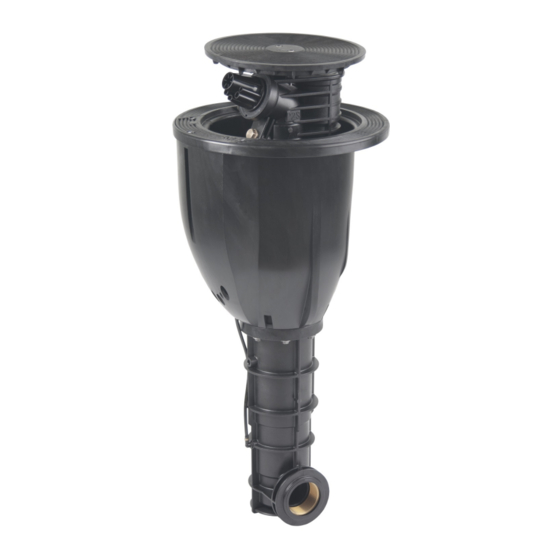
3. Description Jet direction 3.1 View from above Securing screw Cover for cable compartment Manual ON/OFF/Auto control module Securing screw Plug for decoder control Cover for Cable Cover compartment 3.2 Side view Manual control Housing Cable inlet opening Guide housing Main water connection (2") TDP074e.doc Rev. 28.11.2016 Page 5 / 29 Perrot REGNERBAU CALW GmbH Industriestraße 19‐29 / D‐75382 Althengstett / Germany – Tel.: +49‐7051‐162‐0 / Fax: +49‐7051‐162 133 E‐mail: perrot@perrot.de / Construction team e‐mail: technik@perrot.de ... -
Page 6: Special Tools
The pressure at the sprinkler may not exceed 10 bar Connection thread: G2 FT “ Liquids: Water Liquid temperature: 40 C max. Ambient temperature: 60 C max. For further data see separate data sheet. TDP074e.doc Rev. 28.11.2016 Page 6 / 29 Perrot REGNERBAU CALW GmbH Industriestraße 19‐29 / D‐75382 Althengstett / Germany – Tel.: +49‐7051‐162‐0 / Fax: +49‐7051‐162 133 E‐mail: perrot@perrot.de / Construction team e‐mail: technik@perrot.de ... -
Page 7: Assembly, Set-Up And Installation
5.1 Hazard warnings If any impurities get into the sprinkler, it is possible that the sprinkler could be destroyed and that fitters could be injured. Therefore flush out the line thoroughly before connecting the water supply. Any unexpected emergence of a jet of water can lead to serious injury. Therefore make sure that the installation has been fully completed before turning on the water supply. 5.2 Installation instructions The thread connection on the pop‐up sprinkler is 2" FT. For the thread seal use hemp and sealing compound, e.g. Fermit Spezial or teflon tape. The pop‐up sprinkler should be fitted in accordance with the 'Perrot VP3 pop‐ up sprinkler installation diagram' (see next page). In order to avoid any load pressure on the main line, you should definitely use a flexible connection. Providing a drainage pit directly connected to the drainage, as shown in the installation diagram, is very much recommended. For screwing in the connection joint the housing or housing edge of the pop‐up sprinkler can be firmly held or clamped. TDP074e.doc Rev. 28.11.2016 Page 7 / 29 Perrot REGNERBAU CALW GmbH Industriestraße 19‐29 / D‐75382 Althengstett / Germany – Tel.: +49‐7051‐162‐0 / Fax: +49‐7051‐162 133 ... -
Page 8: Vp3 Pop-Up Sprinkler Installation Diagram
Anschlussverschraubung 4 2 2 2 “ 75x2 FT “ 75x2 IG 5 Rohrstück PE‐HD 12,5 75 Pipe PE‐HD 12.5 75 1 1 1 “ “ 6 1 1 1 Bogen lang 90° Nr.1 2 IGxAG Elbow 90° no. 1 2 FTxMT TDP074e.doc Rev. 28.11.2016 Page 8 / 29 Perrot REGNERBAU CALW GmbH Industriestraße 19‐29 / D‐75382 Althengstett / Germany – Tel.: +49‐7051‐162‐0 / Fax: +49‐7051‐162 133 E‐mail: perrot@perrot.de / Construction team e‐mail: technik@perrot.de ... - Page 9 Sprinkler arrangement (schematic only) Detail X: Sprinkler arrangement upon installation VP3 sprinkler has to be installed in that way, that the top accessible cable box is on the side of the irrigated area. TDP074e.doc Rev. 28.11.2016 Page 9 / 29 Perrot REGNERBAU CALW GmbH Industriestraße 19‐29 / D‐75382 Althengstett / Germany – Tel.: +49‐7051‐162‐0 / Fax: +49‐7051‐162 133 E‐mail: perrot@perrot.de / Construction team e‐mail: technik@perrot.de ...
-
Page 10: Installation Scheme For Vp3 With Rubber Infill Lawn
5.4 Installation scheme for VP3 with rubber infill lawn TDP074e.doc Rev. 28.11.2016 Page 10 / 29 Perrot REGNERBAU CALW GmbH Industriestraße 19‐29 / D‐75382 Althengstett / Germany – Tel.: +49‐7051‐162‐0 / Fax: +49‐7051‐162 133 E‐mail: perrot@perrot.de / Construction team e‐mail: technik@perrot.de ... -
Page 11: Handling The Vp3 Pop - Up Sprinkler With Filled Synthetic Turf
5.4.1 Handling the VP3 pop‐up sprinkler with filled synthetic turf Remove plug so that the lid and the cable shaft cover can be disassembled / assembled see 8.6. Do not plug the drainage holes during adhesive bonding of the synthetic turf. 5.4.2 Operating instructions for VP3 pop‐up sprinkler with filled synthetic turf Operation of the manual control using an engineered flat‐blade screwdriver (1,1 mm x 9,0mm). Manual control can be opened by turning the engineered flat‐blade screwdriver through the cross shaped rubber protection see 6.2. Commissioning Turn to the left – AUTO position Turn to the right – OFF Approx. 1‐2 full rotation to the left – ON TDP074e.doc Rev. 28.11.2016 Page 11 / 29 Perrot REGNERBAU CALW GmbH Industriestraße 19‐29 / D‐75382 Althengstett / Germany – Tel.: +49‐7051‐162‐0 / Fax: +49‐7051‐162 133 E‐mail: perrot@perrot.de / Construction team e‐mail: technik@perrot.de ... -
Page 12: External Start Using Key Switch
5.5 External start using key switch There is a safety circuit with key‐operated switch for checking whether any unauthorized people are in the danger zone / area to be watered. The key‐operated switch gets fitted in a position from which the whole danger zone can be clearly seen. Watering begins only when the operator gives the all‐clear by turning the key. For details of how the controller works please refer to the separate TDP072 operating instruction. 5.6 Cabeling 3‐core cable laid during installation to the VP3 pop‐up sprinkler's electrical connection. The cable is pulled through the right or left opening on the bottom of the housing into the cable compartment. Proposal for pulling in the control cable into the sprinkler TDP074e.doc Rev. 28.11.2016 Page 12 / 29 Perrot REGNERBAU CALW GmbH Industriestraße 19‐29 / D‐75382 Althengstett / Germany – Tel.: +49‐7051‐162‐0 / Fax: +49‐7051‐162 133 E‐mail: perrot@perrot.de / Construction team e‐mail: technik@perrot.de ... - Page 13 The DBR/Y‐6 cable connector kit (article no.: ZH90032) for connecting the control cable to the coil fitted inside the sprinkler. Open the cover of the cable compartment and attach cable connector. Put back the cables into the cable compartment and close the cover. The electrical connection is thus not exposed to the soil, but is instead protectively integrated inside the sprinkler and accessible again at any time. This simplifies any search for faults and any maintenance work can be carried out at any time without any earthwork. TDP074e.doc Rev. 28.11.2016 Page 13 / 29 Perrot REGNERBAU CALW GmbH Industriestraße 19‐29 / D‐75382 Althengstett / Germany – Tel.: +49‐7051‐162‐0 / Fax: +49‐7051‐162 133 E‐mail: perrot@perrot.de / Construction team e‐mail: technik@perrot.de ...
- Page 14 Cable plan (schematic only) Control cable specification: Suitable for underground installation PVC insulated and EPDM sheated cable, NYY For VP3: NYY 2x2.5mm RE For further details please see separate operating instructions for Water Control (TDP072). TDP074e.doc Rev. 28.11.2016 Page 14 / 29 Perrot REGNERBAU CALW GmbH Industriestraße 19‐29 / D‐75382 Althengstett / Germany – Tel.: +49‐7051‐162‐0 / Fax: +49‐7051‐162 133 E‐mail: perrot@perrot.de / Construction team e‐mail: technik@perrot.de ...
-
Page 15: Commissioning And Operation
6.1 Potential danger When it starts up, the pop‐up sprinkler rises up out of the housing and builds up full pressure within about 5 seconds. The jet of water emitted can cause injury. For this reason the following guidance must be followed when commissioning and operating the sprinkler: When the sprinkler is being operated in automatic mode, there must be nobody present in the area. Operating personnel must not stand in the direction of the sprinkler's jet. The jet's direction is marked on the cover by an arrow. Jet direction Cover for cable compartment Figure 1 If the sprinkler is not installed flush with the ground, people may be injured by a fall as a result of stumbling or tripping. Therefore check prior to commissioning and regularly during ongoing use whether the sprinkler cover shuts flush with the surrounding ground. The sprinkler must not be operated without a closed cover for the cable compartment. During operation the sprinkler head props itself against the edge of the cover and cannot rotate freely without the cover. TDP074e.doc Rev. 28.11.2016 Page 15 / 29 Perrot REGNERBAU CALW GmbH Industriestraße 19‐29 / D‐75382 Althengstett / Germany – Tel.: +49‐7051‐162‐0 / Fax: +49‐7051‐162 133 E‐mail: perrot@perrot.de / Construction team e‐mail: technik@perrot.de ... -
Page 16: Commissioning
Slowly open supply of water to the sprinkler until operating pressure is built up. It is possible that the sprinkler will briefly open, but should then automatically close after at most 30 seconds. d) O nce the water supply has been opened and max. operating pressure has been reached, check sprinkler and connection for leaks. e) Check that sprinkler is working properly: Open sprinkler using <Manual opening> by moving the screw for <Manual opening> into the position between AUTO and OFF (approx. 1 rotation). Sprinkler head rises and starts to rotate. Do not stand in front of the nozzle opening! f) Close <Manual opening> and put into AUTO position (see point 6.2b). Sprinkler must stop water flow within 30 seconds. g) Keep repeating steps 'e' and 'g' until the sprinkler is working faultlessly. h) Check once again that it works correctly when activated electrically from the controller. TDP074e.doc Rev. 28.11.2016 Page 16 / 29 Perrot REGNERBAU CALW GmbH Industriestraße 19‐29 / D‐75382 Althengstett / Germany – Tel.: +49‐7051‐162‐0 / Fax: +49‐7051‐162 133 E‐mail: perrot@perrot.de / Construction team e‐mail: technik@perrot.de ... - Page 17 The following points 6.3, 6.4 and 6.5 should ideally be carried out with the sprinkler running. First fold out the safety catch to the side of the sprinkler head (see illustration 2) so that no limbs (e.g. fingers) can get jammed if the sprinkler should unexpectedly close. Cover Safety catch folded out Sprinkler head Safety catch folded in Housing Illustration 2 No special procedures are needed to set the sprinkler. All you need to set are the sprinkler's rotational speed and, when using it in back‐and‐forth mode, the sector to be watered. TDP074e.doc Rev. 28.11.2016 Page 17 / 29 Perrot REGNERBAU CALW GmbH Industriestraße 19‐29 / D‐75382 Althengstett / Germany – Tel.: +49‐7051‐162‐0 / Fax: +49‐7051‐162 133 E‐mail: perrot@perrot.de / Construction team e‐mail: technik@perrot.de ...
-
Page 18: Setting The Sector
Setting the sector With this pop‐up sprinkler the sector setting is infinitely variable. You can adjust the area to be watered by pulling on the relevant end of the top or bottom spring stop. Setting the sector angle Infinitely variable setting is possible by pulling (not pressing) on the relevant end of the top or bottom spring stop. Spring stop Spring stop Apply adjusting forces here Figure 3 TDP074e.doc Rev. 28.11.2016 Page 18 / 29 Perrot REGNERBAU CALW GmbH Industriestraße 19‐29 / D‐75382 Althengstett / Germany – Tel.: +49‐7051‐162‐0 / Fax: +49‐7051‐162 133 E‐mail: perrot@perrot.de / Construction team e‐mail: technik@perrot.de ... -
Page 19: Full-Circle Irrigation
For full‐circle irrigation the spring stops need to be removed. First, the sprinkler module needs to be removed from the housing. (See point 8.3). Pull spring stop apart at both ends only to such extent that they can just be slid off. If the spring stops get overextended, it will not be possible to use them any more for back‐and‐forth operation. Gently pull both spring stops apart and remove downwards. Now splay the spring stops over the sliding pipe and pull off. New spring stops are fitted in reverse order. Any overextension of the spring stops must be avoided, as otherwise it can no longer be certain that they will fit tightly and it will no longer be possible to set the irrigation sector's switch‐over point when reverting to sector operation. TDP074e.doc Rev. 28.11.2016 Page 19 / 29 Perrot REGNERBAU CALW GmbH Industriestraße 19‐29 / D‐75382 Althengstett / Germany – Tel.: +49‐7051‐162‐0 / Fax: +49‐7051‐162 133 E‐mail: perrot@perrot.de / Construction team e‐mail: technik@perrot.de ... -
Page 20: Regulating The Speed
Regulating the speed Turning the regulating screw to the right reduces the rotational speed. Option: It is possible for the sprinkler to be completely stopped when the speed‐ regulating screw is turned to the right. If you turn it to the left, the rotational speed gets increased again. Irrigate at reduced speed only if the water is clear. If the water is dirty, the regulating screw must remain fully opened. Otherwise there is a risk of the sprinkler stopping. Figure 4 Regulating screw TDP074e.doc Rev. 28.11.2016 Page 20 / 29 Perrot REGNERBAU CALW GmbH Industriestraße 19‐29 / D‐75382 Althengstett / Germany – Tel.: +49‐7051‐162‐0 / Fax: +49‐7051‐162 133 E‐mail: perrot@perrot.de / Construction team e‐mail: technik@perrot.de ... -
Page 21: Decommissioning And Preparing For Winter
20°C, it will take around 15 minutes until the – drive is thawed out. Electrically activate the solenoid several times so that any residual water is pushed out of the coil cavity. During the winter we recommend activating the coil for approx. 1 minute twice a week. 7.2 Springtime commissioning As a result of the change of load and diverse installation conditions (damp/dry), the head of the piston sprinkler is subjected to extreme tensions. These circumstances can lead to the piston acquiring some axial play. In order to avoid any operating problems, the piston drive cover should be tightened as described below during spring commissioning in the first and second year of operation. Before the grey cover can be tightened, the lock screw needs to be removed. After firmly tightening the grey cover, twist in the lock screw again. The lock screw prevents the grey cover from working itself loose. TDP074e.doc Rev. 28.11.2016 Page 21 / 29 Perrot REGNERBAU CALW GmbH Industriestraße 19‐29 / D‐75382 Althengstett / Germany – Tel.: +49‐7051‐162‐0 / Fax: +49‐7051‐162 133 E‐mail: perrot@perrot.de / Construction team e‐mail: technik@perrot.de ... - Page 22 Tighten cover using face spanner ZB98236 and approx. 10Nm of torque. That means, with a lever length of 10cm you need to apply a force of 100N to the spanner. Note: After the third or fourth winter there should be no further expansion. Bracing ribs Caution: If the lock screw cannot be screwed in, it will hit a piston drive bracing rib! In this case, the grey cover must be tightened a bit more so that the lock screw misses the bracing rib. The orientation of the bracing ribs is indicated by marker points. Marker points TDP074e.doc Rev. 28.11.2016 Page 22 / 29 Perrot REGNERBAU CALW GmbH Industriestraße 19‐29 / D‐75382 Althengstett / Germany – Tel.: +49‐7051‐162‐0 / Fax: +49‐7051‐162 133 E‐mail: perrot@perrot.de / Construction team e‐mail: technik@perrot.de ...
-
Page 23: Maintenance And Repair Work
8.1 Maintenance After one year of use, tighten the M6 flange screws (8 of them) using a 10mm box spanner to ensure that the sprinkler module is fixed firmly in place. Tightening torque 9 Nm. Clean out the inside of the sprinkler housing using an industrial vacuum cleaner or similar (as necessary). Cut sprinkler housing free of any overgrowing grass. It makes sense to carry out these jobs prior to spring commissioning. Regularly check that the sprinkler is flush with the surface, especially in the case of natural grass. 8.2 Replacing the nozzle Nozzle sealing ring Nozzle Relief nozzle for control water Flange screw tightening torque: 9 Nm Figure 5 TDP074e.doc Rev. 28.11.2016 Page 23 / 29 Perrot REGNERBAU CALW GmbH Industriestraße 19‐29 / D‐75382 Althengstett / Germany – Tel.: +49‐7051‐162‐0 / Fax: +49‐7051‐162 133 E‐mail: perrot@perrot.de / Construction team e‐mail: technik@perrot.de ... - Page 24 When changing the main nozzle the nozzle's thread should be cleaned and greased. This enables the nozzle to be easily loosened by hand (using the assembly key RB25189) and just as easily tightened again. When fitting the nozzle make sure that the funnel gets pushed on in the right position. (See picture.) Right position Wrong position If the funnel is not properly fitted first, the nozzle cannot be screwed into the manifold head. When fitting the new nozzle, make sure that the nozzle gets fully screwed in, that the main secondary nozzle points downwards (6 o'clock position) and that the sealing ring is correctly fitted (figure 5). TDP074e.doc Rev. 28.11.2016 Page 24 / 29 Perrot REGNERBAU CALW GmbH Industriestraße 19‐29 / D‐75382 Althengstett / Germany – Tel.: +49‐7051‐162‐0 / Fax: +49‐7051‐162 133 E‐mail: perrot@perrot.de / Construction team e‐mail: technik@perrot.de ...
-
Page 25: Removing The Valve Insert
8.3 Removing the valve insert The sprinkler module needs to be taken out of the housing in order to carry out the repairs described below. Unscrew cover using 5mm Allen key. Remove the 8 flange screws using a 10mm box spanner. Flange screw tightening torque 9 Nm Figure 6 Pull sprinkler module out of the housing. Remove retaining ring in the housing bottom using removal hook RT17839. Screw valve lifter RT25359 in the housing base onto the valve and pull upwards. It is possible that for this a few gentle hits may be necessary in order to take off the valve. TDP074e.doc Rev. 28.11.2016 Page 25 / 29 Perrot REGNERBAU CALW GmbH Industriestraße 19‐29 / D‐75382 Althengstett / Germany – Tel.: +49‐7051‐162‐0 / Fax: +49‐7051‐162 133 E‐mail: perrot@perrot.de / Construction team e‐mail: technik@perrot.de ... -
Page 26: Fitting The Valve Insert
Using pliers RT17844, now fit the retaining ring into the groove provided for it above the thrust washer. The sprinkler insert is fitted in reverse order. 8.5 Cleaning the piston drive and piston drive chamber If due to becoming very dirty the drive is no longer working, the piston drive should be taken out and cleaned. Removing the piston drive: See repair guide TDP055‐rep. 8.6 Removal / installation of the control unit Ensure sprinkler is not under pressure. Taking out the control unit Lift cover and fix with safety catch. Safety catch Undo all 3 locking screws and take off cable compartment cover. Unclip control unit from protective casing and lift up. TDP074e.doc Rev. 28.11.2016 Page 26 / 29 Perrot REGNERBAU CALW GmbH Industriestraße 19‐29 / D‐75382 Althengstett / Germany – Tel.: +49‐7051‐162‐0 / Fax: +49‐7051‐162 133 E‐mail: perrot@perrot.de / Construction team e‐mail: technik@perrot.de ... - Page 27 Twist out coil. When replacing the control unit, press back the mounting ring at the plug‐in connector and pull out the hose. Control unit Sprinkler Fitting the control unit When buying a replacement part, the control unit is supplied with plug‐and‐socket connections. Push hoses into plug‐in grommets as far as they will go and ensure that the mounting ring springs back. Screw in coil. Clip control unit into protective casing. Secure housing cover using all three screws. Check sprinkler is working properly as per point 6.2. TDP074e.doc Rev. 28.11.2016 Page 27 / 29 Perrot REGNERBAU CALW GmbH Industriestraße 19‐29 / D‐75382 Althengstett / Germany – Tel.: +49‐7051‐162‐0 / Fax: +49‐7051‐162 133 E‐mail: perrot@perrot.de / Construction team e‐mail: technik@perrot.de ...
-
Page 28: Troubleshooting
Valve fails to open even with blocked hole manual opening Supply line under no / insufficient Establish pressure supply pressure Coil seat dirty Clean coil seat Bits of dirt between valve seat and Clean valve seat and sealing sealing plate plate Valve fails to close Remove valve and replace Defective membrane membrane Control water filter dirty Clean control water filter Output pressure at sprinkler Stones and bits of dirt are hindering Clean valve and flush sprinkler an unimpeded passage of water nozzle too low or casting range too short Valve insert is blocked Clean valve insert see point 8.3 We reserve the right to make changes in line with technological advances, including without prior notification. TDP074e.doc Rev. 28.11.2016 Page 28 / 29 Perrot REGNERBAU CALW GmbH Industriestraße 19‐29 / D‐75382 Althengstett / Germany – Tel.: +49‐7051‐162‐0 / Fax: +49‐7051‐162 133 E‐mail: perrot@perrot.de / Construction team e‐mail: technik@perrot.de ... - Page 29 Original versions of the operating instructions for the machine and of the technical documentation have been provided. This declaration of conformity loses its validity if any modifications are made to the machine that we have not first agreed and approved in writing. Althengstett, 20.05.2014 Günther Flik, Director of Engineering _____________ _____________________________________ __________________ Date Signatory and signatory's details Signature TDP074e.doc Rev. 28.11.2016 Page 29 / 29 Perrot REGNERBAU CALW GmbH Industriestraße 19‐29 / D‐75382 Althengstett / Germany – Tel.: +49‐7051‐162‐0 / Fax: +49‐7051‐162 133 E‐mail: perrot@perrot.de / Construction team e‐mail: technik@perrot.de ...
Need help?
Do you have a question about the VP3 VAC and is the answer not in the manual?
Questions and answers