
Related Manuals for CycleOps PowerTap SLC+


Summary of Contents for CycleOps PowerTap SLC+
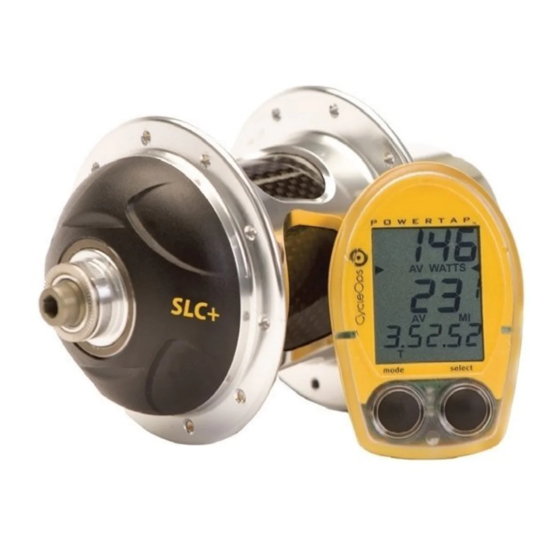
- Page 1 USER GUIDE PowerTap SLC+ PowerTap SL+ PowerTap Pro+ PowerTap Elite+ PowerTap 2.4+ PowerTap SLC+ Featured...
- Page 2 Copyright Copyright 2008. All rights reserved. No part of this publication may be copied, photographed, reproduced, translated, transmitted electronically or placed on digital media without the prior written consent of Saris Cycling Group, Inc. Trademarks Saris Cycling Group, Inc , PowerTap and the PowerTap logo, are all registered trademarks of Saris Cycling Group, Inc.
-
Page 3: About This User Guide
With an accurate measure of intensity, you can precisely balance the stress of training and your body’s response. This User Guide describes the proper use and maintenance of your CycleOps PowerTap. For more information about training and performance please go to www.cycleops.com. -
Page 4: Table Of Contents
Table of Contents Computer Setup..23 About this User Guide Important Precautions..5 Computer Setup Main Menu..23 Computer Setup 1..24 System Overview..7 Computer Setup 2..27 The PowerTap System..7 Preparing for Installation..7 Computer Setup 3..28 Computer Setup 4..29 Compatibility..8 Wheel Building..8 Computer Setup 5..31 ANT+Sport..33 System Installation..9 General Computer Operation..11... -
Page 5: Important Precautions
Important Precautions: • Before beginning any exercise program, consult your physician. • Keep your eyes on the road. Do not become overly engaged with the PowerTap display. We recommend familiarizing yourself with computer functions while stationary. • The computer, chest strap, and hub are water resistant, not water proof. - Page 6 • The PowerTap wheel does not include a quick release skewer. • Failure to adhere to these precautions may cause premature failure or incorrect operation of the unit and may void the warranty. Please register your PowerTap at www.cycleops.com. IMPORTANT: For your safety, the non-drive side of the PowerTap hub must be built with at least a 2x lacing pattern.
-
Page 7: System Overview
System Overview THE POWERTAP SYSTEM The PowerTap system includes a power-measuring hub which measures torque and wheel speed. This information is transmitted to a computer mounted on the handlebar or stem. Heart rate data is transferred via a coded telemetry signal from the chest strap monitor. -
Page 8: Compatibility
System Overview cont. COMPATABILITY The PowerTap hub is compatible with Shimano 8, 9, and 10 speed systems or Campagnolo 8, 9, and 10 speed systems. Freehub bodies may be interchanged. Reference FREEHUB REPLACEMENT for further instructions. The PowerTap is available in 130mm (Road) and 135mm (MTB) axle lengths. Only insert the correctly spaced PowerTap hub into your frame. -
Page 9: System Installation
System Overview cont. SYSTEM INSTALLATION 1. Insert Wheel Into Frame Insert the PowerTap wheel into the frame. Make sure the axle is correctly positioned in the dropouts and secure the wheel in place with a skewer. 2. Attach Computer Shoe to Handlebar or Stem The shoe can be mounted on either the handlebar or stem. - Page 10 3. Place Computer into Shoe FIGURE 5 Place the computer into the computer shoe on the handlebar or stem. Line up the slots on the base of the computer with the bracket and slide computer toward the rider (FIGURE 5). NOTE: Ensure the computer is fully inserted onto the receiver shoe to prevent accidental removal.
-
Page 11: General Computer Operation
General Computer Operation DISPLAY LEVELS The computer has three (3) main display levels: TRANS. POWER ICON DISPLAY Power WATTS Middle Speed SPEED INTERVAL DISPLAY Bottom Multi-Function DISPLAY 58.I0 MULTI - FUNCTION NOTE: These locations only apply to trip and DISPLAY interval modes and do not apply to Cycle Computer or Heart Rate Monitor... -
Page 12: Clearing Data
2) Hold [MODE] or [SELECT] - a single button press and hold of either [MODE] or [SELECT] for 2 sec. Used for initiating a new mode or function. 3) Press [MODE] and [SELECT] - simultaneously press and release of both [MODE] and [SELECT]. -
Page 13: Finding Sensors
FINDING SENSORS The PowerTap hub, sensors and computer are "paired" or "learned" at the factory so that the sys- tem is ready to ride once installed on the bicycle. Learning involves viewing and storing each device ID into the PowerTap computer. Information on learning can be found in computer setup 5 section of this owner's manual. -
Page 14: Computer Navigation
Computer Navigation MODE SELECT Press [MODE] to scroll through the various functions of the dis- button button play. Press [SELECT] to toggle through the various options within that funciton. Note: Peak power and Time in Zones infor- Power MX, AV, WATTS Speed MX, AV mation is only available on the SLC+, SL+, Pro+ and 2.4+... -
Page 15: Torque Function
TORQUE FUNCTION FIGURE 12 Shows the torque placed on the hub in inch-pounds. To display torque while in trip mode: 1) Press [MODE] to scroll the cursor to the top line of the main display. 58.I0 2) Press [SELECT] until the current power function is displayed. 3) Hold [SELECT] until the word “WATTS”... -
Page 16: Speed Function
SPEED FUNCTION The middle level of the main display shows current, max, and average speed readings. 1) Press [MODE] to scroll the cursor to the middle line of the main display. 2) Press [SELECT] to toggle through the speed function options. FIGURE 13 Current Speed Speed is displayed in either miles per hour (MI) or kilometers per hour (KM) up to... -
Page 17: Multi-Function
FIGURE 16 MULTI-FUNCTION DISPLAY WATTS Distance (D) Total trip or the selected interval distance in interval mode is displayed in miles or kilometers from 0.00 to 999.99 (FIGURE 16). 58.I0 1) Press [MODE] to scroll the cursor to the bottom line of the main display. 2) Press [SELECT] to toggle through the multi-function displays until the “D”... - Page 18 Cadence (C) FIGURE 18 Cadence is measured at the hub by analyzing the way a rider applies torque through the pedal stroke since there are natural power differences in the pedal WATTS stroke. The rate of pedaling is shown from 40 to 240 RPM. NOTE: An optional wireless cadence sensor is available to measure cadence at the crank.
- Page 19 Average Cadence (C & AVG) FIGURE 19 The average cadence displays data since the last time data was cleared in trip mode or the selected interval in interval mode. Average cadence is displayed in RPM. WATTS 1) Press [MODE] to scroll the cursor to the bottom line of the main display. 2) Press [SELECT] to toggle through the multi-function displays until the “C”...
-
Page 20: Time In Zones
Heart Rate ( FIGURE 22 Current heart rate is shown up to 255 beats per minute (BMP). You must wear the heart rate chest strap to enable the heart rate measurement function. NOTE: The PowerTap uses a coded chest strap. Elite + users must purchase an ANT+ compat- WATTS ible chest strap for this function to operate. -
Page 21: Peak Power
FIGURE 25 PEAK POWER (SLC+, SL+, PRO+ AND 2.4+ ONLY) Peak power displays your maximum average power for various time intervals. WATTS 1) Press [MODE] to scroll the cursor until the middle line shows PP. 2) Press [SELECT] to toggle through the different time intervals 0:30, 1:00, 5:00 and 20:00. -
Page 22: Interval Memory Mode
INTERVAL MEMORY MODE To access stored interval data for the previous 9 intervals only: 1) Enter the interval mode hold [MODE] until “INT” appears on the left hand side of the display. 2) Press [MODE] to scroll until the “INT” flashes. NOTE: INT now constitutes a fourth level of dis- play. -
Page 23: Computer Setup
6.0 version of NOTE: The version of firmware is displayed upon startup. The firmware. most updated firmware version is available at www.cycleops.com. (FIGURE 28) 2) Extended hold of [MODE] and [SELECT] simultaneously enters computer setup function. NOTE: Continue to hold through “clr”... -
Page 24: Computer Setup 1
COMPUTER SETUP 1 This setup menu includes: time of day, date, storage rate, wheel circumference, units of measure, odometer and lactic threshold. NOTE: You are unable to move back to previously viewed set- tings. You must restart setup 1 to make corrections. You may hold [MODE] and [SELECT] to save and exit setup. - Page 25 5) Press [SELECT] to toggle through digit values to set minutes in time of day. Press [MODE] to save. Year 6) Press [SELECT] to toggle through digit values to set year, month, and date. Press [MODE] to save. 0 1 - 0 1 Month 7) Press [SELECT] to toggle through storage rate values (1, 2 seconds).
- Page 26 TABLE 4 - Common Wheel Circumferences 9) Press [SELECT] to toggle between English or Metric units. Press [MODE] to save. 10) Press [SELECT] to set starting odometer reading. Press [MODE] to save. NOTE: Odometer settings are saved during battery changes. 0 0 0 0 0...
-
Page 27: Computer Setup 2
COMPUTER SETUP 2 (SLC+, SL+, Pro+ and 2.4+ only) This setup menu includes: rate of display for watts, speed, and cadence. NOTE: You are unable to move back to previously viewed settings. You must restart setup 2 to make corrections. NOTE: These settings do not effect the data stored for download. -
Page 28: Computer Setup 3
COMPUTER SETUP 3 This setup menu includes: zero readings for power, speed, and cadence. NOTE: You are unable to move back to a previously viewed setting. You must restart setup 3 to make corrections. NOTE: These settings are useful for determining you average power reading when pedaling only and do not effect the data that is stored for download. -
Page 29: Computer Setup 4
COMPUTER SETUP 4 This setup menu includes: sleep time, locations of display, cadence source, cycle computer mode, heart rate monitor, and auto start/stop. From this menu you are unable to move back to previ- ously viewed settings. You must restart setup 4 to make corrections. 1) From the computer setup main menu press [SELECT] and scroll until the number four (4) is flashing and press [MODE] to enter setup mode. - Page 30 5) The PowerTap can be used as a cycle computer or heart rate monitor. Press [SELECT] to toggle through mode options. watts watts, mi, and ( ) = power meter mode mi, and ( ) = cycle computer mode ( ) = heart rate monitor mode Press [MODE] to save.
-
Page 31: Computer Setup 5
COMPUTER SETUP 5 This setup allows the CPU to learn a new device or sensor such as the hub, heart rate strap and optional cadence sensor. NOTE: This process only needs to be used if a new sensor or hub is being used in conjunction with your CPU or vice versa. - Page 32 5) Follow the above steps for any additional sensors you may be using, such as the heart rate strap, speed and cadence sensors. The sensor name is shown on the top line of the display. SPd = speed sensor Cd = cadence sensor HS = heart rate sensor Press [SELECT] to toggle through the digit values to get the I.D.
-
Page 33: Ant+Sport
ANT+Sport The PowerTap + Series uses ANT+Sport wireless technology that allows you to use the PowerTap with other ANT+Sport Power devices. The Garmin Edge 705 is one such device. In order to pair your PowerTap + Series hub with a Garmin Edge 705, follow these instructions or contact Garmin. -
Page 34: Maintenance & Specifications
Maintenance & Specifications The following information will help you keep your PowerTap running properly. If you are not familiar with hub maintenance please consult a professional bicycle mechanic before servicing. During the course of any repair do not remove the torque tube. There are no user serviceable parts inside. -
Page 35: Freehub Replacement
-Buzzy’s Slick Honey Grease -Mobilgrease 28 Warning: Failure to use the proper grease on the freehub pawls could result in engagement problems. FREEHUB REPLACEMENT - ELITE+, PRO+ OR ANY POWERTAP WITH A 12MM AXLE -See Figure 28 for illustrations -Use 5mm hex wrench and 17mm bike wrench and remove both end nuts from the axle. -Remove the axle -Remove the freehub and spacers. - Page 36 12MM AXLE ONLY Aluminum spacer Aluminum spacer installed here. installed here. FIGURE 28 Aluminum spacer No aluminum spacer. installed here...
-
Page 37: Computer Batteries
FIGURE 29 COMPUTER BATTERIES The PowerTap SL2.4 has batteries in the hub and computer. Computer batter- ies typically need to be changed every 400 hours of use. The computer will also say “low bat” when the computer battery needs to be changed. This mes- sage is displayed after a “clr”... -
Page 38: Hub Batteries
DATA TRANSMITION The hub transmits data on both the Saris network and the Ant Sport network simultaneously. Data transmitted on the Saris network: - Applied Power + orque - Speed (Angular Vtelocity) - Distance (Wheel Rotations) - Cadence - Hub Battery Condition Data transmitted on the Ant Sport network: Power Only Message - Power... -
Page 39: Test Mode
-Slide the battery pack back into position along the center core. As the pack is engaged a small increase of resistance to installation should be felt as the electrical connections are made. - Thread the cap all the way back on. - Replacement O-rings and battery packs are available from Saris Cycling Group. - Page 40 4 - Standard Test File This mode writes a small test file to the memory. Press [SELECT] and the bottom lines says “run” and then “yes” when the file is written. This file can then be downloaded. 5 - Communication Loop Back Test When looking at the front side of the computer, use a coin or paper clip to short out the two pins on the left side.
-
Page 41: Troubleshooting
Troubleshooting No display on computer screen · Computer is asleep – Press [MODE] or [SELECT] on the computer to wake up the computer. · Batteries need replacement - replace the computer batteries as shown in the maintenance section of the User Manual. ·... -
Page 42: Warranty
User Manual. Warranty CycleOps PowerTap is warranted to the original retail purchaser to be free from defects in materi- als and workmanship. Warranty coverage is valid to the original purchaser only and proof of pur- chase will be required. -
Page 43: Procedures
2. Saris Cycling Group will replace any unit that is structurally defective with a new unit or replace the unit with a unit of equal value. 3. In the event a product cannot be repaired, Saris Cycling Group will apply a limited credit reim- bursement toward another CycleOps PowerTap product of equal or greater value. -
Page 44: Glossary
Glossary Computer - Refers to the yellow handlebar or stem mounted device. Heart Rate (HR) - This displays current HR. Max and average values are displayed if [MAX] or [AVG] is selected. Watts - Real-time display of the effort you are putting in to pedaling the bike. This is your power reading. -
Page 45: Powertap Sl Computer Navigation
POWERTAP SL COMPUTER NAVIGATION MAIN MENU Hold [MODE] INTERVAL MODE Peak Power Time In Zones Press [MODE] Hold [SELECT] INTERVAL MEMORY MODE Press [SELECT] Press [SELECT] Press [MODE] Press [MODE] 1:00 Press [SELECT] Press [SELECT] Top Display Middle Display Bottom Display 5:00 Press [SELECT] Hold [SELECT]...
Need help?
Do you have a question about the PowerTap SLC+ and is the answer not in the manual?
Questions and answers