Advertisement
2-output DALI controller
1. USE
This device is a power unit used for managing DALI/DSI lighting and
ventilation loads.
It must be connected to one or more detectors and/or "pushbutton
type" diverted auxiliary controls in order to operate.
It has 3 main operating modes:
- "Corridor side/window side": 3 modes
- "Surrounding area": 1 mode
- "Synchronised": 1 mode (used in public buildings)
page 4
2. TECHNICAL FEATURES
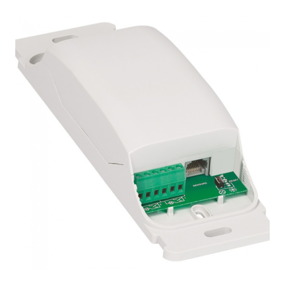
Green indicators:
Indicate the 5 operating modes
Green indicator:
Indicates the learning or RESET phase
Button: RESET or
select from the 5 operating modes
N/ /L1
+ 45°C
- 5°C
DALI/DSI
(16x2) max/out
230 V~
1000 VA
4,3 A
110 V~
Technical data sheet: S000067167EN-3
details on page 4
details on page 4
details on
NO/C/NC
1 x 500 VA
2.1 A
1 x 250 VA
Updated on: 24/08/2015
87045 LIMOGES Cedex
Telephone: (+33) 05 55 06 87 87 - Fax: (+33) 05 55 06 88 88
Catalogue number(s): 0 488 51
CONTENTS
1. Use . . . . . . . . . . . . . . . . . . . . . . . . . . . .1
2. Technical features . . . . . . . . . . . . . . . .1
3. Overall dimensions. . . . . . . . . . . . . . . .2
4. Connection . . . . . . . . . . . . . . . . . . . . . .2
5. Installation . . . . . . . . . . . . . . . . . . . . . .3
6. Operation . . . . . . . . . . . . . . . . . . . . . . .4
7. Parameter setting . . . . . . . . . . . . . . . . .5
8. Maintenance. . . . . . . . . . . . . . . . . . . . .5
9. Standards . . . . . . . . . . . . . . . . . . . . . . .5
2. TECHNICAL FEATURES (continued)
Voltage: 100-240 V~
Frequency: 50/60 Hz
No load power consumption: 1.5 W
Wiring:
- Power:
N
L: 2 x 2.5 mm
(screw terminals)
2
N
: 2 x 2.5 mm
via bistable relay (screw terminals)
2
NO C NC: 2 x 1.5 mm
via bistable relay (screw terminals)
2
- Control:
Pushbuttons: 1 x 1.5 mm² (screw terminals)
(100 m max. between the controller and the
pushbutton)
DALI/DSI ballast: 1 x 1.5 mm² (screw terminals)
(16 ballasts max. per channel) the distance
depends on the type of cable used.
The product is specifically for DALI or DSI,
which is selected automatically.
Connection between detector and controller: RJ 45 cord or cable
or BUS/SCS cable to be fitted with RJ 45 connector (150 m max.
between the controller and the furthest detector)
Product installation: in a suspended ceiling or on a suitable cable tray
BUS detectors:
- Infrared or ultrasound technology or dual technology
- Max. 6 detectors at 110/230 V~
Pushbutton: - Via normally open contact
- Can be used with an indicator: voltage, 27 V= to display
the state of the load in synchronised mode
Note: It is advisable not to exceed 5 pushbuttons per
channel (consumption of indicators)
Usage temperature: -5°C to +45°C
Storage temperature: -20°C to +70°C
Weight: 256 g
Impact resistance: IK04
Penetration by solid and liquid matter: IP20
Page
Created on: 10/01/2012
1/4
Advertisement
Table of Contents

Related Manuals for LEGRAND 0 488 51


Summary of Contents for LEGRAND 0 488 51
- Page 1 87045 LIMOGES Cedex Telephone: (+33) 05 55 06 87 87 - Fax: (+33) 05 55 06 88 88 2-output DALI controller Catalogue number(s): 0 488 51 CONTENTS Page 1. Use ......1 2.
-
Page 2: Overall Dimensions
2-output DALI controller Catalogue number(s): 0 488 51 3. OVERALL DIMENSIONS 4. CONNECTION (continued) 4.1 Wiring 1 (on a single phase) Ventilation /OUT max. /OUT max. 4. CONNECTION The NC C NO ( ) output on the controller is always associated with the presence information on the detectors. -
Page 3: Installation
2-output DALI controller Catalogue number(s): 0 488 51 4. CONNECTION (continued) 5. INSTALLATION 4.2 Wiring 2 (on 2 phases) Mounting Ventilation On cable tray max. max. 230/110 V: x 6 max. The two channels are synchronised, which enables the luminaires to be placed in staggered rows with one ballast supply phase on each channel. -
Page 4: Operation
DALI2 DALI1 RCA 2-output DALI controller Catalogue number(s): 0 488 51 DALI2 6. OPERATION 6. OPERATION (continued) 6.1 Corridor side - window side operating mode: 6.2 Surrounding area operating mode: Mode 5 Mode 1 - Mode 2 - Mode 3... -
Page 5: Parameter Setting
2-output DALI controller Catalogue number(s): 0 488 51 6. OPERATION (continued) 7. PARAMETER SETTING Detector When connecting the detector(s) to the controller it must be switched This controls the switching on and off of the two lighting circuits and off.
Need help?
Do you have a question about the 0 488 51 and is the answer not in the manual?
Questions and answers