Advertisement
Quick Links
Advertisement

Related Manuals for LEGRAND 0 766 22


Summary of Contents for LEGRAND 0 766 22
- Page 1 SECURE WANDERING SYSTEM INSTALLATION AND USER GUIDE...
- Page 3 Contents INSTALLATION PRINCIPLE COMMISSIONING System description Factory settings Settings DEVICE PRESENTATION AND Adjusting the antennae INSTALLATION OPERATION Secure wandering device Secure wandering system - auxiliary elements Operation in day mode (surveillance) Operation in night mode (intruder) STANDALONE INSTALLATION Illuminated and audible signals Example of installation CHARACTERISTICS Wiring - controllers and antennae...
- Page 4 Cat. No. 0 766 06 configured Legrand products must only be opened and repaired for this function. This way nurses are immediately by personnel trained and authorised by Legrand.
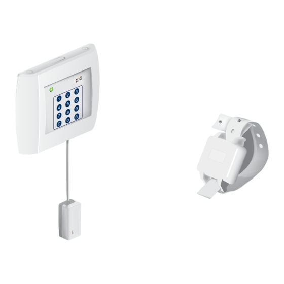
- Page 5 Indicates that a door has been crossed by a resident fitted with a wristband Cat. No. 0 766 20. Works with door unit Cat. No. 0 766 06 configured for secure wandering which allows acknowledgement and feedback to the Legrand SCS nurse call unit system. Door controller Cat. No. 0 766 22 Technical characteristics •...
- Page 6 The antenna activity is permanently checked by the controller. Technical characteristics • Power supply: via door controller Cat. No. 0 766 22 • Dimensions (H x W x D): 50 x 100 x 40 mm • Screwed onto the wall •...
- Page 7 Wristband number: controller last 3 characters. Cat. No. 0 766 22. To be entered for the 9010 and 9011 code settings. Worn on the wrist or the ankle, this waterproof wristband is fitted with an eyelet fastening preventing it from being taken off by the person under surveillance.
- Page 8 • Cable type (to controllers 0 766 22): 1 x 0.9 mm pair The magnetic opening sensor must be connected to the “DOOR” input of controller 0 766 22. Surveillance mode: an escape alarm is only generated on the double condition that a wristband and opening of the door are both detected.
- Page 9 0 766 21 The controller with built-in antenna (15W30 -->) Cat. No. 0 766 22 is normally installed in the immediate vicinity of the exit door, at a height which allows easy access to the keypad (1.20 m). Antenna Cat. No. 0 766 21 is installed at a height of around 50 cm opposite the controller.
- Page 10 Selecting a door release or lock: • Door release: flush-mounted installation - Cable type (to controller 0 766 22): 2 x 1.5 mm - Cat. No. 0 408 95: undervoltage door release 12 V= - 600 mA. For operation at emergency exits - Cat.
- Page 11 WIRING - CONTROLLERS AND ANTENNAE 0 766 22 ALARM 0 431 00 / 3511 DOOR LOCK CHAPERONE CONF 4 131 05 1 2 3 4 DCIN MODE 5 6 7 8 200 m max. 0 766 21 CONTENTS...
- Page 12 Standalone installation OPERATING MODES Chaperone Mode selection The controller must be set to chaperone mode in The changeover from surveillance mode to intruder order to allow a wristband wearer to go through an exit mode and back can depend on the state of its wired without setting off the alarm.
- Page 13 The controller Cat. No. 0 766 22 with built-in antenna (15W30 -->) is normally installed in the immediate vicinity of the exit door, at a height that allows easy access to the keypad (1.20 m). Antenna Cat. No. 0 766 21 is installed at a height of around 50 cm opposite the controller.
- Page 14 Selecting a door release or lock: • Door release: flush-mounted installation - Cable type (to controller 0 766 22): 2 x 1.5 mm - Cat. No. 0 408 95: undervoltage door release 12 V= - 600 mA. For operation at emergency exits - Cat.
- Page 15 WIRING - CONTROLLER/ANTENNAE AND DOOR UNIT Door unit 0 766 06 8 0 to 9 0 766 22 ALARM 0 431 00/ DOOR 3511 0 766 06 LOCK CHAPERONE 15 16 17 18 19 20 CONF DCIN MODE 1 2 3 4...
- Page 16 System installation (continued) OPERATING MODES Chaperone Mode selection The controller must be set to chaperone mode in order The changeover from surveillance mode to intruder to allow a wristband wearer to go through an exit without mode and back can depend on the state of its wired setting off the alarm (chaperone period to be set).
- Page 17 • User language: English • System link protocol: 2G anti-wandering system • No code filtering (surveillance for all wristbands) • Immediate restart for the alarms: 20 sec. time delay (value 0) Default configurator position 0 766 22 0 766 21 ALARM PORTE VERROU...
- Page 18 Commissioning (continued) PARAMETER SETTING The parameters can easily be set for the system using simple codes which provide access to the different parameter-setting steps. Important: The system must be put in parameter-setting mode before codes are entered on the keypad by entering the access code on the keypad (9039E) in parameter-setting mode.
- Page 19 Code Setting 9005 Mode change mechanism: Allows the user to choose whether the changeover from intruder mode to surveillance mode is performed by entering codes on the keypad (value 1) or by analysing the mode selection input (value 0). Example: Mode selection by entering codes on the keypad: 9005 E 1 E 9006 Locking control: Operation with locking control (value 0) or with release control (value 1).
- Page 20 Commissioning (continued) SETTING THE ANTENNAE Due to the low power level radiated by the wristband transmitters, the sensitivity level of the antenna must be set under conditions that are as close as possible to normal system usage. Proceed as follows in order to set the antenna: •...
- Page 21 Operation OPERATION IN DAY MODE (SURVEILLANCE) This mode is activated using code 9031 (only if code 9005 E 1 E has been confirmed beforehand) or via a time switch connected to the “MODE” terminals. The controller must generate an alarm if a resident fitted with a wristband escapes. When in rest mode, the power supply indicator light is on constantly and the operation indicator light is off.
- Page 22 Operation (continued) OPERATION IN NIGHT MODE (INTRUDER) This mode is activated using code 9030 (only if code 9005 E 1 E has been confirmed beforehand) or via a time switch connected to the “MODE” terminals. This mode is used when the controller needs to generate an alarm if the exit is opened or passed through by anyone (with or without a wristband).
- Page 23 ILLUMINATED AND AUDIBLE SIGNALS Illuminated signal: The controller status is indicated via two indicator lights. A continuously lit green indicator light indicates that the system power is on. Flashing indicates that there is a system fault which requires the controller and the antennae to be checked. The yellow operation indicator light shows the system status with different types of flashing (see the diagram below).
- Page 24 Characteristics SPECIFICATIONS Power supply: Volt-free contact outputs: • 12 to 24 V= • Locking: 1 A - 24 VA/60 V= max • 150 mA • Alarm: 1 A - 24 VA/60 V= max Illuminated signals: Wristband: • System power ON •...
- Page 25 • 2 - E (confirmation) - C: for cancelling an entry being made Code Control Default acknowledgement code Example: 369 E (used to acknowledge controller Cat. No. 0 766 22). 9030 Switch to night mode (intruder)* 9031 Switch to day mode (surveillance)*...
- Page 26 Controller configuration Checking the controller parameters The controller parameters can be checked by connecting it to a PC (set as hyperterminal). For more information, contact customer service. Female RS232 CONTENTS...
- Page 27 CONTENTS...
- Page 28 Head office: 128, av. du Maréchal-de-Lattre-de-Tassigny 87045 Limoges Cedex - France tel: +33(0)5 55 06 87 87 fax: +33(0)5 55 06 88 88 www.legrand.com...
Need help?
Do you have a question about the 0 766 22 and is the answer not in the manual?
Questions and answers